

Page 1
3651 N Highway 89 • Chino Valley, AZ 86323
(928) 636-7080 • www.orfab.com
Before starting installation
WARNING
The load rating for these tire-can/tire carriers is a
MAXIMUM of 175 lbs. Please be aware that some tire
and wheel combinations along with gas cans and hi-lift
jacks can exceed
this MAXIMUM rating.
JEEP JK & UNLIMITED
SWING-A-WAY TIRE/CAN CARRIER
2007-2012 JK Kits # 85207
SWING-A-WAY TIRE ONLY CARRIER
2007-2012 JK Kits # 85208
NOTE
These instructions are for both the can and non-can
style carriers. Installation of both systems are identical
with the only difference being the shape of the main
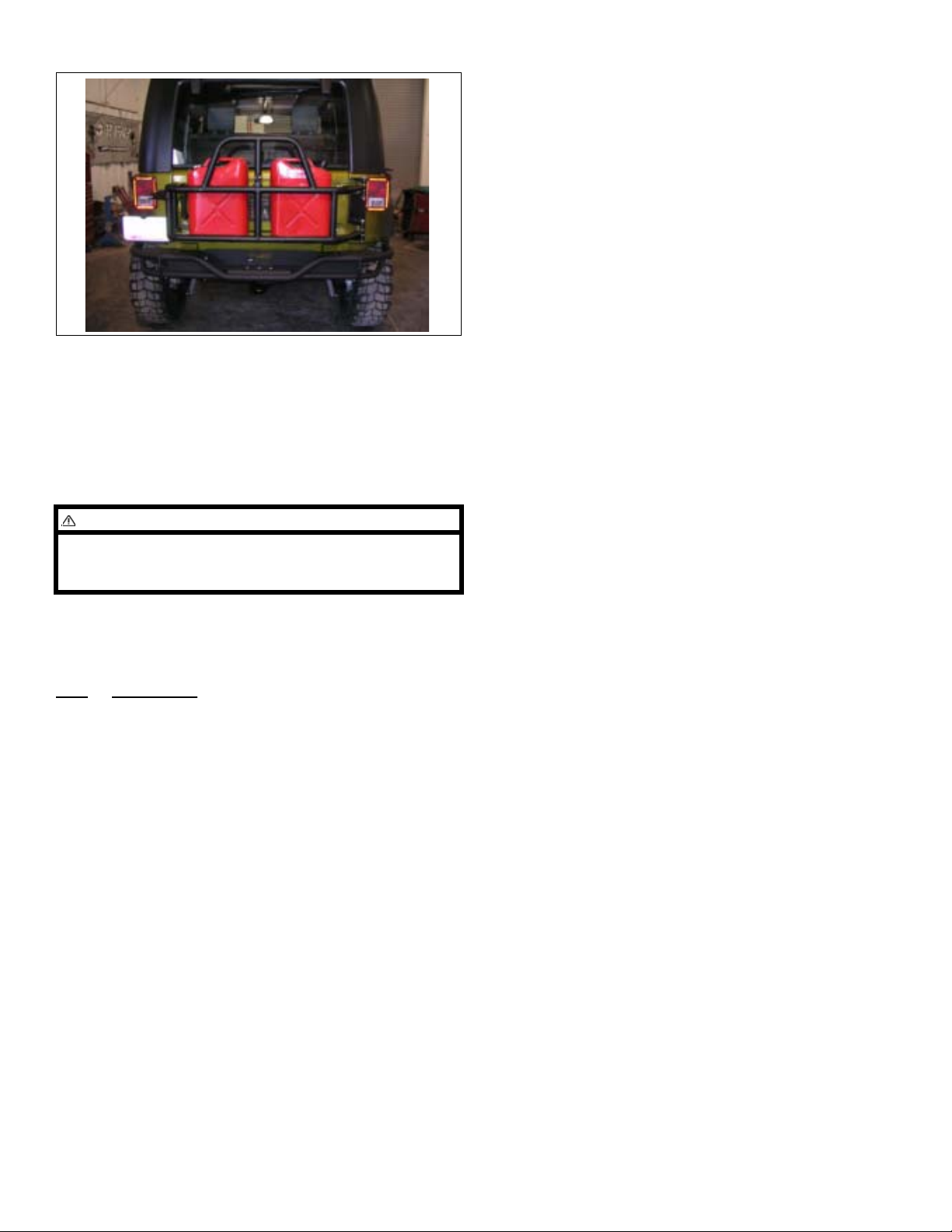
carrier itself. All pictures in these instructions reference the Tire/Can carrier model.
WARNING
Read and understand all instructions, warnings, cautions, and notes in this sheet and in your owners manual before you begin the installation of this tire/tire-can
carrier kit.
CAUTION
Proper installation of a ORFab tire carrier kit requires
knowledge of the factory recommended procedures for
disassembly and assembly of original equipment components. We recommend that the factory shop manual
and any special tools necessary to your vehicle be on
hand during the installation. Installation of this tire carrier lift kit without proper knowledge of the factory recommended procedures may affect the performance of
these components and the safety of your vehicle. We
strongly recommend that a certified mechanic familiar
with the installation of similar components install this
tire carrier kit.
WARNING
Some states require a center high-mount stop lamp by
law. OR Fab recommends that you consult your state
laws before you install this kit. If required you’ll need
optional (CHMSL) kit# 87017.
NOTE
Kit parts are prefaced by the word kit and appear in
bold print.
1. Carefully read all warnings and instructions completely before beginning.
2. Verify all parts have been received in this kit by
checking the parts list at the end of this document.
3. Only install this kit on the vehicle for which it is
specified. If anytime during the installation you
encounter something different from what is outlined
in the instructions, call technical support at (928)
636-7080.
4. Park the vehicle on a clean, dry, flat, level surface
and block the tires so the vehicle cannot roll in either
direction.
Tools needed:
1. Angle Drill
2. 1” hole saw OR Unibit 335
Swing-Away Tire/Can Carrier 1 Kit 85207 & 85208
Page 2
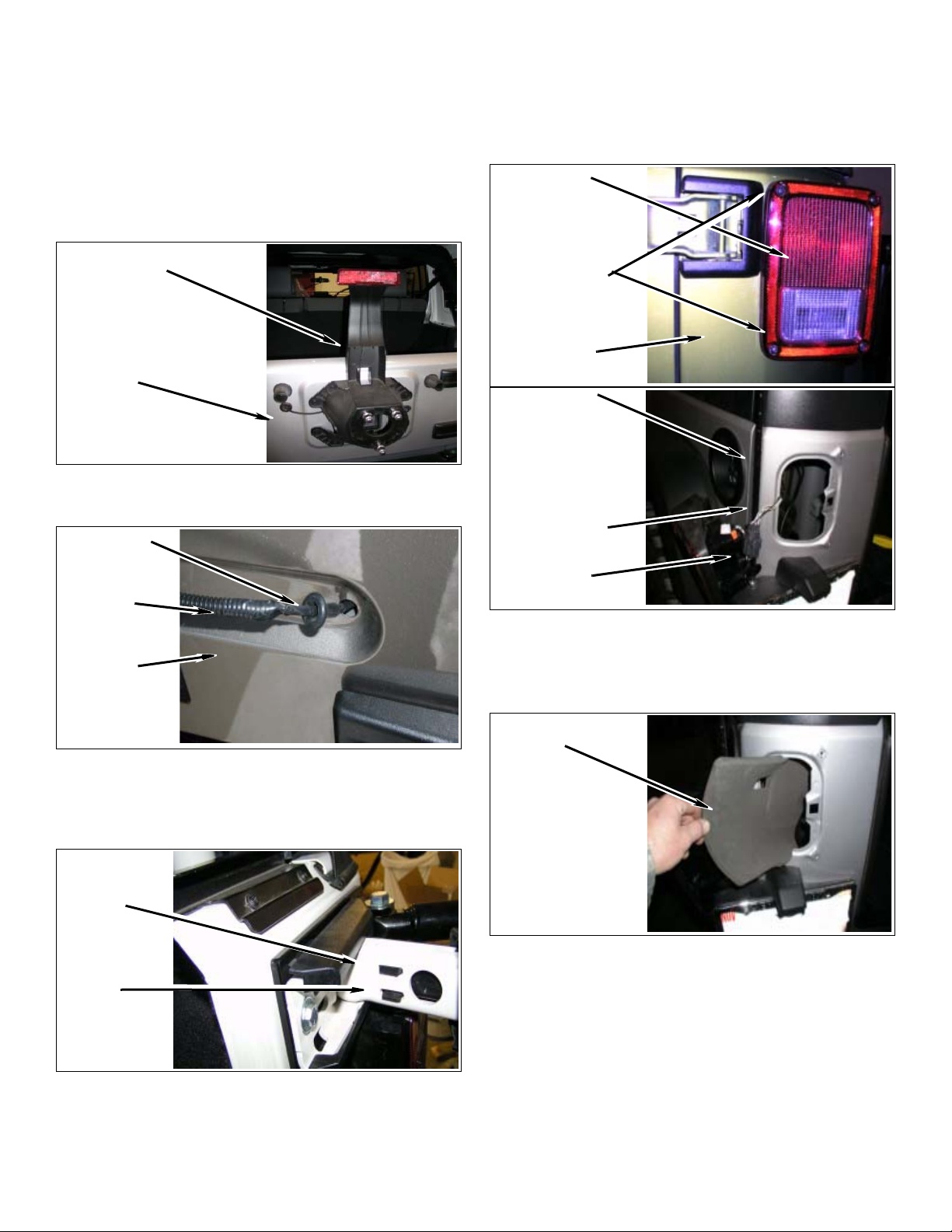
Prepare to install kit
3. Remove tail lights.
1. Remove spare tire.
2. Remove 3rd tail light and prep tailgate.
a. Remove factory spacer tire/third brake light
mount.
Remove factory
assembly
Tailgate
b. Remove grommet and wire harness from tail-
gate.
Grommet
a. Remove Tail lights from body. Only inner screws
toward the tailgate on each light need to be
removed.
Tail Light
Inner Screws
Jeep Body
Jeep Body
Light Opening
Wiring
Harness
Tailgate
c. Open tailgate. Unclip and remove both upper
and lower plastic covers from hinges at tailgate
and body. Make sure to mark upper and lower
for reinstallation.
Hinge
Clip
Harness
b. Unplug lights from Harness.
c. Remove Quarter panel inner foam liner both
sides and save for reinstallation.
Remove Foam
Liner
4. 2011-2012 Model: Remove two T30 torque bolts
and rear tail gate door guide from tail gate. Guide
Swing-Away Tire/Can Carrier 2 Kit 85207 & 85208
Page 3
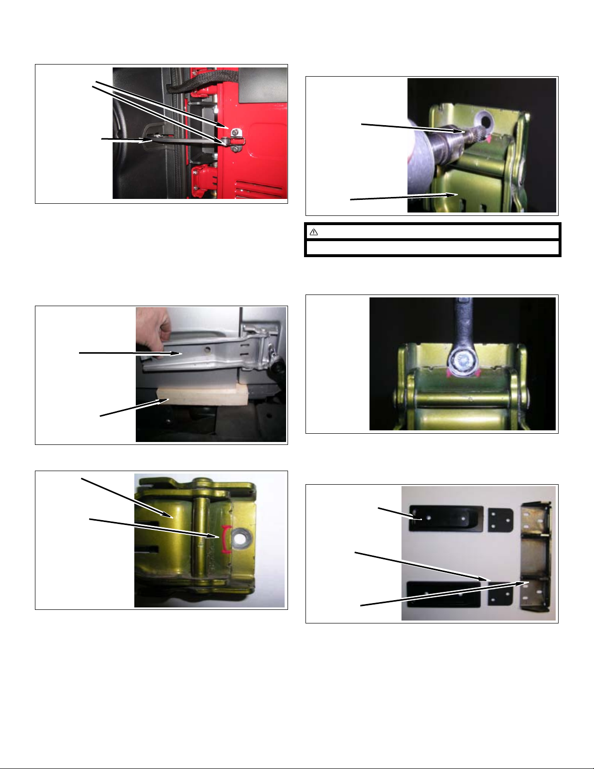
will no longer be able to to be used due to new tail
gate position when tail gate is fully opened. .
Remove Two
T30 Bolts
Door Guide
5. Remove tailgate hinge.
a. With tailgate closed in lock position, place 2x4
block of wood under bottom edge to support.
b. Remove both upper and lower tailgate hinges
with a T50 Torx bit.
a. Mark and grind out area shown on factory tail-
gate hinges to allow clearance for kit bolt (8mm
& tapered washer) and wrench during install.
Clearance
this area
Hinge
NOTE
Die grinder and rotary file work best for this task.
b. Hinge should open and close with clearance of
bolt head and 13mm wrench.
Tailgate
Hinge
Wood Black
6. Clearance hinges for wrench
Hinge
Clearance
this area
7. Install tailgate hinges, spacers, hinge plate spacers
and hinge plate to jeep body. Make sure rounded
edges of hinge spacer blocks are toward body.
kit Tailgate
Hinge Spacer
kit Hinge Plate
Spacer
kit Hinge Plate
Bracket
Swing-Away Tire/Can Carrier 3 Kit 85207 & 85208
Page 4
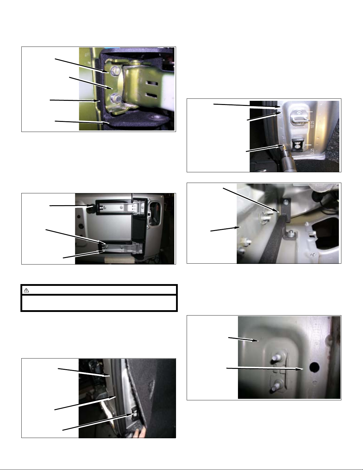
a. On inner two holes of hinge, Install using kit
bolts (8mm-1.25 x 50mm) with taper washers
(8mm). Do not tighten at this time.
kit bolts & taper
washer
OE tailgate hinge
(inner holes)
kit Hinge Plate
Spacer
kit Hinge Plate
Bracket
b. On outer hole of top hinge, Install using one kit
bolt (8mm-1.25 x 60mm) with taper washers
(8mm). Do not tighten at this time.
c. Install upper and lower tailgate spacers using
four kit bolts (8mm-1.25 x 50mm) with washers.
Do not tighten at this time.
kit Tailgate
Spacer
b. Find the center of the door chanel and measure
from inner lower corner of body up 3 7/8” for first
hole location and 10 7/8” for second hole
location center punch and drill 7/16” hole on
each as shown. (Note: Be sure to measure
against flat sheet metal surface and not on top of
body seam puddy. All JK’s may need some
minor adjustments made to these holes once
bracket is set in place; due to variances in body
panel positioning.)
Body
10 7/8” up, drill hole
3 7/8” up, drill hole
Landing
Block
Mount
OE T ailgate
Hinge
kit hardware
d. Align tailgate and snug bolts.
NOTE
Lower tailgate hinge spacer has deeper dish area in
face.
8. Install hing support bracket.
a. Open tailgate and remove carpet from area of
body around tailgate striker pad. Pull weather
stripping from door edge.
Edge of Tailgate
Opening
Body inner left
rear quarter
panel
c. Insert kit landing block mount bracket under
left rear of body and align holes in bracket to
holes drilled. Make sure bracket is snug to
inner body corner. Install kit bolts (5/16” x 3/4”)
and washers into bracket and snug but do not
tighten.
Inner Body
Near Striker
Drilled Hole
Weather
Stripping
Carpeting
Swing-Away Tire/Can Carrier 4 Kit 85207 & 85208
Page 5
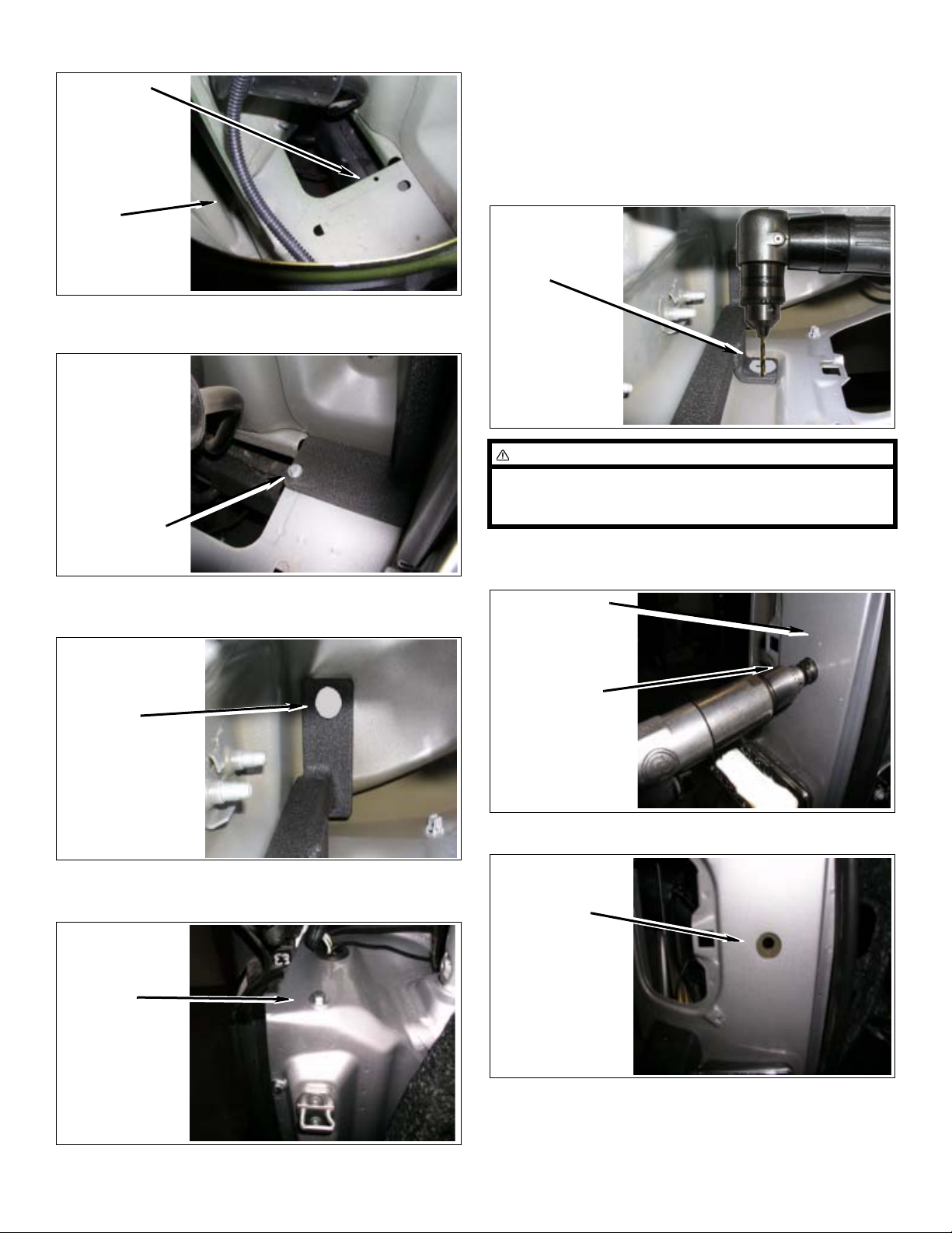
Use this
hole
Inner Left
Rear Quarter
Panel
d. Align foot of bracket to location shown here an d
install kit bolt (1/4” x 1”) with hardware.
kit landing
block mount
bracket
Install kit
bolt, 1/4” x 1”
g. Tighten all installed hardware in previous steps.
9. Drill and hole saw for landing block.
a. From under-inside of body center punch remain-
ing bracket hole on the rear inner body and drill
a 1/8” pilot hole.
drill 1/8”
hole
WARNING
Careful to keep drilling straight through as you will drill
two layers of body. An angle drill is highly recommended.
b. With hole drilled to outside of body as your pilot,
use 1” hole saw through only first layer of body.
e. From underside of body center punch and drill
upper hole into body with 1/8” pilot drill.
Pilot Drill
1/8” Hole
f. From top enlarge hole drilling with 3/8” drill and
install kit bolt (3/8” x 1”) and hardware.
kit bolt,
3/8” x 1”
Outer body
Drill open to 1”
c. Drill out remaining inner body layer to 1/2”
Drill to 1/2”
Swing-Away Tire/Can Carrier 5 Kit 85207 & 85208
Page 6
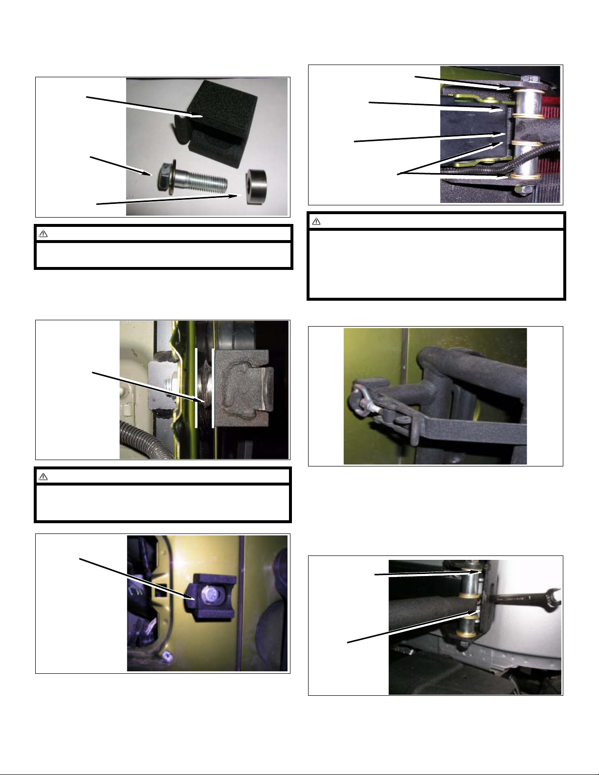
10. Install kit landing block to new hole in body support
bracket with kit bolt (1/2” x 2”), spacer (1/2” x1”),
and hardware. Snug but do not tighten.
kit landing
block
kit Bolt,
(1/2” x 2”)
kit Spacer
NOTE
Use RTV silicone sealer around spacer to make watertight seal to body.
11. NOTE: The gap between the body and the landing
block is required due to the contours of the body.
This gap will help the rack align properly.
wave washer “shim”, 1/2” sae washer, 1/2” lock nut,
1” spacer & 1.395” spacer)
kit Wave Washer
kit Spacer
kit Tire
Carrier
kit Brass Washer
NOTE
Place washers and spacers in order shown below. If
you have space or gap in the pivot washers use wave
washers or extra washers included for shimming. On
lower pivot spacers will be opposite position as top.
Use small amount of lithium grease on face of brass
washers to give better movement.
13. Adjust and tighten
Gap between
body & landing
block
WARNING
Careful to keep drilling straight through as you will drill
two layers of body. An angle drill is highly recommended.
kit landing
block
a. Close and latch rack.
b. Hinge plate has cut-out for 13mm box wrench to
tighten and for adjustments. Tighten both upper
and lower outside hinge plate bolts through cutouts.
kit Hinge
Plate
Slot
12. Install tire carrier rack to hinge plate with kit bolts (1/
2” x 5-1/2”) with hardware (1/2” brass washer, 1/2”
Swing-Away Tire/Can Carrier 6 Kit 85207 & 85208
Page 7
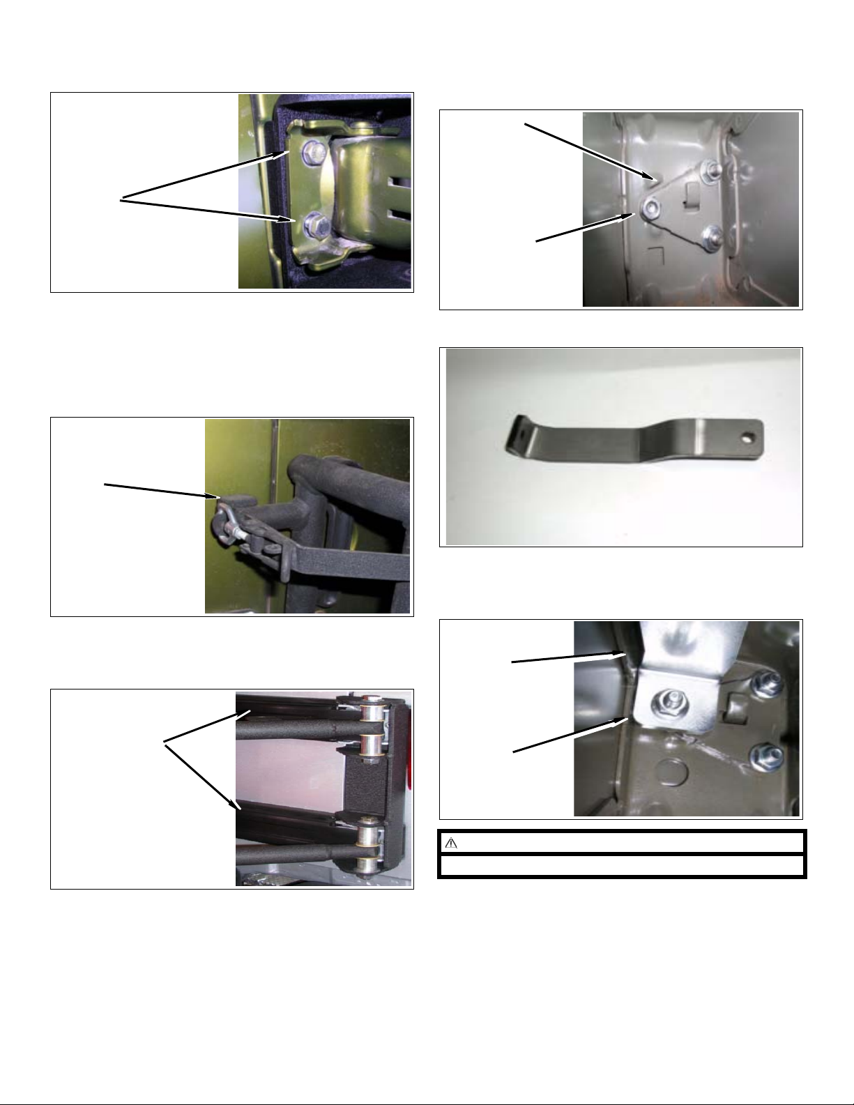
c. Now open carrier rack and tailgate to tighten
inner hinge plate bolts.
Tighten
d. Tighten Landing block position so hook area of
block just has enough clearance for landing bar
of rack, block is slotted for this adjustment.
Adjust rack latch hoop and tighten jam nut, this
will allow the latch to properly cam-lock itself
when in closed position.
f. Install on the back side of upper and lower hinge
plate using kit nut (8mm flange) and tighten
(exclude upper outer longer bolt for next step.)
kit Hinge
Plate
kit 8mm
flange nuts
14. Install kit hinge plate upper support bracket
Clearance
Area
e. Adjust tail gate for proper closing and tighten all
remaining bolts inside body. Reinstall tail gate
hinge plastic covers.
Plastic Covers
a. On underside of body top mount plate, place
bracket end on upper outer long hinge bolt
shown. Secure with kit nut (8mm flange)
kit hinge plate
upper support
bracket
kit nut (8mm
flange)
NOTE
Mechanics mirror will greatly help in this step.
b. On opposite end of bracket center punch and
pilot drill 1/8” hole up through the body.
Swing-Away Tire/Can Carrier 7 Kit 85207 & 85208
Page 8
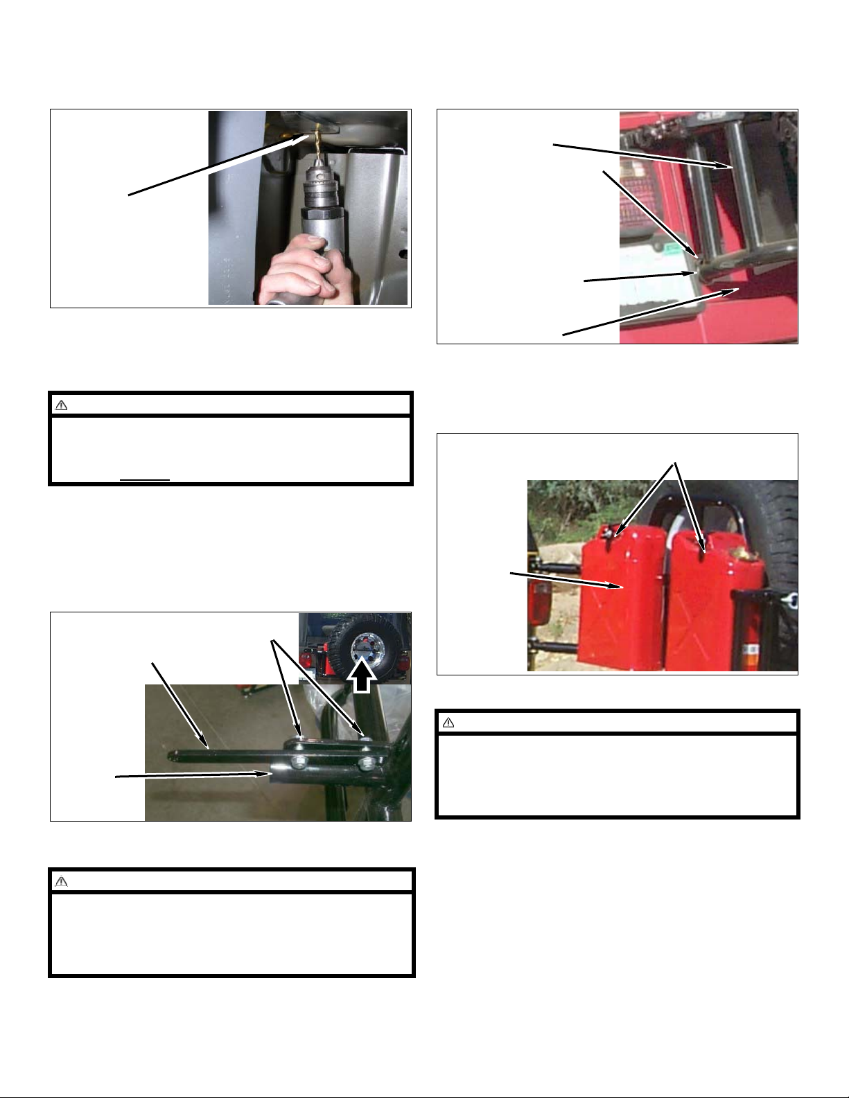
c. From top side inside of body enlarge hole to 3/8”
drill and install kit bolt (3/8” x 1”) with hardware
and tighten.
Drill to 3/8” and
install kit 3/8” x
1” bolt
b. Use the location of the kit lower bump-stop on
the tire carrier to position the kit 2” x 2” stain-
less steel stick pad on the tailgate.
Kit Tire Carrier
Kit Lower Bump-stop
Kit 2” x 2” Stainless
Steel Stick Pad
15. Reinstall quarter panel inner foam liner and tail lights
16. Tire mounting.
WARNING
The load rating for these tire-can/tire carriers is a
MAXIMUM of 200lbs. Please be aware that some tire
and wheel combinations along with gas cans and hi-lift
jacks can exceed
this MAXIMUM rating.
a. Install kit lock bar on kit tire carrier with two kit
bolts (5/16” x 1”) and two kit flange nuts (5/16”).
b. Position and install tire and wheel assembly on
kit tire carrier with kit urethane spacer, kit alu-
minum plate, and kit T-bar.
Kit Bolts 5/16” x 1”
Kit Flange Nuts 5/16”
Kit Lock Bar
Kit Tire
Carrier
Tailgate
c. Tire-can carrier only: Install your gas cans on
tire-can carrier using the bottom lip of the cans
along with two kit threaded rods (3/8 x 8”), kit L-
brackets and kit wing nuts as shown.
Kit Threaded Rods 3/8 x 8”,
Kit L-brackets, Kit Wing Nuts 3/8”
Gas Cans
NOTE
After installing tire and cans to rack, carrier may seem
to sag at latch end. Set pre-load to rack by adjusting
hinge plate landing bar to landing block is just abo ve
center of landing area. This will set pre-load after
weight is applied and will close properly.
17. Kit bump-stop.
CAUTION
In the step below you may need to slightly grind the
face of the kit lower bump-stop so that it will not dent
the tailgate. When adjusted properly the kit lower
bump-stop should just touch the tailgate and the kit 2”
x 2” stainless stick pad.
a. Install the kit lower bump-stop on the kit tire
carrier.
Swing-Away Tire/Can Carrier 8 Kit 85207 & 85208
Page 9
Accessories
The following accessories are also available:
Kit # 87013: Non-lip can carrier adapter.
Kit # 87269: Cargo box.
Kit # 87017:.Third brake light kit
1 Bolt, 1/4” x 3/4”
4 Washer, M8
1 Washer, 1/2” SAE (Hardened)
16 Washer, 1/2” Brass
2 Washer, M12
4 Washer, 1/2” SAE
2 Washer, 7/16” USS
2 Washer, 5/16” USS
3 Washer, 1/4” USS
6 Washer, M8 (90 degree)
1 Nut, 1/2” Flange
2 Nut, 1/2” Stover
2 Nut, 3/8” Flange
2 Nut, 5/16” Flange
1 Nut, 1/4” Flange
6 Nut, M8 Flange
2 Nut, 3/8” Wing
1 Spacer, Landing Block (.5 x 1.0)
2 Spacer, Pivot (1.395 x 1.0)
2 Spacer, Pivot (1.008 x 1.0)
1 End Cap, Urethane
1 Bumpstop
1 Self Adhesive 2” x 2” Pad
NOTE
Hi-lift jacks can be installed on the tire-can/tire carriers
with the use of two bolts (3/8” x 1 1/2”) not provided
with these kits.
Parts list
QTY Description
1 Rack, Carrier
1 Bracket, Hinge plate
1 Bracket, Landing block mount
1 Bracket, Support mount upper
1 Spacer, Tail gate hinge lower
1 Spacer, Tail gate hinge lower
2 Spacer, Hinge plate block
1 Landing block, Welded
1 T-Handle
1 Aluminum Disc
1 Spacer, urethane disc
1 Lock Bar
2 Can Clamp
2 Can Holder
1 Hardware Bag, (Tire Carrier)
1 Bolt, M8 x 60mm
9 Bolt, M8 x 50mm
2 Bolt, 1/2” x 5-1/2”
1 Bolt, 1/2” x 2”
2 Bolt, 3/8” x 1”
4 Bolt, 5/16” x 1”
Rev. 2 © 2008 OR-FAB
Performance Automotive Group, Inc.
Swing-Away Tire/Can Carrier 9 Kit 85207 & 85208
 Loading...