

Page 1
Before Starting Installation
NOTE
Kit parts are prefaced by the word kit and appear in
bold print.
3651 N Highway 89 • Chino Valley, AZ 86323
(928) 636-7080 • www.p-a-g.net
JEEP WRANGLER,
RUBICON, UNLIMITED (JK)
QUARTER ARMOR KIT
INSTALLATION INSTRUCTIONS
84330 07-12 JK 2Dr. W/LED
84331 07-12
JK 2Dr. “RAW” W/O LIGHT HOLES
84332 07-12 JK 2Dr . W/RAIL BAR & W/LED
84340 07-12 JK 4Dr. W/LED
84341 07-12
JK 4Dr. “RAW” W/O LIGHT HOLES
84342 07-12 JK 4Dr . W/RAIL BAR & W/LED
WARNING
Before you install this kit, read and understand all
instructions, warnings, cautions, and notes in this
instruction sheet and in the vehicle owner’s manual.
CAUTION
Proper installation of this kit requires knowledge of the
factory recommended procedures for removal and
installation of original equipment components. We recommend that the factory shop manual and any special
tools needed to service your vehicle be on hand during
the installation. Installation of this kit without proper
knowledge of the factory recommended procedures
may affect the performance of these components and
the safety of the vehicle. We strongly recommend that
a certified mechanic familiar with the installation of similar components install this kit.
1. Carefully read all warnings and instructions completely before beginning.
2. Verify all parts have been received in this kit by
checking the parts list at the end of this document.
NOTE
If parts are missing from kit, please be prepared to provide the following information:
1. Name of purchase location
2. Bar Code on side of box
3. Date above bar code
4. Date inside box cover
5. Inspector # from inside box cover
3. Only install this kit on the vehicle for which it is
specified. If anytime during the installation you
encounter something different from what is outlined
in the instructions, call technical support at (928)
636-7080.
4. Special tools needed:
a. Drill with 1/4” - 3/8” - 9/16” drill bits
b. Center punch
c. Allen Tool Set
d. C-clamp Vice Grip “wid e Jaw”
e. Electrical Crimp Tool
f. Test Light
Recommend purchasing
and installing this
kit
2dr Rocker Armor (84310)
kit
prior to quarter armor install. This
will insure proper alignment and fitment of quarter armor.
**Use a light amount of oil on kit button head bolts when
installing bolts into rivet to help prevent thread damage**
WARNING
Always wear eye protection when operating power
tools.
WARNING
Before you install this kit, block the vehicle tires to prevent the vehicle from rolling.
5. Park vehicle on a clean, dry, flat, level surface and
block tires so vehicle cannot roll in either direction.
Engine Compartment
1. Disconnect both battery cables. Disconnect nega-
tive cable first, then positive cable.
1 JEEP JK Quarter Armor Kit
Page 2
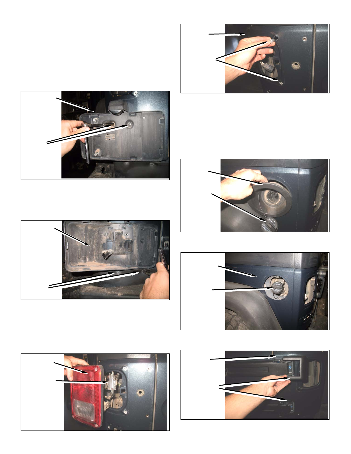
Remove Rear Trim
c. Remove screw clips from vehicle panel.
1. Remove rear license plate frame from vehicle.
a. Using a wrench or screw driver remove licence
plate.
b. Using an 8mm socket; remove two screws from
inside liner, followed by removing the inside liner
holding the licence plate light and harness.
License Plate
Frame
Remove
Remove
Screws
Screws
c. Disconnect license plate harness.
d. Using an 8mm socket, remove two screws from
lower licence plate frame and remove licence
plate frame from rear quarter panel.
Dvr. Side
Panel
Remove
Screw Clips
d. Remove gas cap from filler neck.
e. Gently pry gas filler housing away from sheet
metal quarter without distorting sheet metal
around gas filler housing.
Note: Don’t worry if you brake a clip while removing gas
filler housing; they can be removed in a later step of
these instructions.
Gas Filler
Housing
Gas Cap
License Plate
Frame
Remove
Screws
2. Remove rear tail lights from vehicle.
a. Using a screw driver; remove two inner scre ws
from each tail light housing.
b. Disconnect tail light harness and remove tail
lights from rear quarter panel.
Tail Light
Disconnect
Harness
f. Reinstall gas cap to prevent any particles from
entering the filler tube.
Rear Quarter
Panel
Gas Cap
g. Remove passenger rear hinge trim cover from
hinge mounts.
Psg. Side
Panel
Remove
Hinge Covers
2 JEEP JK Quarter Armor Kit
Page 3
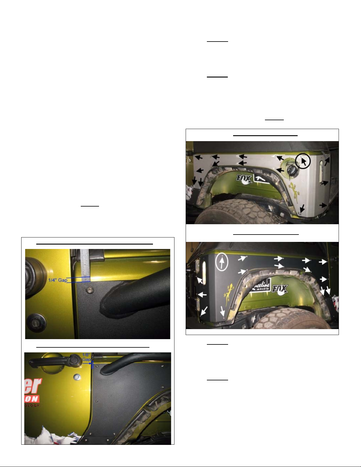
Prepare to Install Kit
c. Once kit armor is properly placed and aligned,
mark all appropriate holes for drilling
1. Prepare mounting points.
a. Using an assistant, hold kit armor in place and
use C-clamps around the outside of the panel to
hold kit armor into place. (Note: Aligning the rear
upper edge of kit armor an 1/8” below body line
radius and centered with gas door hole. The bottom edge of kit armor should line up square with
the radius of the lower edge. The front of th e kit
armor should be aligned so that it provides
proper clearance for door operation. See notes
below)
b. When aligning kit armor to door line edge; be
sure to square kit armor up to the exact lines of
the door line. Make sure you have a 1/8” gap
between the kit armor and the door line. The top
edge of the kit armor should have a 1/4” gap
between the kit armor and the top body line
near the front edge of the door.
Note: Be sure to align 2dr. kit armor correctly you must
follow this procedure due to the slight cone/offset shape
in the body lines. It is highly
2dr. rocker panel armor (84310) prior to installing kit
2dr. quarter armor to insure proper alignment and
fitment of armor. These steps will help prevent mounting
the kit armor to high on the body of the Jeep.
2 Dr. Front Upper Section Measurement
recommended to install kit
d. 2 Door
holes drilled to 3/8” & 1 - tail light hole drilled to
9/16” for clearancing kit LED Light bolt & nut
assembly.
e. 2 Door
holes drilled to 3/8” & 1 - tail light hole drilled to
9/16” for clearancing kit LED Light bolt & nut
assembly.
NOTE: Kit 2 door armor w/rail bar will only require 14 holes drilled to 3/8” due to kit rail bar
circled below will not be marked or drilled during install.
: Dvr. side kit armor will require 15 -
: Psg. side kit armor will require 15 -
location. The arrow
Dvr Side 2 Door Panel
Psg. Side 2 Door Panel
2 Dr. Front Door Section Measurement
f. 4 Door: Dvr. side kit armor will require 12 -
holes drilled to 3/8” & 1 - tail light hole drilled to
9/16” for clearancing kit LED Light bolt & nut
assembly.
g. 4 Door
holes drilled to 3/8” & 1 - tail light hole drilled to
9/16” for clearencing kit LED Light bolt & nut
assembly.
NOTE: Kit 4 door armor w/rail bar will only require 11 -
holes on Dvr. side & 10 - holes on Psg. side drilled to
3/8” due to rail bar location.The arrow circled below will
not be marked or drilled during install.
3 JEEP JK Quarter Armor Kit
: Psg. side kit armor will require 11 -
Page 4
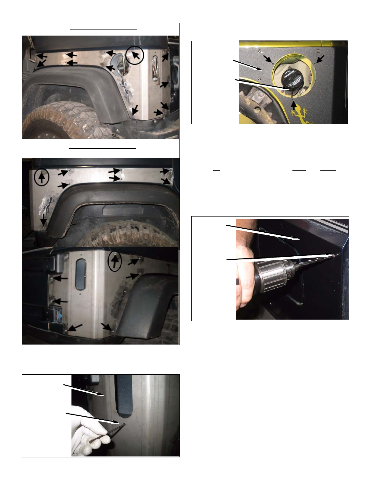
Dvr Side 4 Door Panel
Psg Side 4 Door Panel
i. Mark three holes surroung ing the gas filler hole
for drilling out to 1/4” once you have removed kit
armor panels.
Dvr. Side Kit
Armor Panel
Mark Three
Gas Filler
Holes for
Drilling
j. Once all kit armor is marked correctly for drill-
ing; remove kit armor and prepare to drill all
mounting holes.
k. Drill all marked holes using a 3/8” in only the
15
rear holes marked in the 2-Dr. and 10-11 rear
holes marked in the 4-Dr.
the figure below. DO NOT drill deeper than 1”
anywhere in the body.
(per side) as shown in
h. Mark both lower LED mounting holes for drilling
out to 9/16” once you have removed kit armor
panels.
Psg. Side Kit
Armor Panel
Mark Lower
LED Mounting
Hole for Drilling
NOTE: Some hole will need to be drilled through two
layers for the rivel to slide in flush with the body.
Dvr. Side
Panel
Drill 3/8”
Mounting
Hole for Kit
Rivet
l. Install rivet nuts into the 3/8” holes as follows:
Completely retract the slide and install rivet nut
finger tight on the stud. Place the stabilizing rod
in the provided hole. Insert rivet nut into the
drilled hole and tighten the slide screw to draw
the slide up the ramp. A light coating of grease
on the ramp and a drop of oil on the tightening
screw will ease the operation of the tool. Typically , you will need to loosen the slide screw and
screw the 1/4”-20 bolt finger tight again repeat at
least twice until the rivet nut it tight and won’t
spin. This will set the rivet nut.
4 JEEP JK Quarter Armor Kit
Page 5
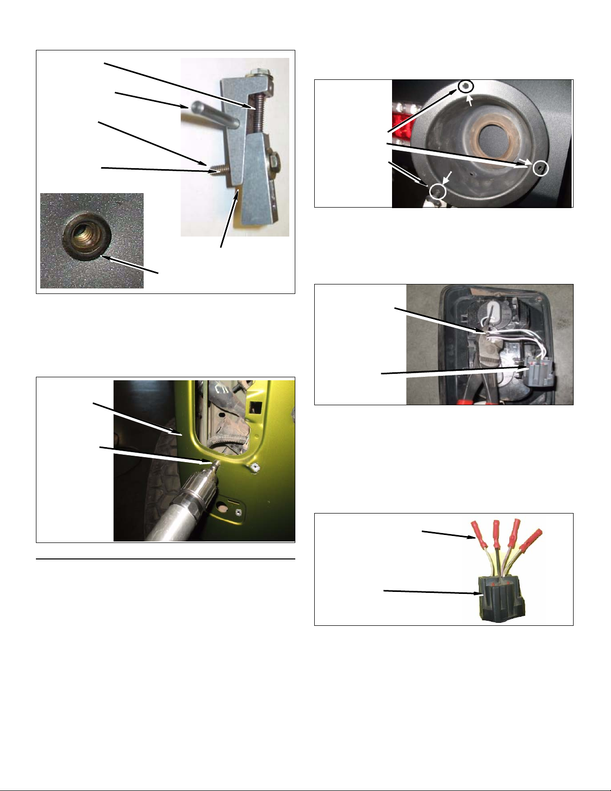
NOTE: Be sure not to over tighten the rivet, doing so will
prevent damage to the rivet’s threads.
Slide Screw
Stabilizing Rod
Rivet Nut
Goes Here
1/4”-20 Bolt
b. Using pin on gas filler housing as an alignment
tool; center housing onto Dvr. side kit armor.
Mark and drill three 1/4” holes into gas filler
housing.
Drill Three 1/4”
Holes into Gas
Filler Housing
3. Wire Kit LED Tail Light Plugs (Harness).
Rivet Nut Tool
Rivet Nut Installed
m. Once you have finished installing all of the kit
rivets; be sure to clean / tap each rivet threads
to prevent cross threading from occuring.
n. Drill a 9/16” hole through both lower LED mount-
ing hole markes for bolt & nut clearence.
Dvr. Side
Panel
Drill 9/16”
Lower LED
Mounting Hole
for Clearence
a. Locate OEM tail light and remove plug from tail
light housing using a pair of wire cutters.
NOTE: Leave a few inches of wires at the end of the plug.
Cut Plug Harness
Leaving a Few
Inches of Wire at
the End of Plug
OEM Tail
Light Plug
b. Using OEM tail light plug, take a pair of wire
stripers and remove a small amount of insulation
to expose the tip of all four wires at the end of
the OEM plug for each kit butt connector.
c. Using four kit butt connectors; take a pair of
crimpers and crimp one kit butt connector to
the end of each OEM plug wire.
Kit Butt Connector
*STEP 2 need only be performed if clips are damaged
2. Drilling gas filler housing.
a. Using a pair of pliers, gently remove all four clips
surrounding gas filler housing.
OEM Tail
Light Plug
d. Inst all two kit plug harnesses into each insert on
the back of kit LED light.
e. Prep both kit plug harness to be connected to
OEM plug with kit butt connectors.
5 JEEP JK Quarter Armor Kit
Page 6
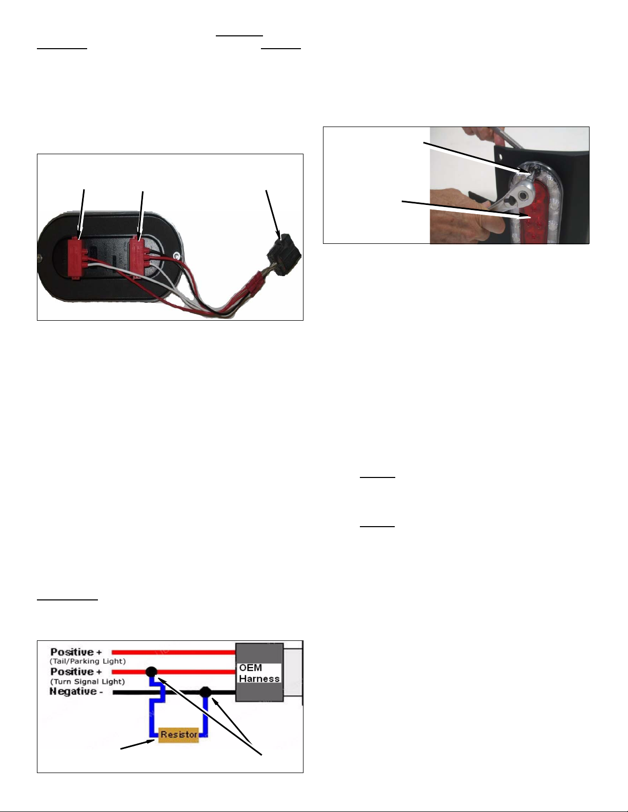
NOTE: Kit “Top Plug” will not use the black wire
OEM Plug
--- Kit Plug
on plug.
Install Kit Armor
(Ground) Black --- (Top/Bottom) White
(Backup) White/Green --- (Top) Red
(Tail) White/Purple --- (Bottom) Black
(Stop&Turn) White/Yellow --- (Bottom) Red
Kit Plugs connected to OEM Plug
Top
**Repeat processes to each tail light harness**
4. Install kit LED load resistor
a. Find the correct turn signal / stop wire in the tail
light harness; on the Jeep OEM side. The wire
color should be White / Yellow stripe. Connect
one end of kit resistor to wire using a kit mid-
line wire tap. Connect the other end of kit resis-
tor to the black ground wire in the same harness
using another kit mid-line wire tap. (Note:
Repeat process to each tail light harness.)
b. Once you have connected your kit resistor in-
line to your OEM light harness; mount your kit
resistor mounting plate using kit 1/4” hard-
ware into inside sheet metal by drilling 1/4” hole
and mounting kit resistor plate to sheet metal
with kit 1/4” bolt, nut & washers.
*WARNING*
LED load resistors mounting plate / resistor. Mount
resistor away from any fuel lines, plastics, wires or carpet
to prevent any minor / major damage to vehicle.
Bottom
Use extreme caution when installing kit
OEM Tail
Light Plug
1. Install Kit LED Tail Lights onto Kit Armor.
a. Install kit LED light onto kit armor using two kit
socket cap screws, washers, and nylon nuts
through kit armor to fasten light onto armor.
Install Kit Hardware
Kit LED Light
Be sure to install kit plug harnesses onto kit LED light
prior to installing kit armor.
2. Install Kit Rear Armor.
a. Using an assistant, hold kit armor in place and
use C-clamps around the outside of the panel to
hold it into place. (NOTE: Aligning the upper
edge of kit armor with body line. The bottom
edge of kit armor should line up with the radius
of the lower edge. The front of the kit armor
should be aligned so that it provides proper
clearance for door operation.)
b. Once kit armor is properly placed and aligned,
start installing kit 1/4” hardware and plug kit
LED plug harness into OEM tail light harness.
c. 2 Door
button head bolts (1/4-20x3/4”) for bolting up
kit rear armor.
d. 2 Door
button head bolts (1/4-20x3/4”), 1 - flange nut
(1/4-20”) & flat washer (Large) for bolting up kit
rear armor. (Note: One kit bolt, nut & washer
will be installed throught top left corner of kit
armor, near the top tail gate hing mount, and
mount through the small top tail light mounting
hole.)
NOTE: Kit 2 door armor w/rail bar will only require 14 bolts, nuts & washers installed due to kit rail bar loca-
: Dvr. side kit armor will require 1 5 - kit
: Psg. side kit armor will require 15 - kit
Kit LED Load Resistor
Kit Mid-Line Wire Tap
6 JEEP JK Quarter Armor Kit
Page 7
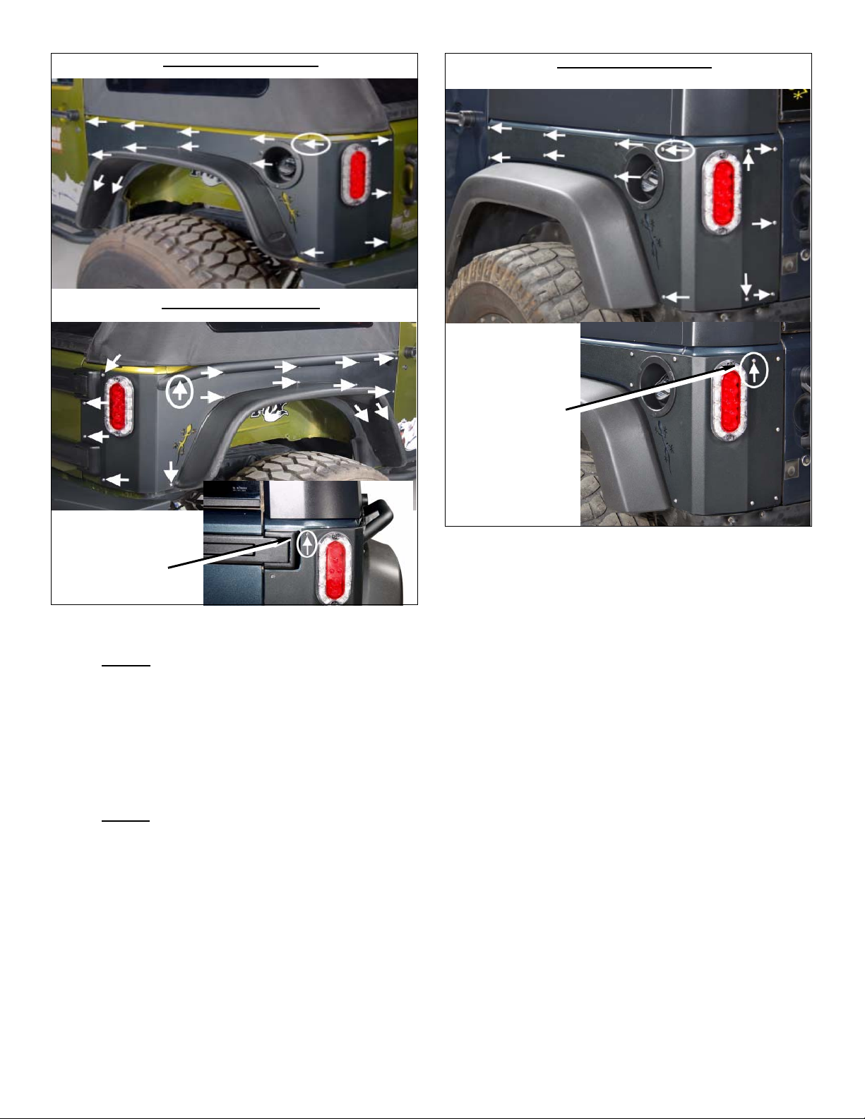
tion. The arrow circled below will not require hardware.
Dvr Side 2 Door Panel
Psg. Side 2 Door Panel
circled below will not require hardware.
Dvr Side 4 Door Panel
Drv. Side 4 Door
Kit Bolt, Nut &
Washer Installed
Psg. Side 2 Door
Kit Bolt, Nut &
Washer Installed
**Align and tighten all the kit button head bolts**
e. 4 Door: Dvr. side kit armor will require 13 - kit
button head bolts (1/4-20x3/4”), 1 - flange nut
(1/4-20”) & flat washer (Large) for bolting up kit
rear armor. (Note: One kit bolt, nut & washer
will be installed throught top center right corner
of kit armor, near the top tail light mount, and
mount through the small top tail light mounting
hole.)
f. 4 Door
button head bolts (1/4-20x3/4”), 1 - flange nut
(1/4-20”) & flat washer (Large) for bolting up kit
rear armor. (Note: One kit bolt, nut & washer
will be installed throught top left corner of kit
armor, near the top tail gate hing mount, and
mount through the small top tail light mounting
hole.)
: Psg. side kit armor will require 12 - kit
**Align and tighten all the kit button head bolts**
**Using a light amount of oil on kit button head bolts
when installing into rivet to prevent cross-threading**
--Access hole at bottom of rear quarter panel may be
used for access to rear tail light harness and bolts by
removing the inside foam liners--
NOTE: Kit 4 door armor w/rail bar will only require 12 on Dvr. side & 11 - holes on Psg. side; bolts, nuts &
washers installed due to kit rail bar location. The arrow
7 JEEP JK Quarter Armor Kit
Page 8
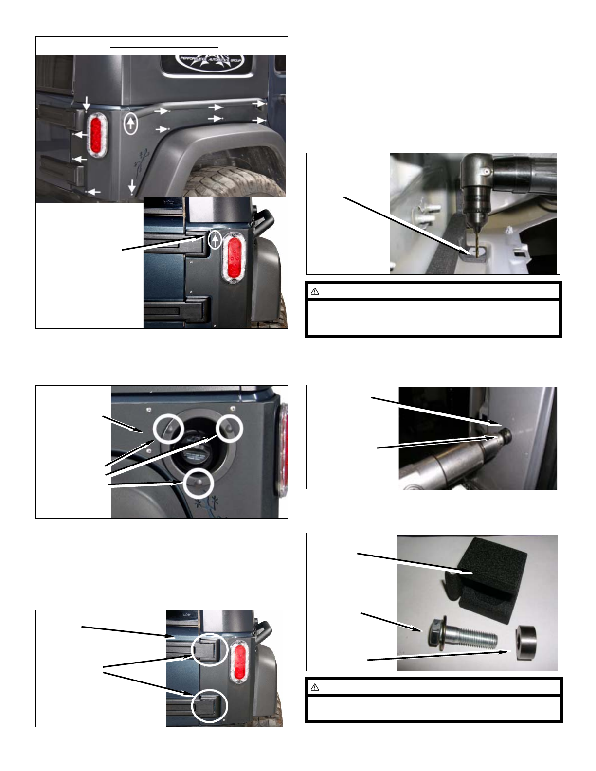
Psg Side 4 Door Panel
Psg. Side 4 Door
Kit Bolt, Nut &
Washer Installed
3. Install gas filler housing.
a. Using three kit push clips (1/4”) through gas
filler housing and into armor.
b. Align and tighten all the kit button head bolts.
ORF Tire Carrier Modifications
1. Installing landing block over driver side armor.
a. From under-inside of body center punch remain-
ing bracket hole on the rear inner body and drill
a 1/8” pilot hole.
drill 1/8”
hole
WARNING
Careful to keep drilling straight through as you will drill
two layers of body. An angle drill is highly recommended.
b. With your pilot hole drilled through outside of
body & armor, use 1” hole saw through kit armor
and only first layer of body.
Dvr. Side Kit
Armor Panel
Install Gas
Filler housing
using Three
Kit
Push Clips
b. Reinstall gas cap once filler housing is seated
into place onto kit armor.
4. Install Hinge Caps.
a. Reinstall rear tail gate hinge caps on passenger
side hinges.
Tail Gate
Reinstall
Hinge Covers
Outer body &
Kit Armor
Drill open to 1”
2. Install kit landing block to new hole in body support
bracket with kit bolt (1/2” x 2”), spacer (1/2” x1”),
and hardware. Snug but do not tighten.
kit landing
block
kit Bolt,
(1/2” x 2”)
kit Spacer
NOTE
Use RTV silicone sealer around spacer to make watertight seal to body.
8 JEEP JK Quarter Armor Kit
Page 9
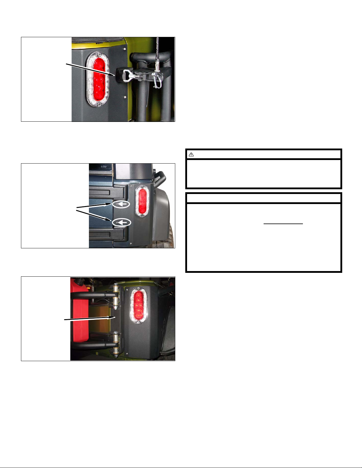
NOTE: The minor gap between the kit armor and the
landing block is required due to the contours of the body.
This gap will help the rack align properly.
b. OR-Fab offers two options for relocation your
license plate with kits: 87035 for you T-Handle or
87037 for your OEM tail gate. Also recommend
using ORO LitePLATE for a license plate light.
Gap between
armor & landing
block
3. Installing hinge bracket over passenger side armor.
a. Remove two kit button head bolts (1/4 - 20 x
3/4”) from kit armor, between both hinge
mounts.
Remove two kit
button head bolts
b. Place carrier hinge mount over the top of kit
armor, pinching the kit armor in between both
the body and the carrier mount.
Engine Compartment
1. Connect both battery cables. Connect positive cable
first, then negative cable.
Miscellaneous
1. Check all fasteners to ensure they are tight.
2. Ensure all wires, hoses, cables, etc. are properly
connected and there is ample slack.
WARNING
Retorque all fasteners after 500 miles and after off road
use. All armor components should be visually
inspected and fasteners retorqued during routine
vehicle servicing.
NOTE
All warranty information, instruction sheets, and other
documents regarding the installation of this product
must be retained by the vehicle owner
contained in the instructions and on the warranty card
will be required for any warranty claims. The vehicle
owner needs to understand the modifications ma de to
the vehicle and how they affect vehicle handling and
performance. Failure to provide the customer with this
information can result in damage to the vehicle and
severe personal injury.
. Information
Mount Carrier
Hinge Bracket
Over Kit Armor
After Completing Installation
Finish Installation
1. Relocate license plate
a. Find a good visible area on the back of your
vehicle to relocate you license plate and light.
Accessories
The following accessories are also available:
Kit 87035: T-Handle License Plate Relocation
Kit 87037: Tail Gate License Plate Relocation
Kit 87036: Tail Gate Vent Plate
Kit 85209: Rotopax Tire Carrier
Kit 87321: 2Dr. Quarter Armor Liner
Kit 87322: 4Dr. Quarter Armor Liner
Kit 84310: 2Dr. Rocker Armor
Kit 84320: 4Dr. Rocker Armor
9 JEEP JK Quarter Armor Kit
Page 10
Kit Parts List
Qty. Description
1 Quarter Panel Armor (Drivers side)
1 Quarter Panel Armor (Passenger side)
2 LED Light
4 LED Plug (Wire Harness)
2 DOOR HARDWARE BAG
32 Bolt (1/4” x 3/4”)
1 Nut, Flange (1/4”)
31 Rivet Nut (1/4”)
1 Washer, Fender (5/16”)
3 Ratchet Fastener (1/4”)
4 Socket Cap Screw (#10)
4 Nylon Jam Nut (#10)
4Washer (#10)
8 Butt Connector
4 DOOR HARDWARE BAG
26 Bolt (1/4” x 3/4”)
1 Nut, Flange (1/4”)
24 Rivet Nut (1/4”)
1 Washer, Fender (5/16”)
3 Ratchet Fastener (1/4”)
4 Socket Cap Screw (#10)
4 Nylon Jam Nut (#10)
4Washer (#10)
8 Butt Connector
Rivet Nut Tool Bag
2 Washer, Hardened (1/4”)
1 Bolt, Grade 8 (1/4” x 1-1/2”)
1 Bolt, Grade 8 (1/4” x 1-3/4”)
1Stabilizer Pin
1 Base Ramp
1Slide
Resistor Kit Bag
2 LED Resistor (Resistor w/ Mounting Plate)
2Bolt (1/4”)
2 Nut, Lock (1/4”)
4Washer (1/4”)
4Tap (Mid-Line Wire Tap)
NOTE
Depending on the vehicle and kit configuration
(2 Door or 4 Door), some parts may not be used.
10 JEEP JK Quarter Armor Kit
 Loading...