

Page 1
Before Starting Installation
NOTE
Kit parts are prefaced by the word kit and appear in
bold print.
3651 N Highway 89 • Chino Valley, AZ 86323
(928) 636-7080 • www.p-a-g.net
JEEP CHEROKEE 2 & 4 DOOR
REAR “COMP CUT” BUMPER
INSTALLATION INSTRUCTIONS
1984-2001 KIT# 83245
WARNING
Before you install this kit, read and understand all
instructions, warnings, cautions, and notes in this
instruction sheet and in the vehicle owner’s manual.
CAUTION
Proper installation of this kit requires knowledge of the
factory recommended procedures for removal and
installation of original equipment components. We recommend that the factory shop manual and any special
tools needed to service your vehicle be on hand during
the installation. Installation of this kit without proper
knowledge of the factory recommended procedures
may affect the performance of these components and
the safety of the vehicle. We strongly recommend that
a certified mechanic familiar with the installation of similar components install this kit.
WARNING
1. Carefully read all warnings and instructions com-
pletely before beginning.
2. Verify all parts have been received in this kit by
checking the parts list at the end of this document.
NOTE
If parts are missing from kit, please be prepared to provide the following information:
1. Name of purchase location
2. Bar Code on side of box
3. Date above bar code
4. Date inside box cover
5. Inspector # from inside box cover
3. Only install this kit on the vehicle for which it is
specified. If anytime during the installation you
encounter something different from what is outlined
in the instructions, call technical support at (928)
636-7080.
4. Park vehicle on a clean, dry, flat, level surface and
block tires so vehicle cannot roll in either direction.
Engine Compartment
Many states and municipalities have laws restricting
bumper heights and vehicle lifts. Consult state and
local laws to determine if the changes you intend to
make to the vehicle comply with the law.
WARNING
Always wear eye protection when operating power
tools.
WARNING
Before you install this kit, block the vehicle tires to prevent the vehicle from rolling.
NOTE
Performance Automotive Group recommends using
the Loctite® supplied in the kit on the threads of all kit
nuts and bolts unless specified otherwise in these
instructions.
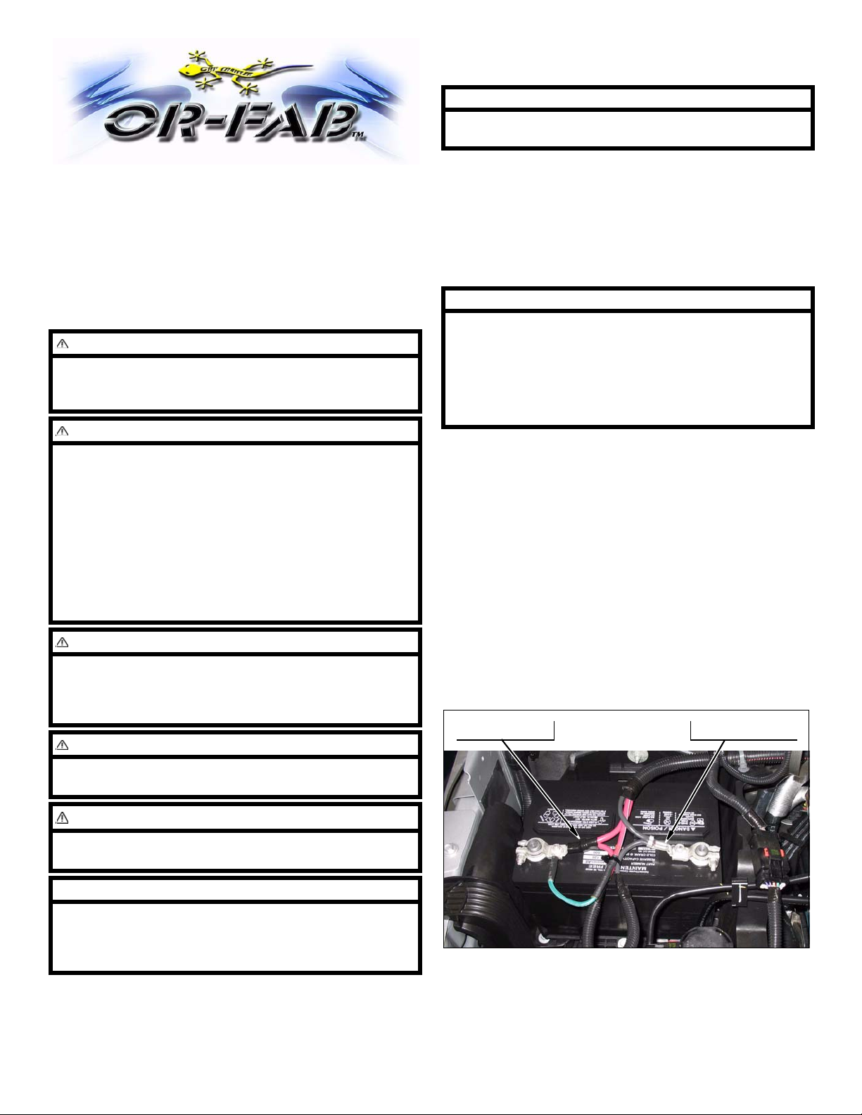
1. Disconnect both battery cables. Disconnect negative
cable first, then positive cable.
Positive Cable Negative Cable
1 XJ HD Rear “COMP CUT” Bumper - Kit 83245
Page 2
Rear Bumper
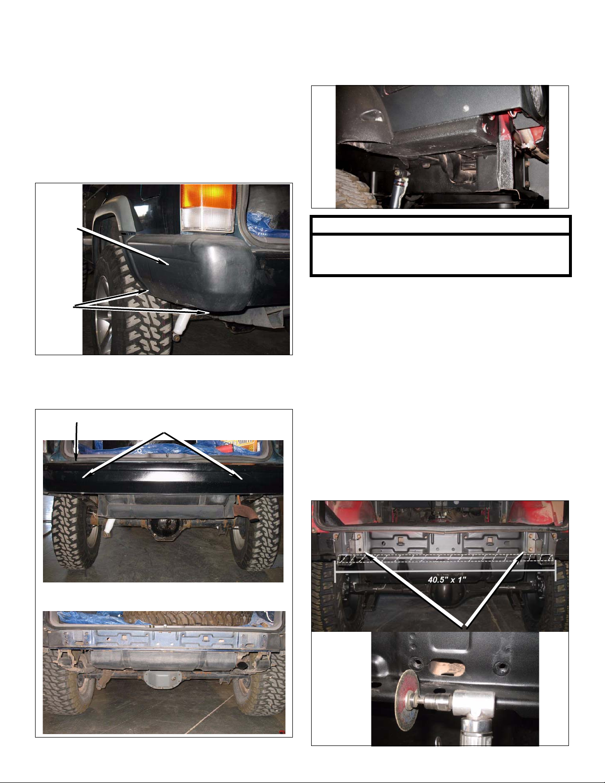
1. Remove Factory Bumper
a. 97-Up: Remove two bolts from corner section
on bottom side of bumper. Then gently push up
and remove corner section.
b. Af ter corner section is removed you may remove
existing bracket by drilling out the rivets(1/4” drill
bit) and remove bracket from rear quarter panel.
“Comp Cut” Rear Quarter Panels
1. Rear Quarter Panels Cut & Folded
Corner
section
Bolts
c. 84-01: Remove eight bolts from center section
bumper brackets (right & left) at frame and
remove bumper.
Rear bumper
Remove eight bolts at
Frame
**NOTE**
**Please view pages 5 - 8 for detailed
instructions on “Cutting and Folding”
Cherokee rear quarter panels.**
Prepare to Install Kit
Rear Bumper Install
1. Mark, Cut & Remove rear sheet metal sections
a. Using the two kit mounting brackets, place them
in the factory mounting position and mark the
outside lip of the sheet metal section that will
need to be removed so the two kit bumper
brackets will be allowed to sit flush against the
factory mounting surface.
NOTE: “Mark and Cut” a 40.5”x1” section out of rear lip
Rear mounts after bumper is removed
Rear kit Bumper Brackets
2 XJ HD Rear “COMP CUT” Bumper - Kit 83245
Page 3
2. Install Rear Bumper Bracket and Anchore Strap.
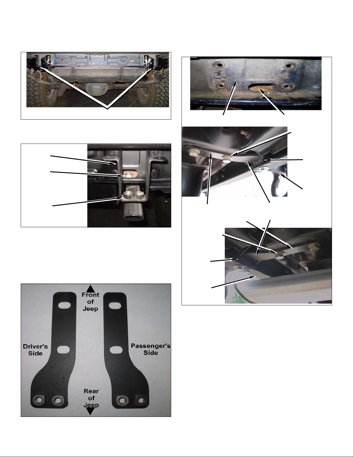
a. Install eight factory bolts into supplied kit
brackets and frame mounts.
d. DO NOT TIGHTEN at this time. (Note: Each
vehicle may very due to added accessories. 91’
& older models will requier you to mark &
drill 1/2” holes to tie in the anchore straps to
the frame). Repeat to passanger side.
Rear bumper brackets
b. Place two kit spacers (1/2”) on to kit bumper
mounting bracket.
Bumper
Bracket
Nut Plate
Spacers
c. Install kit nut plate(Two 1/2” nuts weld on a
plate) into frame rail through access hole in
frame. Using supplied kit hardware, two 1/2”
bolts & washers, to install anchore strap on
driver’s & passenger’s side frame mounts.
(Note: 7/16” nuts facing up.)
Mounting Flange
Anchore Strap mounts to
factory frame rail mount
1/2” Hardware
Spacers
Install nut plate through frame rail
1/2” Hardware
Spacers
Bumper
Anchore Strap mounted
to bumper bracket
Bumper
Rear Bumper Assembly
1. Install kit bumper on vehicle.
a. Place rear bumper up to mounts, align mounting
holes and use four kit (7/16 x 1 1/4” bolt,
washer, & flange nut) mounting hardware to
secure top of kit bumper to kit mounting
brackets.
3 XJ HD Rear “COMP CUT” Bumper - Kit 83245
Page 4
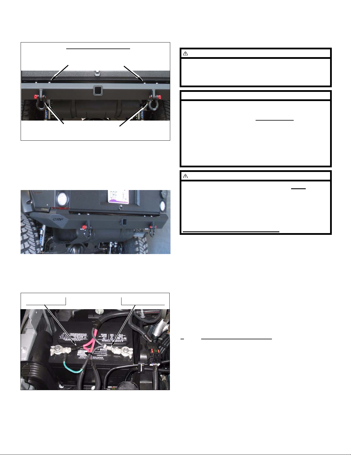
b. Use four kit (7/16 x 2” bolt, washer, & flange
nut) mounting hardware to secure bottom of
bumper to kit anchor and mounting brackets.
Rear Bumper Installed
Install Four (7/16 x 1 1/4”)
mounting hardware
Install Four (7/16 x 2”)
mounting hardware
2. Align and Center bumper assembly(Be sure that
rear hatch clears bumper), tighten all six mounting
bolts.
Miscellaneous
1. Check all fasteners to ensure they are tight..
WARNING
Retorque all fasteners after 500 miles and after off road
use. All body lift components should be visually
inspected and fasteners retorqued during routine vehicle servicing.
NOTE
All warranty information, instruction sheets, and other
documents regarding the installation of this product
must be retained by the vehicle owner
contained in the instructions and on the warranty card
will be required for any warranty claims. The vehicle
owner needs to understand the modifications ma de to
the vehicle and how they affect vehicle handling and
performance. Failure to provide the customer with this
information can result in damage to the vehicle and
severe personal injury.
WARNING
. Information
Engine Compartment
1. Connect both battery cables. Connect positive cable
first, then negative cable.
Positive Cable Negative Cable
OR-Fab strongly recommends NOT using
the Rock Slider Bumper for any pulling,
anchoring or towing due to the Jeep
Cherokee unit body structure. Although it is
anchored, overloading may cause personnel
injury as well as damage to the vehicle.
PLEASE USE RESPONSIBLY!
Kit Parts List
Qty. Description
1 Bumper, Rear
2 Mount, Rear
1 Anchore Strap, Driver
1 Anchore Strap, Passenger
2 D-Ring
1
4 Bolt, 7/16” x 1 1/4”
4 Bolt, 7/16” x 2”
4 Bolt, 1/2” x 1 1/4”
2 Bracket, Nut Plate
4 Nut, Flange 7/16”
8 Washer, 7/16” Hardened
4 Washer, 1/2” Hardened
83245 (Hardware bag kit)
4 XJ HD Rear “COMP CUT” Bumper - Kit 83245
Page 5
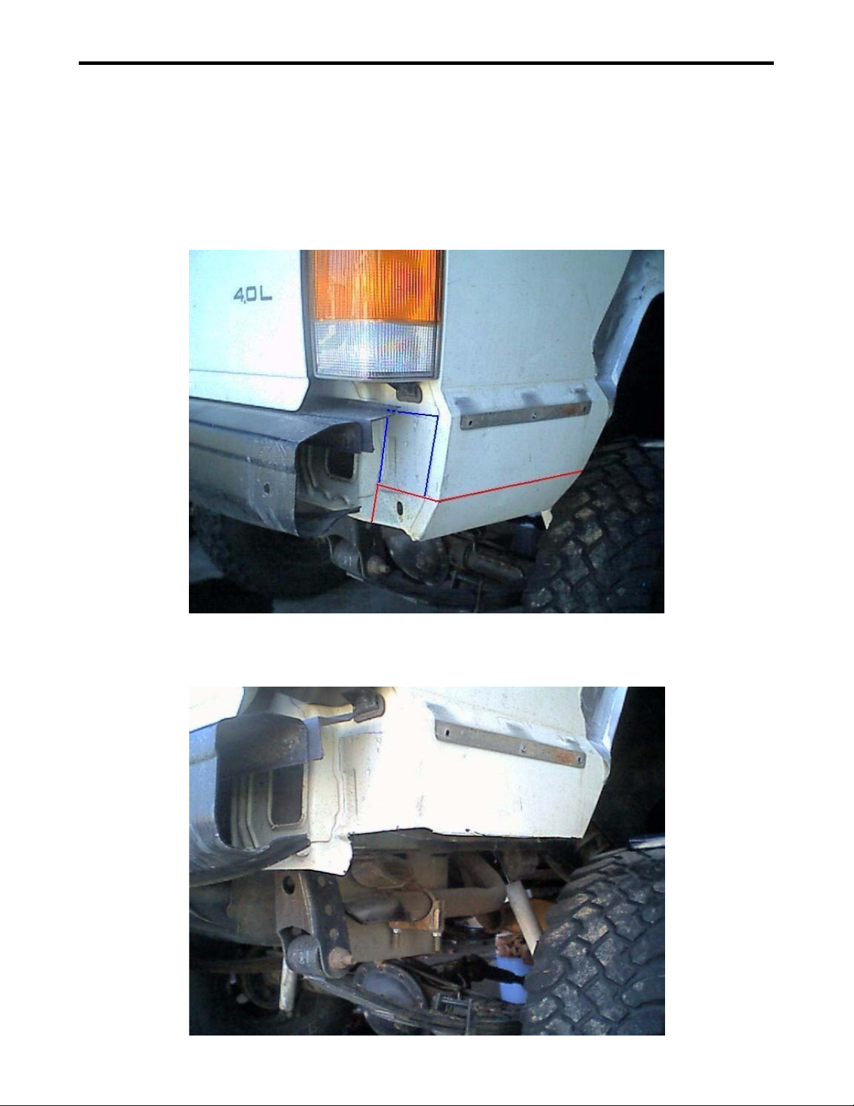
“Cut & Fold” Cherokee Rear Quarter Panels
The Cherokee rear quarter panels are not only prone to damage from obstacles encountered off-road,
but rust as well. This common modification is necessary for our “Comp Cut” rear bumpers. It does not
require any special tools or welders. If you have any questions, please contact our tech department.
Step 1: The photo below will demonstrate where to cut each panel. The lighter line represents where
you would cut all the way around the panel. The darker line represents where to cut in step 3.
Step 2: Here is what it should look like when you have cut all the way around the lower quarter panel:
5 XJ HD Rear “COMP CUT” Bumper - Kit 83245
Page 6
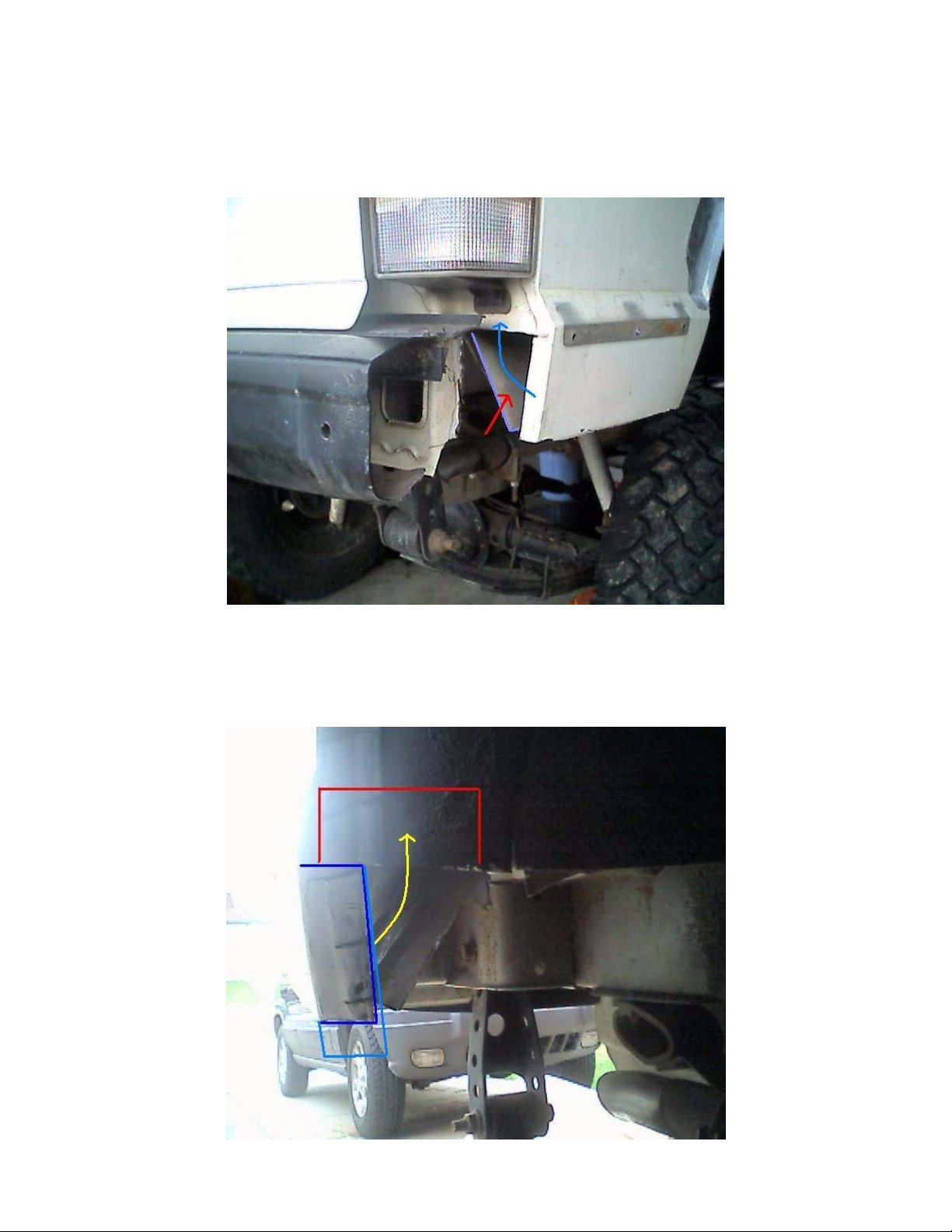
Step 3: Next Step is to cut where that darker line was shown in the first picture; which will result in the
photo below: (Note: You will need to cut through the inner part of the fender as well.)
Step 4: The lighter arrow shows how that outside piece will fold up in a later step. The inner section that
is shown after cutting is shown with a darker arrow pointing towards it; this piece folds up flat towards
the inside of the lower quarter panel:
Step 5: The photo below represents the inner part of the fender after being cut. The darker outlined
piece is the section that will fold up and relocate where the lighter outlined box is shown:
6 XJ HD Rear “COMP CUT” Bumper - Kit 83245
Page 7
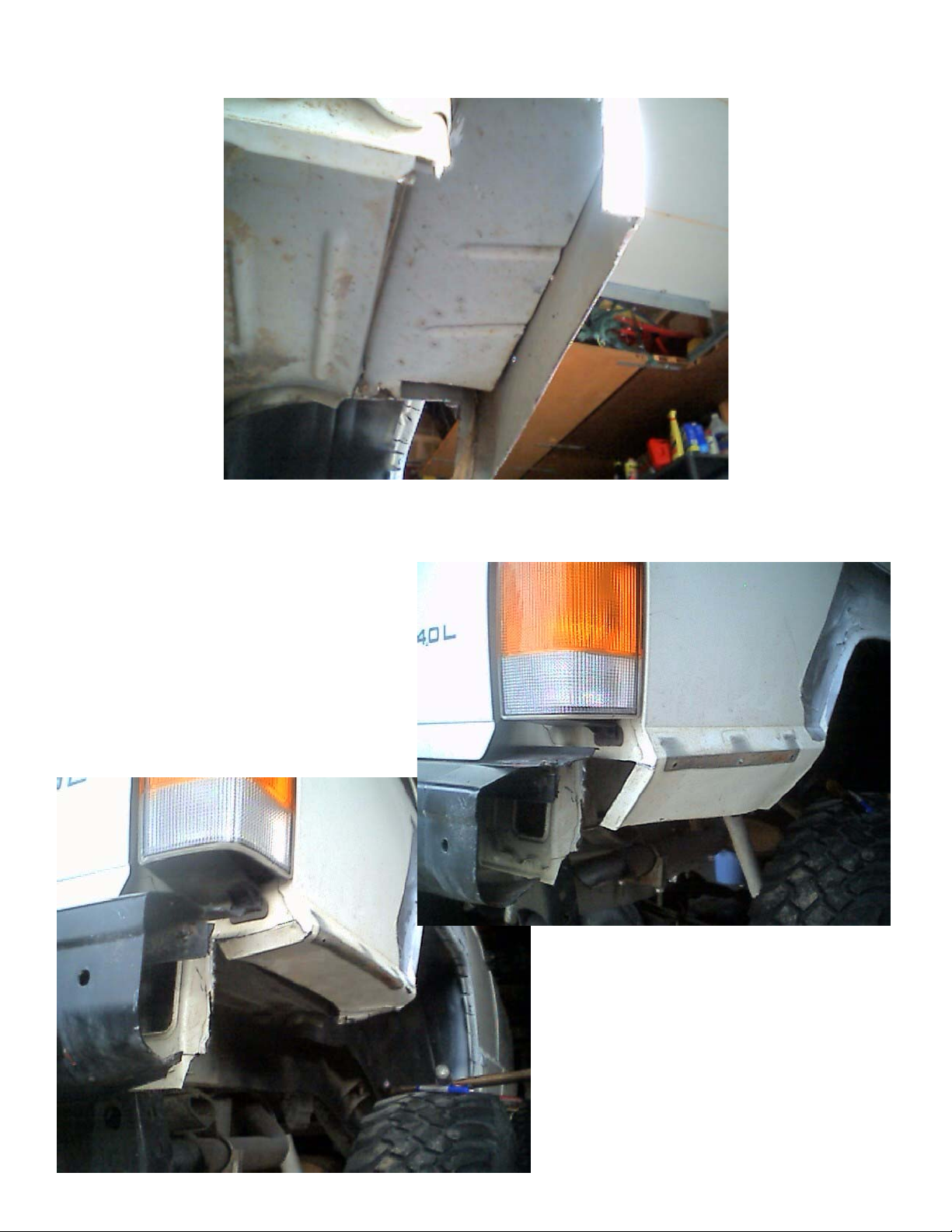
Step 6: The photo below represents the inner piece being folded up and preparing to fold up the outer
section:
Step 7: Continue folding up the outer sections as shown below:
7 XJ HD Rear “COMP CUT” Bumper - Kit 83245
Page 8
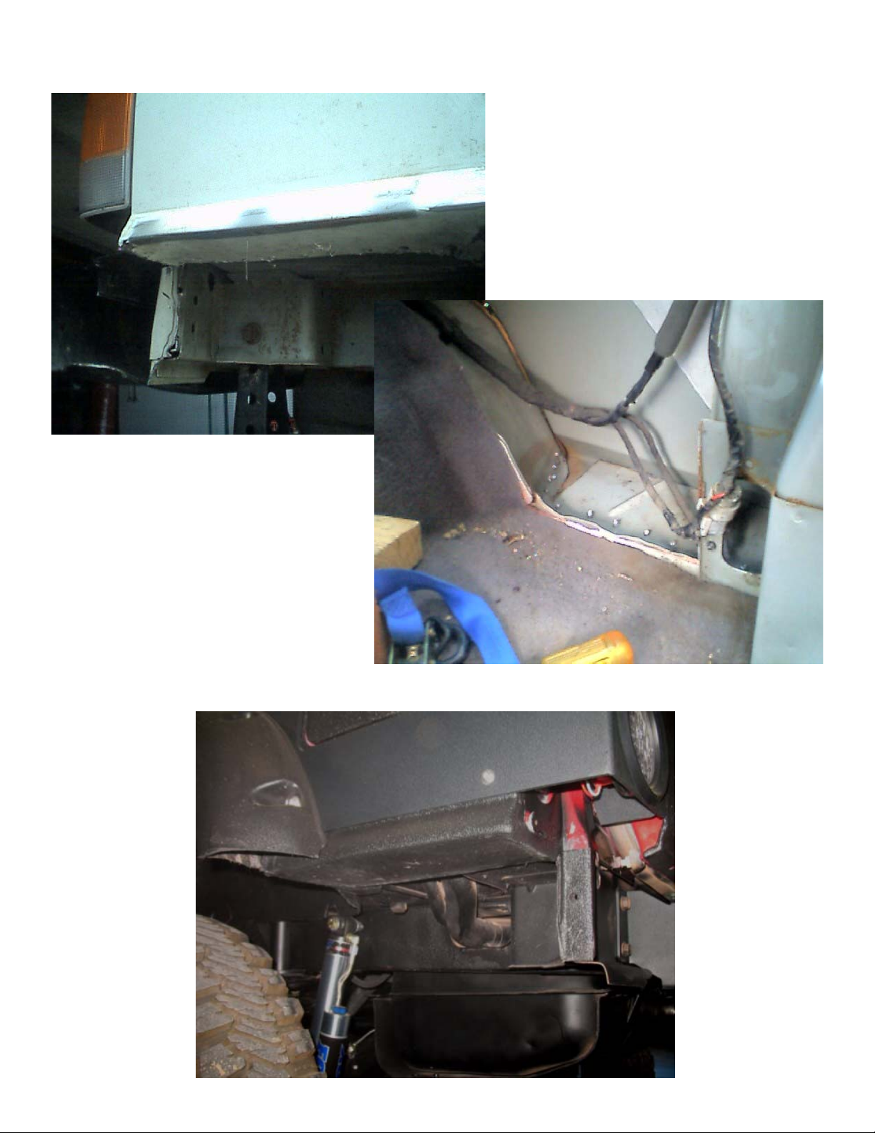
Step 8: The following photo’s shown is the inner and outer sections all folded up and ready to be “pop
riveted”, welded or bolted together followed by some sealant and a top coat of paint to prevent rust:
Finished results will “very” due to the skill level and patience of each fabricator.
8 XJ HD Rear “COMP CUT” Bumper - Kit 83245
 Loading...