

Page 1
Before Starting Installation
NOTE
Kit parts are prefaced by the word kit and appear in
bold print.
3651 N Highway 89 • Chino Valley, AZ 86323
(928) 636-7080 • www.p-a-g.net
JEEP CHEROKEE, WAGONEER
(XJ) HD FRONT BUMPER
INSTALLATION INSTRUCTIONS
1984-2001 KIT# 83240
1984-2001 W/ HOOP KIT# 83241
WARNING
Before you install this kit, read and understand all
instructions, warnings, cautions, and notes in this
instruction sheet and in the vehicle owner’s manual.
CAUTION
Proper installation of this kit requires knowledge of the
factory recommended procedures for removal and
installation of original equipment components. We recommend that the factory shop manual and any special
tools needed to service your vehicle be on hand during
the installation. Installation of this kit without proper
knowledge of the factory recommended procedures
may affect the performance of these components and
the safety of the vehicle. We strongly recommend that
a certified mechanic familiar with the installation of similar components install this kit.
WARNING
1. Carefully read all warnings and instructions completely before beginning.
2. Verify all parts have been received in this kit by
checking the parts list at the end of this document.
NOTE
If parts are missing from kit, please be prepared to provide the following information:
1. Name of purchase location
2. Bar Code on side of box
3. Date above bar code
4. Date inside box cover
5. Inspector # from inside box cover
3. Only install this kit on the vehicle for which it is
specified. If anytime during the installation you
encounter something different from what is outlined
in the instructions, call technical support at (928)
636-7080.
NOTE
OR-Fab HD front winch bumper will ONLY mount
8000lb (WARN M8000). “low profile” remote winches.
9500lb. winches will fit with minor modifications to the
lower core support depending on size.
Many states and municipalities have laws restricting
bumper heights and vehicle lifts. Consult state and
local laws to determine if the changes you intend to
make to the vehicle comply with the law.
WARNING
Always wear eye protection when operating power
tools.
WARNING
Before you install this kit, block the vehicle tires to prevent the vehicle from rolling.
NOTE
Performance Automotive Group recommends using
the Loctite® supplied in the kit on the threads of all kit
nuts and bolts unless specified otherwise in these
instructions.
4. Special tools needed:
a. Die grinder or similar tool capable of cutting
metal and plastic.
b. 7/32” drill bit
Engine Compartment
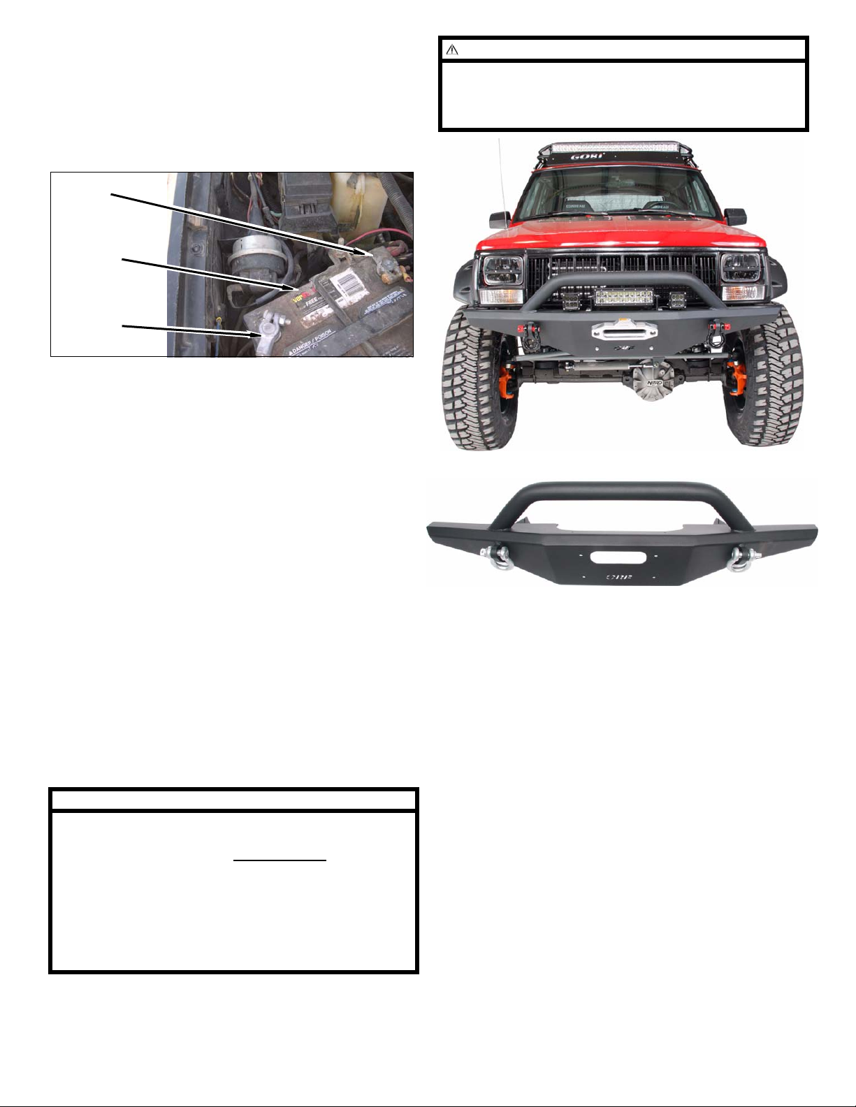
1. Disconnect both battery cables. Disconnect negative
cable first, then positive cable.
Positive
Cable
Battery
Negative
Cable
1 ‘84-’01 XJ Front Bumper - Kit 83240, 83241
Page 2
Prepare to Install Kit
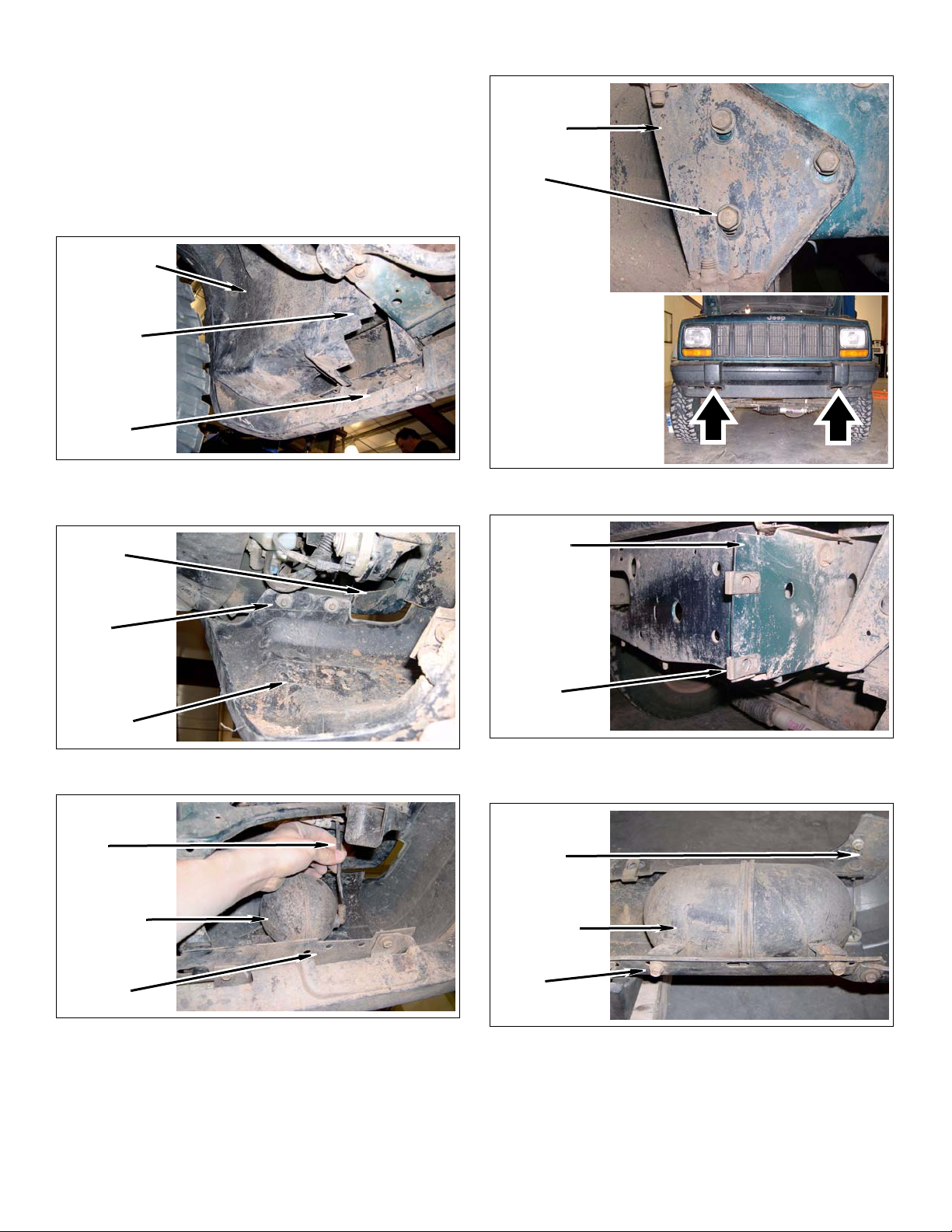
d. Remove six bolts and bumper from vehicle.
Front of Vehicle
1. Bumper
a. 1997-2001 Models: Remove push clips and pull
back wheel well liner from front bumper.
Wheel Well
Push Clip
Front
Bumper
b. 1997-2001 Models: Remove four bolts from
front bumper and two fenders.
Fender
Front
Bumper
Bolts
e. Remove four c-clip fasteners from vehicle.
Unibody
Bolts
Front
Bumper
c. Disconnect vacuum line from vacuum reservoir.
Vacuum
Line
Vacuum
Reservoir
Front
Bumper
C-Clips
f. 1984-1996 Models: Remove two bolts and vac-
uum reservoir from bumper.
Front
Bumper
Vacuum
Reservoir
Bolts
2 ‘84-’01 XJ Front Bumper - Kit 83240, 83241
Page 3
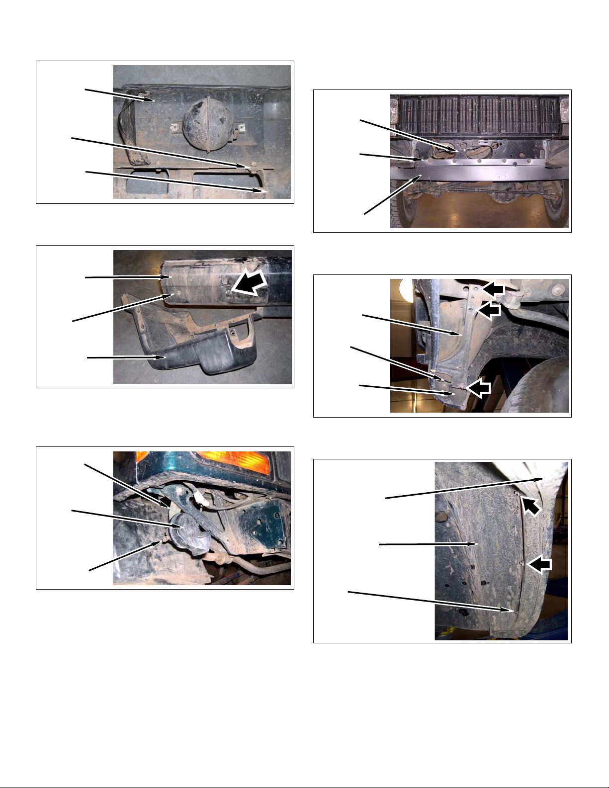
g. 1997-2001 Models: Remove two bolts, two
nuts, and bumper corner cover from bumper.
Front
Bumper
Bolts &
Nuts
Bumper
Corner Cover
h. 1997-2001 Models: Remove two torx bolts and
vacuum reservoir from bumper.
Front
Bumper
Torx
Bolts
3. 1984-1996 Models: Lower valence & fender flares
a. Remove five screws from lower valence and
core support.
Core
Support
Screws
Lower
Valence
b. Remove eight bolts and two lower valence sup-
ports from two fenders and core support.
Lower
Valence
Support
Bumper
Corner Cover
2. Horns
a. Disconnect two wire harnesses from two horns.
Bracket
Horn
Wire
Harness
b. Remove two bolts, two brackets, and two horns
from vehicle.
Bolts
Fender
c. Remo ve six nuts from two front wheel wells and
pull two fender flares away from front of fenders.
Fender Flare
Wheel Well
Nuts
3 ‘84-’01 XJ Front Bumper - Kit 83240, 83241
Page 4
4. Remove three steering box bolts and washers from
driver side unibody and steering box.
WARNING
Bolts &
Washers
Unibody
Steering
Box
Install Kit
Engine Compartment
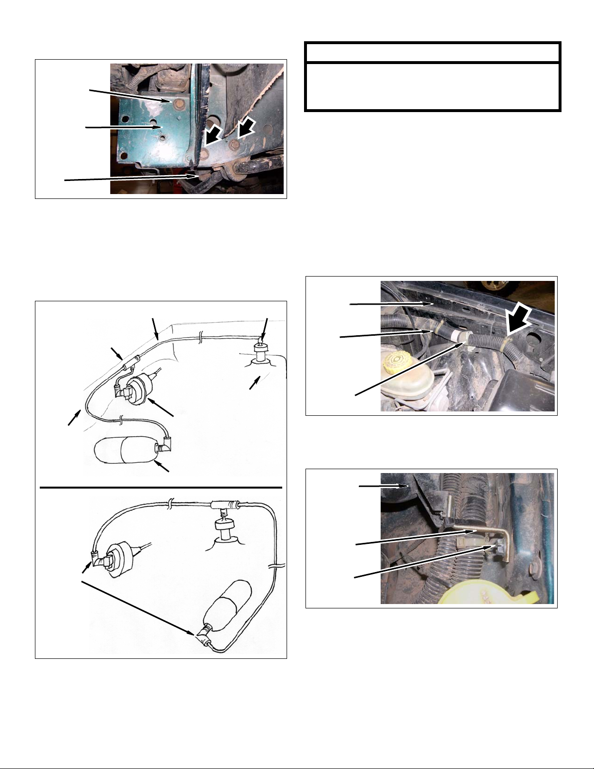
1. Cruise Control Models: Vacuum lines
BEFORE
T-Connector
Manifold Line
V acuum fittings and lines may have become brittle over
time. Use care when handling fittings and vacuum
lines. If necessary, use le ngths of kit line (vacuum) in
place of cracked or damaged vacuum line.
a. Remove line from cruise control fitting and t-con-
nector.
b. Remove T-connector from reservoir line and
manifold line.
c. Trim manifold line, if necessary, and install onto
cruise control fitting.
d. Remove wiring harness and clips from driver
side inner fender.
Inner
Fender
Check Valve
Clips
Reservoir
Line
AFTER
Fitting
*Not To Scale
Intake Manifold
Cruise Control
Vacuum Reservoir
Wiring
Harness
e. Install two kit bracket (2” step) onto driver side
inner fender with two kit bolts (5/16” x 3/4” self-
tapping). DO NOT TIGHTEN.
Vacuum
Reservoir
Kit Bracket
(2” Step)
Kit Bolt
(5/16” x 3/4”)
4 ‘84-’01 XJ Front Bumper - Kit 83240, 83241
Page 5
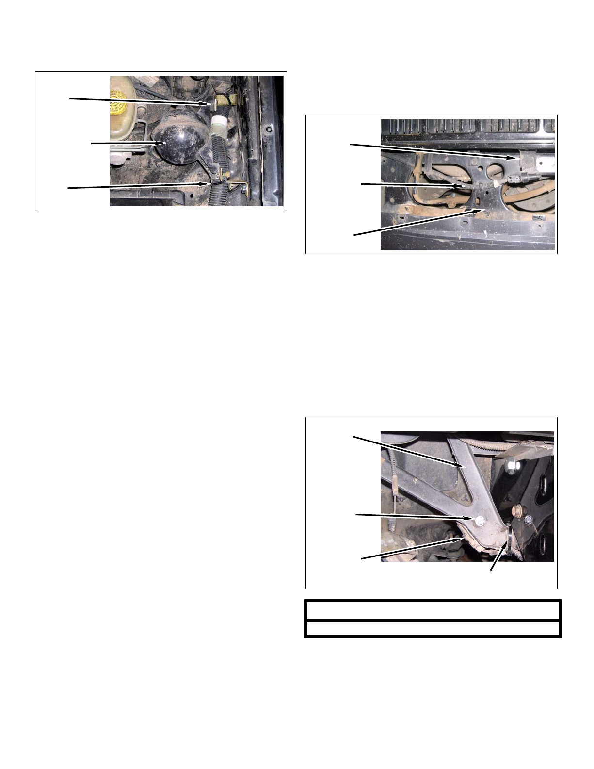
f. Install vacuum reservoir onto two kit brackets
(2” step) with two factory c-clips and bolts. DO
NOT TIGHTEN.
Front of Vehicle
1. Air temp sensor
C-Clips &
Bolts
Vacuum
Reservoir
Kit Ties
(Zip)
g. Install wiring harness onto two kit brackets (2”
step) with two kit ties (zip).
h. TIGHTEN two kit bolts (5/16” x 3/4”) and two
factory bolts.
i. Remove manifold line and fitting from check
valve and intake manifold.
j. Install T-connecto r onto check valve.
a. Remove bolt and sensor from core support.
Install bolt back into core support.
Bolt &
Sensor
Wiring
Harness &
Clip
Core
Support
b. Disconnect wiring harness from sensor.
c. Remove sensor wiring harness and clip from
core support.
d. Route wiring harness connector next to passen-
ger side horn.
k. Install manifold line into T-connector.
l. Install vacuum reservoir line into T-connector
and route vacuum reservoir line to vacuum reservoir.
m. Trim vacuum reservoir line, if necessary. Install
vacuum reservoir line onto vacuum reservoir
with rubber fitting.
2. Non-Cruise Control Models: Vacuum lines
a. Repeat above steps, ignoring cruise control pro-
cedures.
e. Install sensor onto passenger side bracket with
kit bolt (1/4” x 1”), two kit washers (1/4” SAE),
and kit nut (1/4” Nylock).
Bracket
Kit Bolt
(1/4” x 1”),
Kit Washers
(1/4” SAE),
Kit Nuts
(1/4” Nylock)
Sensor &
Wiring Harness
NOTE
Drill 1/4” hole into bracket, if necessary.
Kit Tie (Zip)
f. Connect wiring harness onto sensor.
g. Install wiring harness onto bracket with kit tie
(zip).
5 ‘84-’01 XJ Front Bumper - Kit 83240, 83241
Page 6
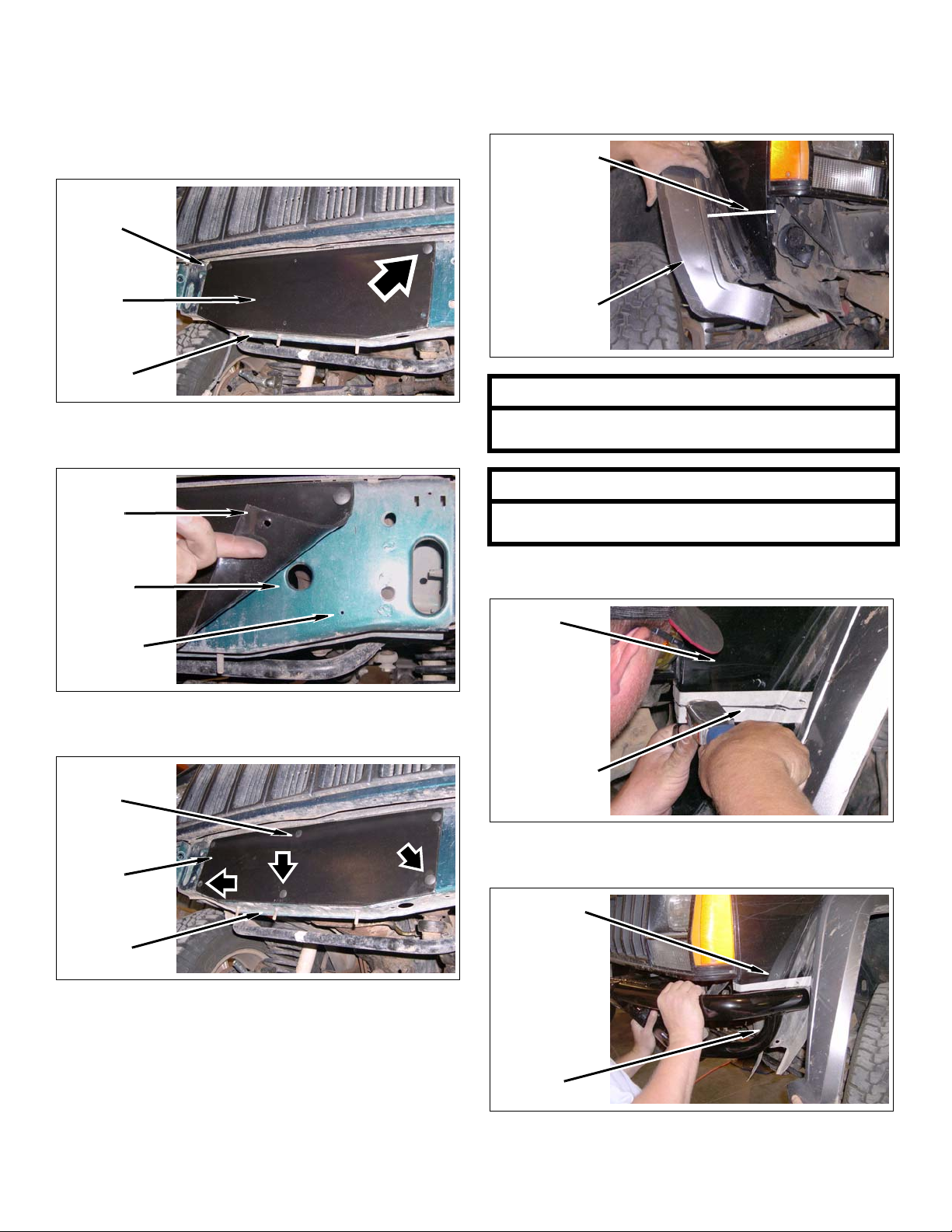
2. Gap guard
a. Install kit gap guard, dull side out, onto core
support with two kit clips (push) through top
driver and passenger holes of kit gap guard and
corresponding holes in core support.
Kit Clips
(Push)
Kit Gap
Guard
Core
Support
a. Position kit corner (driver) onto kit bumper
(center) and using kit corner (driver) as a guide,
mark fender approximately 1” below side
marker.
Mark Fender
Fender Flare
NOTE
b. Drill four 7/32” holes into core support corre-
sponding to kit gap guard holes.
Kit Gap
Guard
Core
Support
Drill Here
c. Install 4 kit clips (push) into previously drilled
holes.
Kit Clip
(Push)
Kit Gap
Guard
For proper fender flare retention, attempt to cut fender
flare and bracket BELOW fender flare bracket stud.
NOTE
Further trimming of the fender and fender flare may be
required for desired fitment.
b. Cut fender along marked line.
Fender
Marked Line
c. Test fit kit corner (driver) onto kit bumper (cen-
ter).
Core
Support
3. 1984-1996 Models: Driver fenders
Cut Fender
Kit Bumper
(Driver)
6 ‘84-’01 XJ Front Bumper - Kit 83240, 83241
Page 7
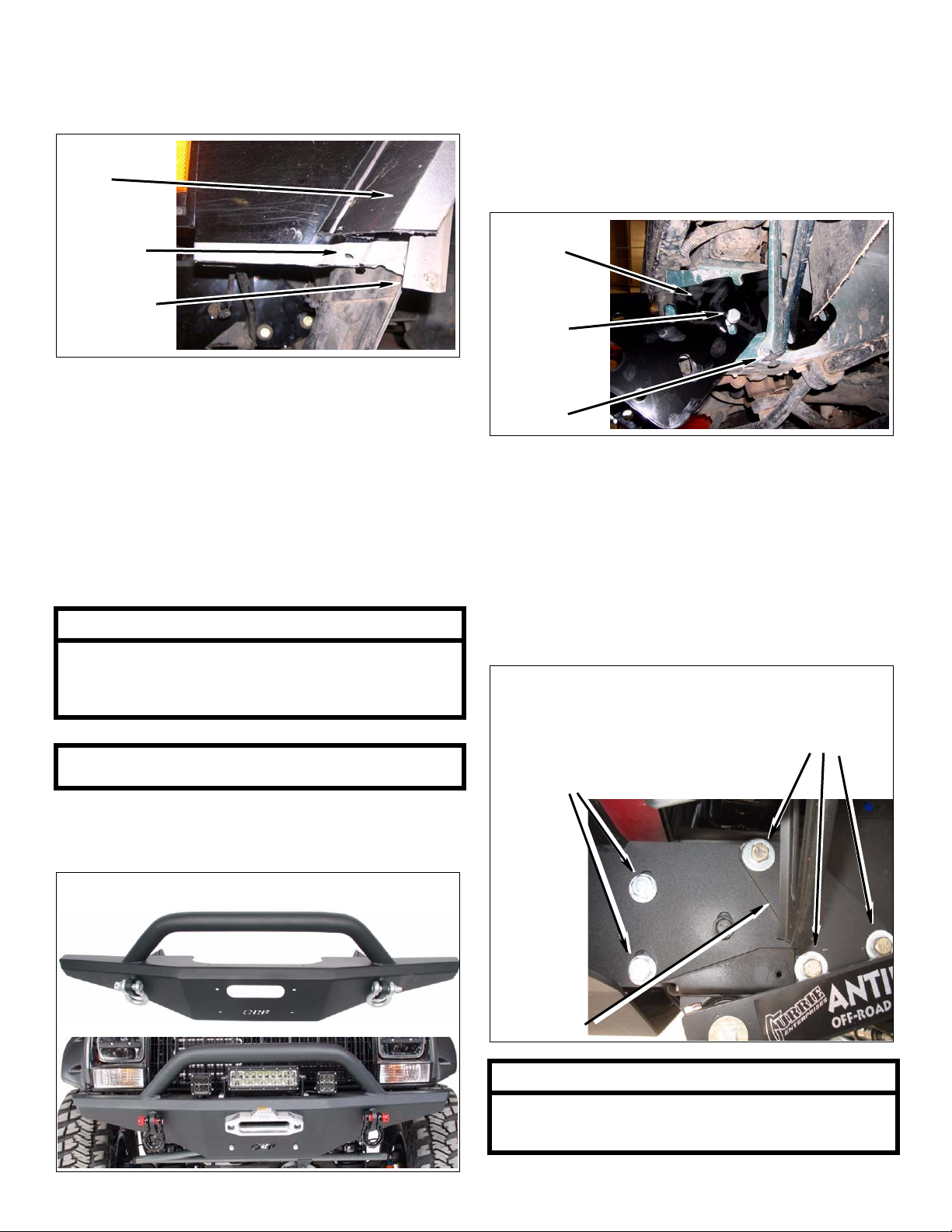
d. Mark and cut fender flare and fender flare
bracket along marked line for desired fit.
Remove lower valence along with cut portions of
fender flares.
Bumper
1. Installing bumper
Cut Fender
Flare
Fender Flare
Stud Hole
Cut Fender
Flare Bracket
e. Install fender flare and fender flare bracket onto
fender with nut, if possible.
f. Repeat above steps for kit corner (passenger)
Winch
1. Install winch
a. Install kit bumper onto unibody with two kit
bolts (10mm x 40mm), and two kit washers
(10mm). DO NOT TIGHTEN.
Kit Bumper
(Center)
Kit Bolt
(10mm x
40mm),
Kit Washer
(10mm)
Unibody
b. Apply a small amount of kit Loctite® (6ml bottle)
onto threads of three kit bolts (7/16” x 4-1/2”)
and install kit bracket (steering box), kit
bumper, steering box, and steering box spacer
onto unibody with three kit bolts (7/16” x 4-1/2”)
and three washers. DO NOT TIGHTEN.
NOTE
OR-Fab HD front winch bumper will ONLY mount
8000lb. “low profile” remote winches. 9500lb. winches
will fit with minor modifications to the lower core support.
Winch supplied mounting bolts may not be sufficient in
length.
a. Mount winch prior to installing bumper onto XJ.
Note: Besure to mount winch with line feed on top
Mount Winch
c. Install two kit bolts (1/2” x 1-1/2”), two kit wash-
ers (1/2” SAE), and two kit nuts (1/2” flange)
onto kit bumper and drivers side unibody.
Kit Bolts
(1/2” x 1-1/2”),
Kit Washers
(1/2” SAE),
Kit Nuts
(1/2” Flange)
Kit Bracket
(Steering
Box)
Kit Bolts
(7/16” x 4-1/2”),
Washers
NOTE
A spacer exists between unibody and steering box.
Ensure kit bolts (7/16” x 4-1/2”) are installed through
steering box spacer.
7 ‘84-’01 XJ Front Bumper - Kit 83240, 83241
Page 8
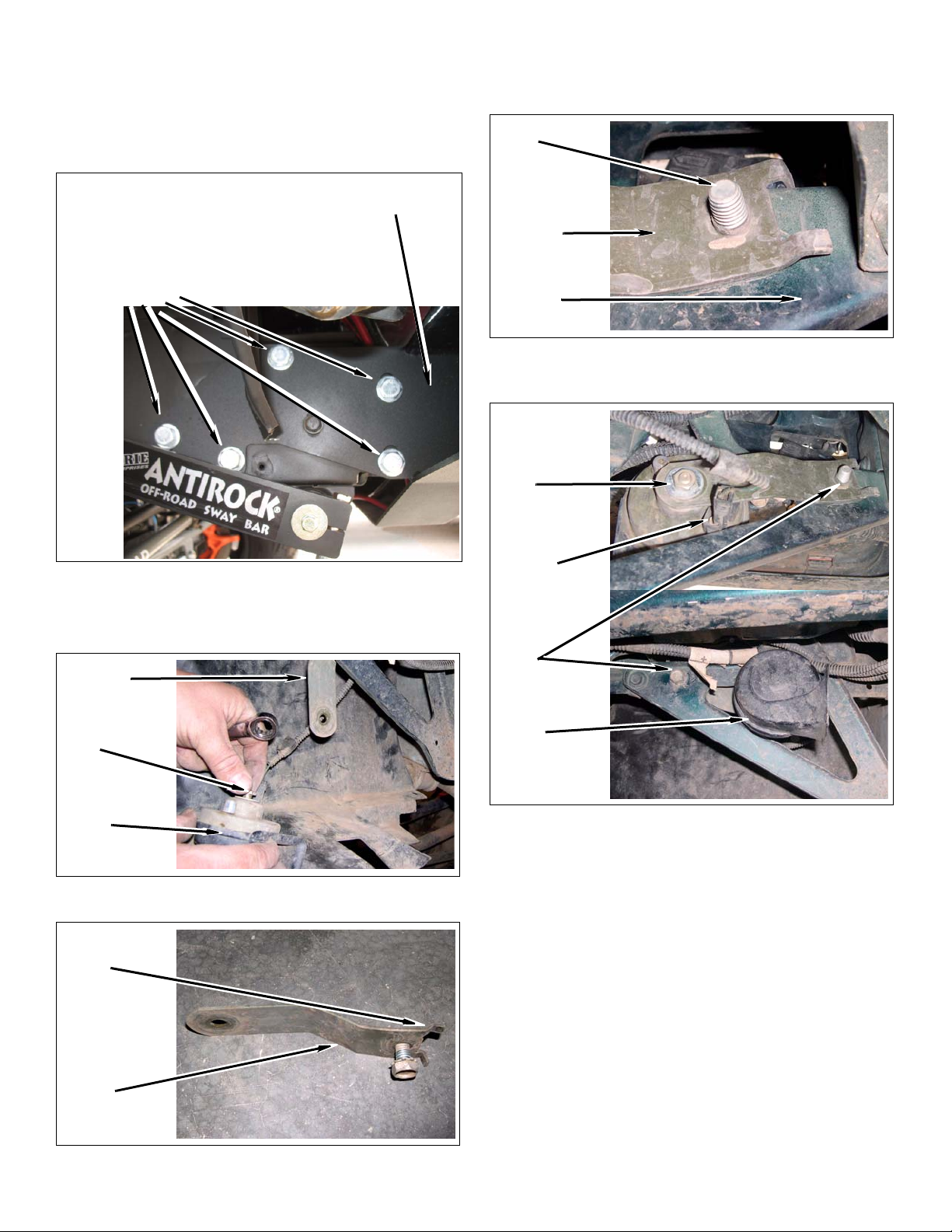
d. Install five kit bolts (1/2” x 1-1/2”), five kit wash-
ers (1/2” SAE), and five kit nuts (1/2” flange)
onto kit bumper and passenger side unibody.
Magnet may be used, through the front access
hole, to feed kit flange nuts (1/2”) into unibody.
DO NOT TIGHTEN.
c. Install bracket onto vehicle with bolt. DO NOT
TIGHTEN. Ensure bracket is positioned as
shown.
Bolt
Kit Bolts
(1/2” x 1-1/2”),
Kit Washers
(1/2” SAE),
Kit Nuts
(1/2” Flange)
2. Driver side horn
a. Remove nut and bracket from horn.
Kit Bumper
Horn
Bracket
Vehicle
d. Install horn onto bracket with nut. TIGHTEN bolt
and bracket onto vehicle.
BACKSIDE
Nut
Wiring
Harness
Bracket
Nut
Horn
b. Bend bracket tab as shown.
Bend Tab
Back
Horn
Bracket
Bolt
Horn
FRONTSIDE
e. Install wiring harness onto horn.
f. Repeat above steps for passenger side horn.
8 ‘84-’01 XJ Front Bumper - Kit 83240, 83241
Page 9
After Completing Installation
Engine Compartment
1. Connect both battery cables. Connect positive cable
first, then negative cable.
Positive
Cable
Battery
Negative
Cable
Miscellaneous
1. Check all fasteners to ensure they are tight.
CAUTION
Performance Automotive Group does not recommend
any particular wheel and tire combinations for use with
its bumpers and cannot assume responsibility for the
customer’s choice of wheels and tires.
2. Ensure all wires, hoses, cables, etc. are properly
connected and there is ample slack.
3. Check vacuum system for leaks.
Dynamic Vehicle Check
1. Check steering and suspension in all positions to
ensure that there is no bind and adequate clearance
between all moving, fixed, and heated members.
Check tire-to-bumper clearance and ensure no contact in any position. Check battery connections and
electrical component operations. Test-drive vehicle .
Check cruise control, if equipped, and all vacuum
controlled vehicle systems. If vacuum leaks are
found, correct immediately.
NOTE
All warranty information, instruction sheets, and other
documents regarding the installation of this product
must be retained by the vehicle owner
contained in the instructions and on the warranty card
will be required for any warranty claims. The vehicle
owner needs to understand the modifications made to
the vehicle and how they affect vehicle handling and
performance. Failure to provide the customer with this
information can result in damage to the vehicle and
severe personal injury.
. Information
9 ‘84-’01 XJ Front Bumper - Kit 83240, 83241
Page 10
Kit Parts List
Qty. Description
Kit 83240 & 83241
1 Bracket (Steering Box)
1 Bumper (Main)
1 Gap guard
1 Line (Vacuum)
1 ZH83240 (Hardware Bag Kit)
2 Bracket (2” step)
2 Bolt (10mm x 40mm)
1 Bolt (1/4” x 1”)
2 Bolt (5/16” x 3/4” self-tapping)
3 Bolt (7/16” x 4-1/2”)
7 Bolt (1/2” x 1-1/2”)
6 Clip (push)
1 Loctite® (6ml bottle)
1 Nut (1/4” Nylock)
7 Nut (1/2” flange)
4 Tie (zip)
2 Washer (10mm)
2 Washer (1/4” SAE)
3 Washer (7/16” USS)
7 Washer (1/2” SAE)
NOTE
Depending on the vehicle configuration some parts
may not be used.
Rev. 00, Copyright 5/12
Performance Automotive Group
www.p-a-g.net
10 ‘84-’01 XJ Front Bumper - Kit 83240, 83241
 Loading...