

Page 1

1
EN
Wireless Pro Weather Station
with USB upload
Model: WMR88 / WMR88A
USER MANUAL
CONTENTS
Introduction ............................................................... 1
Packaging contents .................................................. 1
Base station ........................................................... 1
Wind sensor ..........................................................1
Temperature & humidity sensor ............................. 1
Rain gauge ............................................................. 2
Accessories - Sensors ............................................. 2
Overview .................................................................... 2
Top view .................................................................2
Back view ............................................................... 2
LCD display ............................................................ 2
Wind sensor ...........................................................3
Rain gauge ............................................................. 3
Outdoor temperature / humidity sensor .................. 3
Getting started .......................................................... 3
Set up remote wind sensor ....................................
3
Set up remote temperature / humidity sensor ........
4
Set up rain gauge ...................................................
4
Set up base station ................................................
4
Verify connection ......................................................4
Wind sensor ...........................................................
5
Temperature / humidity sensor ...............................
5
Rain gauge .............................................................
5
Mounting / placing of sensors ................................. 5
Wind sensor ...........................................................5
Temperature / humidity sensor ...............................
5
Rain gauge ............................................................. 5
Clock reception ......................................................... 6
Clock / Calendar ....................................................... 6
Moon phase ............................................................... 6
Auto scanning function ........................................... 7
Weather forecast ...................................................... 7
Temperature and humidity .......................................7
Temperature and humidity trend ............................
7
Wind chill / direction / speed ................................... 7
UVI / Barometer / Rainfall ......................................... 8
UV Index ................................................................ 8
Barometer .............................................................. 8
Rainfall ...................................................................9
Upload data to PC software ..................................... 9
Backlight ................................................................... 9
Reset .......................................................................... 9
Specifications ...........................................................9
Precautions ............................................................. 10
About Oregon Scientific ........................................ 10
EU declaration of conformity ................................ 10
FCC statement ........................................................ 11
INTRODUCTION
Thank you for selecting the Oregon Scientific™ Wireless
Pro Wea ther Statio n with USB upload (WM R88 /
WMR88A).
The base station is compatible with other sensors. To
purchase additional sensors, please contact your local
retailer.
Sensors with this logo are compatible with this
unit.
NOTE Please keep this manual handy as you use
your new product. It contains practical step-by-step
instructions, as well as technical specifications and
warnings you should know about.
PACKAGING CONTENTS
BASE STATION
1
1 x base station
4 x AA
UM-3 1.5V batteries
1 x USB cable
1 x 6V adaptor
WIND SENSOR
TEMPERATURE & HUMIDITY SENSOR
1 x wind sensor (1
x wind vane above
and 1 x anemometer
below)
1 x sensor
connector
2 x AA UM-3
1.5V batteries
4 x screws
(Type A)
1 x round
U- bolt
2 x AAA UM-4
1.5V battery
1 x wall mount
bracket
1 x temperature /
humidity sensor
1 x table stand
Page 2

2
EN
RAIN GAUGE
ACCESSORIES - SENSORS
This product can work with up to 3 sensors at any one
time to capture outdoor temperature, relative humidity or
UV readings in various locations.
Optional wireless rem ote sen sor s such as tho se
listed below can be purchased separately. For more
information, please contact your local retailer.*
• Solar Panel STC800 connectable to Wind Sensor and
Temperature / humidity sensor
• Thermo-hygro THGR800 (3-Ch)
• Thermo-hygro THGR810 (10-Ch)
• UV UVN800
• Pool sensor THWR800
* Features and accessories will not be available in
all countries.
OVERVIEW
TOP VIEW
LIG HT
1 2 3 4 5 6
1. UP / DOWN: Increase / decrease values of the selected
setting; toggle between indoor / outdoor channels
2. MODE: Switch between the different display modes
/ settings; set clock; set altitude; activate autoscan
3. MAX / MIN: Read the max / min memory readings;
clear readings
4. SELECT: Switch between the different areas
5. UNIT: Select unit of measurement
6. LIGHT: Activate backlight
BACK VIEW
EU/UK
1
2
3
4
5
6
7
2 x AA UM-3
1.5V batteries
4 x screws
(Type B)
1 x rain collector
1. Wall mount holes
2. Battery compartment
3. SEARCH: Searches for sensors or for the radiocontrolled clock signal
4. RESET: Returns unit to default settings
5. EU / UK switch: Select the nearest radio signal
(WMR88 only)
6. USB socket
7. AC adapter socket
LCD DISPLAY
1
1
3
2
A
4
B
C
D
1. USB: indicates a successful USB connection
2. : Main unit battery low
3. : No main power supply
4. Weather forecast
A. Temperature / Humidity / Dew Point Area
B. Wind Speed / Wind Direction / Wind Chill Area
C. UVI / Barometer / Rainfall Area
D. Clock / Calendar
/ Moon Phase Area
A Temperature / Humidity / Dew Point Area
1
2
7
8
9
3
6
5
4
10
11
1. Temperature trend
2. MAX / MIN temperature is displayed
3. Indoor / Outdoor channel temperature and
humidity is displayed
4. Temperature area selected
5. Outdoor sensor battery is low
6. Temperature reading (°C / °F)
7. Humidity / Dew point area selected
8. Dew point level – Temperature is displayed
9. MAX / MIN humidity / dew point level is displayed
10. Humidity trend
11. Humidity reading
B Wind Speed / Wind Direction / Wind Chill Area
1
2
3
4 5
6
1. Wind speed reading (m/s, kph, mph or knots)
6 x washers
Page 3

3
EN
2. Outdoor wind sensor battery is low
3. Wind speed level indicator
4. Wind speed level description
5. Minimum wind chill is displayed
6. Wind direction display
C UVI / Barometer / Rainfall Area
1
1
3
4
5 6 2 7
1. UVI / barometer / rainfall reading is displayed
2. Past 24hrs rainfall is displayed
3. Outdoor UV / rain sensor battery is low
4. UVI / barometric pressure (mmHg, inHg or mb) /
rainfall readings (in or mm) for the current hour
5. UVI level indicator
6. Maximum UV is displayed
7. UVI / barometric pressure / rainfall historical bar chart
display
D Clock / Calendar / Moon Phase Area
1
3 64 5
2
1. AM / PM
2. Time zone offset
3. Timestamp is displayed
4. Clock signal reception indicator
5. Time / date / calendar
6. Moon phase
WIND SENSOR
1
2
3
4
1. Wind direction
2. Wind vane casing
3. Anemometer
4. Solar power socket
RAIN GAUGE
Base and funnel:
1
2
3
1. Rain gauge
2. Battery compartment
3. RESET button
1
2
1. Funnel
2. Indicator
OUTDOOR TEMPERATURE / HUMIDITY
SENSOR
1
5
2
3
4
C F
1. LED status indicator
2. RESET hole
3. °C / °F: Select temperature unit
4. CHANNEL switch
5. Battery compartment
GETTING STARTED
NOTE Install batteries in the remote sensors before the
base station matching the polarities (+ and -).
NOTE Use alkaline batteries for longer usage and
consumer grade lithium batteries in temperatures below
freezing.
SET UP REMOTE WIND SENSOR
The win d sens or takes wind spe ed and directi on
readings.
The sensor is battery operated. It is capable of transmitting
data to the base station wirelessly within an approximate
operating range of 100 meters (328 feet).
Page 4
4
EN
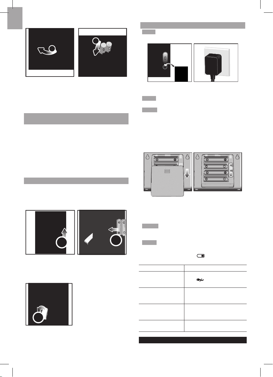
To insert batteries:
1
2
1. Unscrew the anemometer from the wind sensor
carefully.
2. Insert batteries matching the polarities (+ / -) and
replace the anemometer. Press
RESET after each
battery change.
SET UP REMOTE TEMPERATURE / HUMIDITY
SENSOR
The remote sensor can collect data from up to 3 channels.
To set up the remote sensor:
1. Slide open the battery door.
2. Slide channel switch to select a channel (1, 2, 3).
Ensure you use a different channel for each sensor.
3. Insert the batteries, matching the polarities (+ / -).
4. Press
RESET after each battery change.
5. Close the battery door.
SET UP RAIN GAUGE
The rain gauge collects rain and takes rainfall readings.
The sensor can remotely transmit data to the base
station.
To set up the rain gauge:
2
1
1. Remove screws and slide the cover off in an upwards
motion.
2. Insert the batteries (2 x UM-3 / AA), matching the polarities
(+ / -). Press RESET after each battery change.
3
3. Remove the fibre tape.
SET UP BASE STATION
NOTE Install batteries in the remote sensors before the
base station matching the polarities (+ and -).
For continuous use, please install the AC adaptor. The
batteries are for back-up use only.
NOTE Make sure the adaptor is not obstructed and is
easily accessible to the unit.
NOTE The base station and adaptor should not be
exposed to wet conditions. No objects filled with liquid,
such as vases, should be placed on the base station
and adaptor.
To completely disconnect from power, unplug adaptor
from the mains.
To insert batteries:
EU/UK
1. Slide open the battery door.
2. Insert the batteries, matching the polarities (+ / -).
3. Press
RESET after each battery change.
4. Close the battery door.
NOTE Do not use rechargea ble batter ies . It is
recommended that you use alkaline batteries with this
product for longer performance.
NOTE Batteries should not be exposed to excessive
heat such as sunshine or fire.
The battery icon indicator may appear in the
following areas:
AREA MEANING
Weather Forecast
Area
Battery in the base station is
low.
will show when AC
adaptor is disconnected.
Temperature or
Humidity Area
The displayed channel
indicates the outdoor sensor
for which battery is low.
Wind Speed / Wind
Direction / Wind Chil
Area
Battery in the wind sensor
is low.
UVI / Barometer /
Rainfall Area
Battery in the UV / Rain
sensor is low.
VERIFY CONNECTION
Before proceeding to install sensors outside, please verify
communication to the base station.
Page 5
5
EN
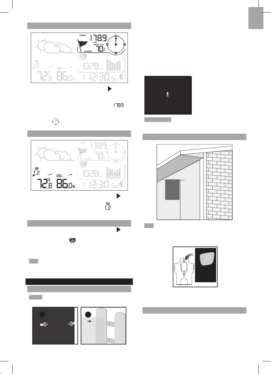
WIND SENSOR
Press SELECT until the selected area icon is in the
top right display area.
• Wind speed: Gently rotate the wind vane and confirm
a numerical reading on the base station, e.g.,
.
• Wind direction indicator. Move the direction of the
wind indication and verify the icon moves in the same
direction .
TEMPERATURE / HUMIDITY SENSOR
1. Press SELECT until the selected area icon is in
the bottom left display area.
2. Press UP / DOWN to select channel 1
and verify
a numerical reading.
RAIN GAUGE
1. Press SELECT until the selected area icon is in
the middle right display area.
2. Press MODE until is displayed.
3. Tilt the tipping funnel on the rain gauge several times
and verify a numerical reading on the base station.
TIP If no reading is displayed for a sensor, press the
SEARCH button on the base station to initiate a wireless
sensor search.
MOUNTING / PLACING OF SENSORS
WIND SENSOR
NOTE The sensor should be positioned in an open area
away from trees or other obstructions.
a
b
Secure the sensor connector in the desired location:
a. Align the back of the sensor connector to an existing
pole. Secure in place by inserting the ends of the
U-bolt into the holes on the sensor connector and
securing it with washers and bolts.
OR
b. Insert 4 type A screws into the holes of the sensor
connector. Screw firmly into place, i.e., fence.
Slide wind vane onto the smaller end of the sensor
connector.
IMPORTANT Ensure that the wind sensor is pointing
North to enable it to record accurate readings.
TEMPERATURE / HUMIDITY SENSOR
1.5 m (5 ft)
TIP Ideal placements for the sensor would be in any
location on the exterior of the home at a height of not
more than 1.5 m (5 ft) and which can shield it from direct
sunlight or wet conditions for an accurate reading.
Secure the sensor in the desired location using the wall
mount bracket or table stand.
RAIN GAUGE
The base station and rain gauge should be positioned
within an effective range: about 100 meters (328 feet)
in an open area.
The rain gauge should be mounted horizontally about 1
meter (3 feet) from the ground in an open area away from
trees or other obstructions to allow rain to fall naturally
for an accurate reading.
Page 6
6
EN
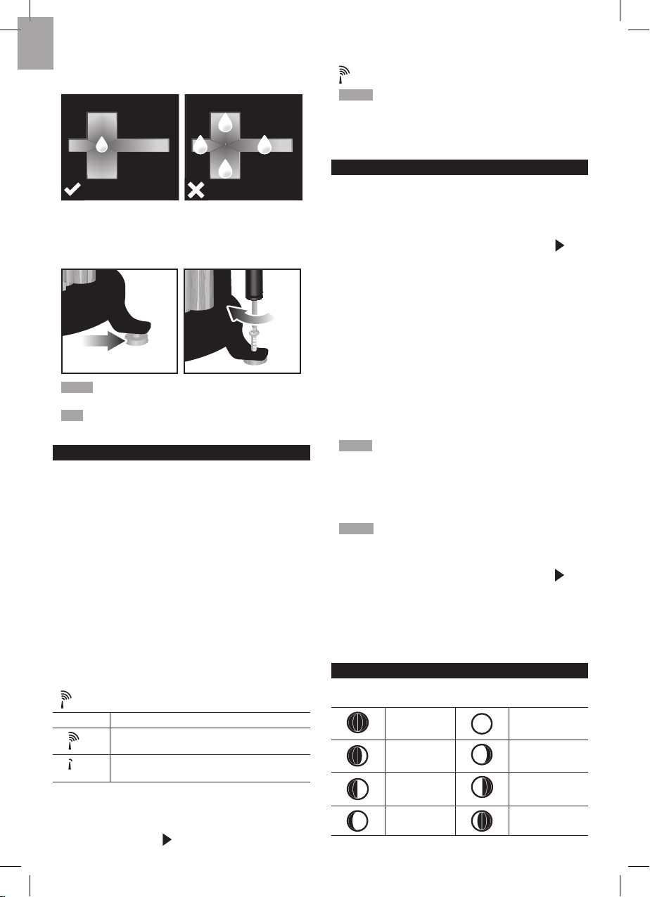
To ensure a level plane:
Put a few drops of water on the cross at the base of the
funnel to check the horizontal level.
1
23
4
Water will pool to the center of the cross when the rain
gauge is level.
If water remains on 1-4, the gauge is not horizontal.
If necessary, adjust the level using the screw.
NOTE For best results, ensure the base is horizontal to
allow maximum drainage of any collected rain.
TIP Press RESET button on base station to erase all
testing data.
CLOCK RECEPTION
This product is designed to synchronize its calendar
clock automatically once it is brought within range of a
radio signal:
WMR88:
• EU: DCF-77 signal: within 1500 km (932 miles) of
Frankfurt, Germany.
• UK: MSF-60 signal: within 1500 km (932 miles) of
Anthorn, England.
WMR88A:
• WWVB-60 signal: within 3200km (2000 miles) of Fort
Collins Colorado.
WMR88 only - slide the EU / UK switch to the appropriate
setting based on your location. Press
RESET whenever
you change the selected setting.
The reception icon will blink when it is searching for a
signal. If the radio signal is weak it can take up to 24
hours to get a valid signal reception.
indicates the status of the clock reception signal.
ICON MEANING
Time is synchronized.
Receiving signal is strong
Time is not synchronized.
Receiving signal is weak
To enable (and force a signal search when previous
search was unsuccessful) / disable the clock radio
reception:
1. Press SELECT to navigate to the Clock / Calendar /
Moon phase Area. will show next to the Area.
2. Press and hold SEARCH.
appears when it is enabled.
NOTE For best reception, the base station should be
placed on a flat, non-metallic surface near a window in an
upper floor of your home. The antenna should be placed
away from electrical appliances and not be moved around
when searching for a signal.
CLOCK / CALENDAR
To set the clock manually, disable the clock signal
reception first.
To manually set the clock:
(You only need to set the clock and calendar if you have
disabled the clock radio reception.)
1. Press
SELECT to navigate to the Clock Area. will
show next to the Area.
2. Press and hold
MODE to change the clock setting.
The setting will blink.
3. Press UP / DOWN to increase / decrease the setting
value.
4. Press MODE to confirm.
5. Repeat steps 3 to 4 to set the time zone offset hour
(+ / -23 hours), 12 / 24 hour format, hour, minute,
year, date / month format, month, date and weekday
language.
Time zone offset sets the clock +/- 23 hours from the
received clock signal time. If you have deactivated the
clock signal reception, do not set a value for time zone.
NOTE If you enter +1 in the time zone setting, this will
give you your regional time plus 1 hour.
If you are in the US (WMR88A only) set the clock to:
PA for Pacific time
MO for Mountain time
CE for Central time EA for Eastern time
NOTE The weekday is available in English, German,
French, Italian, Spanish or Russian.
To change the clock display:
1. Press
SELECT to navigate to the Clock Area. will
show next to the Area.
2. Press MODE to toggle between:
•
Clock with seconds
•
Clock with weekday
• Calendar
MOON PHASE
The Calendar must be set for this feature to work (see
Clock / Calendar section).
New
Moon
Full Moon
Waxing
Crescent
Waning
Gibbous
First
quarter
Third
quarter
Waxing
Gibbous
Waning
Crescent
Page 7
7
EN
AUTO SCANNING FUNCTION
To activate the outdoor temperature and humidity
auto-scan function:
1. Press SELECT to navigate to the Temperature or
Humidity Area. will show next to the Area.
2. Press and hold MODE to activate auto-scan. The
temperature and humidity display will scroll from
indoor to ch1 through to ch3.
3. Press any key to stop the auto-scan.
NOTE Channel 1 is used for the outdoor temperature
and humidity sensor. Additional temperature and humidity
sensors can use other channels.
WEATHER FORECAST
This product forecasts the next 12 to 24 hours of weather
forecast within a 30-50 km (19-31 mile) radius.
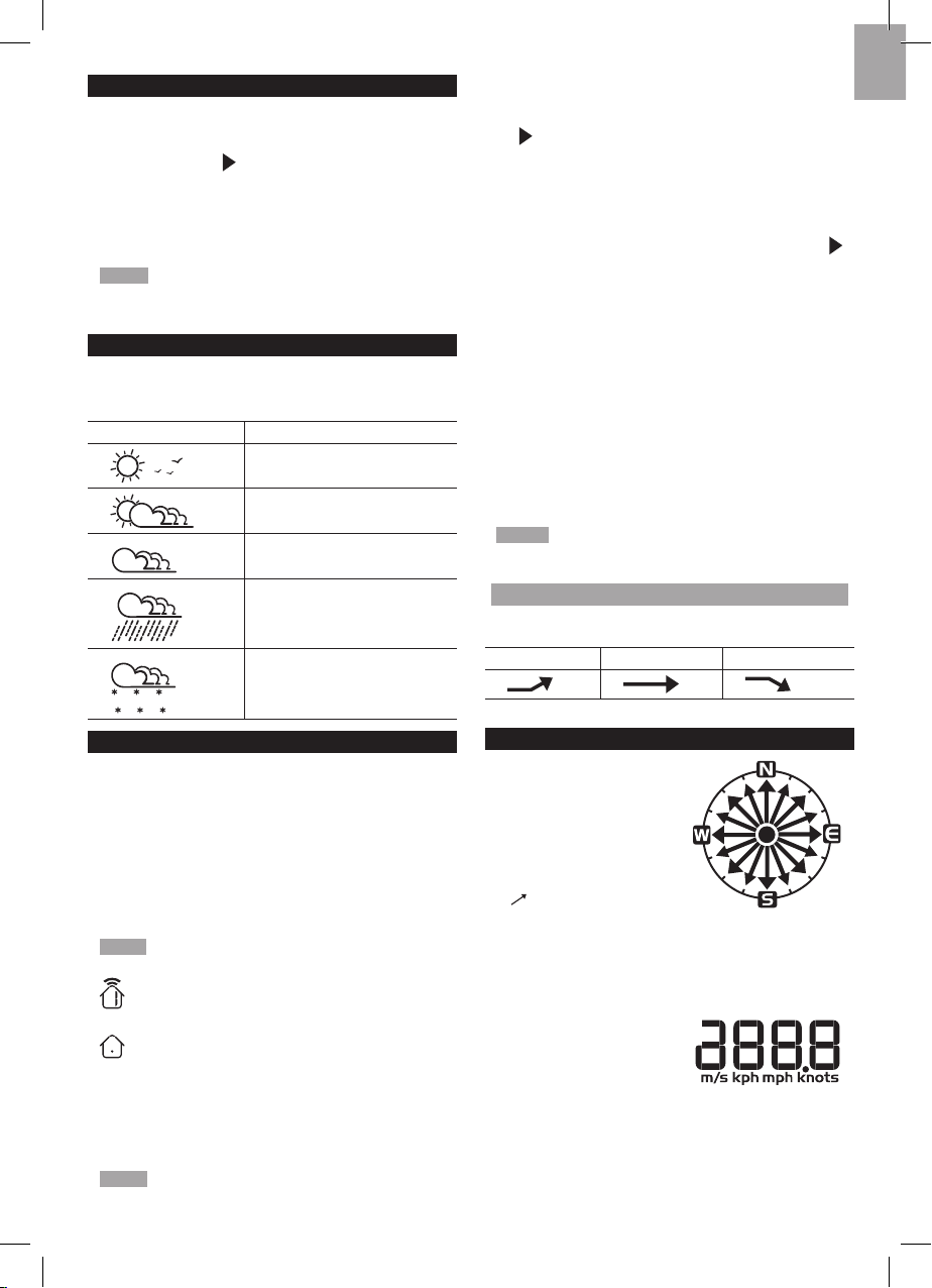
Weather Forecast Area
ICON DESCRIPTION
Sunny
Partly cloudy
Cloudy
Rainy
Snowy
TEMPERATURE AND HUMIDITY
The weather station displays indoor and outdoor
readings for:
1. Temperature / relative humidity (current / maximum
/ minimum)
2. Trend line
3. Wind chill (current / minimum) and dew point level
(current / maximum / minimum)
The wea the r station can con nec t up to 3 rem ote
sensors.
NOTE Channel 1 is dedicated for outdoor temperature
and humidity.
shows wh ich remote senso r’s dat a you ar e
viewing.
appears when indoor data is displayed.
The timestamp records the date and time when storing the
temperature and humidity readings in memory.
To select the temperature measurement unit:
Press UNIT to select °C / °F.
NOTE The unit of all temperature related displays will
be changed simultaneously.
To view temperature (Current / Max / Min temperature)
readings:
1. Press SELECT to navigate to the Temperature Area.
will show next to the Area.
2. Press
UP / DOWN to select the channel.
3. Press
MAX / MIN to toggle between current / MAX /
MIN displays.
To view humidity (Humidity, Dew point) readings
:
1. Press
SELECT to navigate to the Humidity Area.
will show next to the Area.
2. Press
UP / DOWN to select the channel.
3. Press MODE repeatedly to toggle betwe en the
humidity / dewpoint displays.
4. Press
MAX / MIN to toggle between current / MAX /
MIN displays.
The timestamp is displayed accordingly in the Clock
Area.
To clear the mem ori es and timestamp fo r the
temperature, humidity and dew point readings:
In the Temperature or Humidity Area, press and hold MAX
/ MIN to clear the readings.
NOTE The dew point advises at what temperature
condensation will form.
TEMPERATURE AND HUMIDITY TREND
The trend lines are shown next to the temperature and
humidity readings. The trend is shown as follows:
RISING STEADY FALLING
WIND CHILL / DIRECTION / SPEED
The base station provides
wind speed and wind
direction information.
To read the wind direction
find the compass point the
is pointing to.
The timestamp records the date and time when storing
the wind speed readings.
To select the wind speed unit:
Press UNIT to switch between:
• Metres per second (m/s)
• Kilometers per hour (kph)
• Miles per hour (mph)
• Knots (knots)
Page 8
8
EN
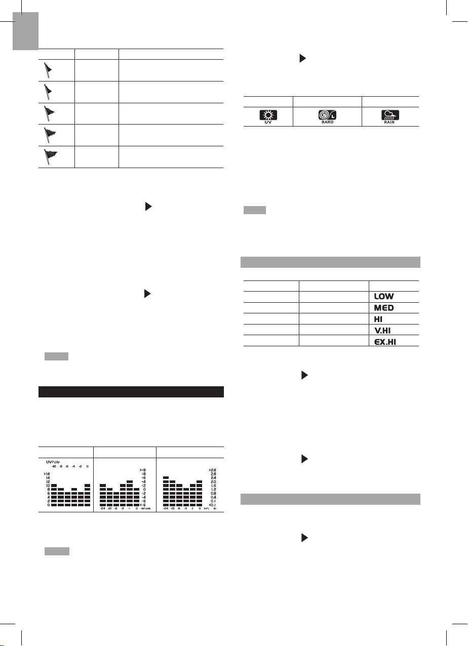
The wind level is shown by a series of icons:
ICON LEVEL DESCRIPTION
N/A <2 miles/h (<4km/h)
Light 2-8 miles/h (3-13 km/h)
Moderate 9-25 miles/h (14-41 km/h)
Strong 26-54 miles/h (42-87 km/h)
Storm >55 miles/h (>88 km/h)
To view the maximum wind speed and minimum wind
chill readings:
1. Press SELECT to navigate to the Wind Speed / Wind
Direction / Wind Chill Area.
will show next to the
Area.
2. Press
MAX / MIN to toggle between current / MAX
wind speed and current / MIN wind chill displays.
The timest amp of when maximum wind speed was
recorded is displayed accordingly in the Clock Area.
To clear minimum wind chill reading / maximum wind
speed reading:
1. Press SELECT to navigate to the Wind Speed / Wind
Direction / Wind Chill Area.
will show next to the
Area.
2. Press MAX / MIN repeatedly until minimum wind
chill reading or maximum wind speed reading is
displayed.
3. Press and hold MAX / MIN to clear the readings.
NOTE The wind chill factor is based on the combined
effects of temperature and wind speed. Displayed wind
chill is calculated solely from Channel 1 sensor.
UVI / BAROMETER / RAINFALL
The weather station works with one UV sensor and
one rain gauge. The station is capable of storing and
displaying the hourly history data for the last 10 hours
of UV index, and 24
hours of rainfall and barometric
pressure readings.
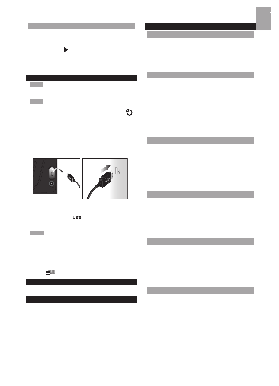
UVI BAROMETER RAINFALL
The bar chart display shows the current and historical
data for the UV index, barometric pressure and rainfall
readings.
NOTE The number shown in the horizontal axis (Hr)
indicates how long ago each measurement was taken (e.g.
3 hours ago, 6 hours ago, etc.). The bar represents the
measurement taken for that specific 1 hour period. E.g., if it
is 10:30 pm now, the bar plotted directly above -1 shows the
reading recorded from 9 to 10 pm and -6 shows the reading
recorded earlier in the evening, between 4pm-5pm.
To view the UV / Barometer / Rainfall readings:
1. Press
SELECT to navigate to the UV / Barometer /
Rainfall Area. will show next to the Area.
2. Press MODE to toggle between UVI / Barometer
/ Rainfal l readings. The correspondin g icon will
appear:
UVI BAROMETER RAINFALL
To select the measurement unit for the barometer or
rainfall readings:
In the UV / Barometer / Rainfall Area, press UNIT to
switch between:
• Barometer: Millimeters of mercury (mmHg), inches
of mercury (inHg), millibars per hectopascal (mb).
• Rainfall: Millimeters (mm), inches (in), recorded for
that hour.
NOTE As the purpose of the bar graph is only to provide
a quick comparison between the records of the past 24
hours, the vertical axis cannot convert from inches to mm.
Therefore, changing the measurement unit will have no
effect on the bar graph display.
UV INDEX
The UV index levels are as follows:
UV INDEX DANGER LEVEL ICON
0-2 Low
3-5 Moderate
6-7 High
8-10 Very high
11 and above
Extremely high
To view the maximum UV reading:
1. Press
SELECT to navigate to the UVI / Barometer /
Rainfall Area. will show next to the Area.
2. Press
MODE repeatedly to select UV display.
3. Press
MAX / MIN to toggle between current / MAX
UV index display.
The timestamp of when maximum UV was recorded is
displayed accordingly in the Clock Area.
To clear maximum UV reading:
1. Press SELECT to navigate to the UVI / Barometer /
Rainfall Area. will show next to the Area.
2. Press MODE repeatedly to select UV display.
3. Press and hold MAX / MIN to clear the readings.
BAROMETER
To set the altitude level com pens ation for the
Barometer readings:
1. Press
SELECT to navigate to the UVI / Barometer /
Rainfall Area. will show next to the Area.
2. Press MOD E repe ate dly to select Bar ome tric
display.
3. Press and hold MODE to enter the altitude setting.
4. Press
UP / DOWN to increase / decrease the setting
value.
5. Press
MODE to confirm the setting.
Page 9
9
EN
RAINFALL
To view the recorded rainfall of the current hour or
last 24 hours:
1. Press SELECT to navigate to the UVI / Barometer /
Rainfall Area. will show next to the Area.
2. Press MODE repeatedly to select Rainfall display.
3. Press MAX / MIN repeatedly to toggle between
current hour or past 24 hour rainfall.
UPLOAD DATA TO PC SOFTWARE
NOTE The software must be downloaded and installed
bef ore data can be uplo aded (ref er to Insta llation
Guide).
NOTE The USB is only used for uploading data. It cannot
be used for charging battery power.
1. After successful installation, double click on
desktop shortcut.
2. Click Display in Oregon Scientific Weather Station
dialogue box.
3. You will be prompted to select model number. Please
select your model in the drop-down list and refer to
the image next to your selection to confirm it is the
correct model.
3
4. Plug one end of the USB cable into the base station’s
USB port and the other end into the PC’s USB port.
Main unit will show .
5. Uploading will start immediately.
NOTE This product should be supplied by an identical
USB port complying with the requirements of Limited
Power Source.
To learn more about how to utilize the functions available
on the software, please refer to PC Software Manual,
downloadable from:
http://www2.os-weather.com/help/
Click on PC Software Manual.
BACKLIGHT
Press LIGHT to activate the backlight for 5 seconds.
RESET
Press RESET to return to the default settings.
SPECIFICATIONS
BASE STATION
Dimensions
(L x W x H)
180mm x 110mm x 47mm
(7.1 x 4.3 x 1.9 inches)
Weight
286g (10 ounces) without
battery
Battery 6V adaptor; 4 x UM-3 (AA) 1.5V
INDOOR BAROMETER
Barometer unit mb, inHg and mmHg
Measuring range 700 – 1050mb/hPa
Accuracy +/- 10 mb/hPa
Altitude setting Sea level
User setting for compensation
Weather display Sunny, Partly Cloudy, Cloudy,
Rainy and Snowy
Memory Historical data and bar chart for
last 24hrs
INDOOR TEMPERATURE
Temp. unit °C / °F
Displayed range 0°C to 50°C (32°F to 122°F)
Operating range -30°C to 60°C (-4°F to 140°F)
Accuracy 0°C - 40°C: +/- 1°C (+/- 2.0°F)
40°C - 50°C: +/- 2°C (+/- 4.0°F)
Memory Current, Min and Max temp.
Dew Point w/ Min and Max
INDOOR RELATIVE HUMIDITY
Displayed range 2% to 98%
Operating range 25% to 90%
Accuracy 25% - 40%: +/- 7%
40% - 80%: +/- 5%
80% - 90%: +/- 7%
Memory Current, Min and Max
RADIO-CONTROLLED / ATOMIC CLOCK
Synchronization Auto or disabled
Clock display HH:MM:SS
Hour format 12hr AM/PM or 24hr
Calendar DD/MM or MM/DD
Weekday in 6
languages
(E, D, F, I, S, R)
REMOTE WIND SENSOR UNIT
Dimensions
(L x W x H)
178 x 76 x 214 mm
(7 x 3 x 8.4 inches)
Weight
100 g (3.53 ounces) without
battery
Wind speed unit m/s, kph, mph, knots
Speed accuracy 2 m/s ~ 10 m/s (+/- 3 m/s)
10 m/s ~ 56 m/s (+/- 10%)
Direction accuracy 16 positions
Transmission of
wind speed signal
Approx. every 56 seconds
Page 10
10
EN
Memory Max wind speed
Battery 2 x UM-3 (AA) 1.5V batteries
OUTDOOR TEMPERATURE / HUMIDITY UNIT
Dimensions
(L x W x H)
92 x 60 x 20 mm
(3.6 x 2.4 x 0.79 in)
Weight
62 g (2.22oz) without battery
Humidity range 5% to 95%
Humidity accuracy 25% - 40%: +/- 7%
40% - 80%: +/- 5%
80% - 90%: +/- 7%
Temp. unit
°C / °F
Temperature
outdoor range
-30°C to 60°C (-22°F to 140°F)
Temperature
accuracy
-20°C to 0°C:
+/- 2.0°C (+/- 4.0°F)
0°C to 40°C:
+/- 1.0°C (+/- 2.0°F)
40°C to 50°C:
+/- 2.0°C (+/- 4.0°F)
50°C to 60°C:
+/- 3.0°C (+/- 6.0°F)
RF frequency 433 MHz
Range Up to 100 meters (328 feet)
with no obstructions
Transmission
Approx. every 102 seconds
Channel no. 3
Batteries 2 x UM-4 (AAA) 1.5V
REMOTE RAIN GAUGE
Dimensions
(L x W x H)
114 x 114 x 145 mm
(4.5 x 4.5 x 5.7 inches)
Weight
241 g (8.5 oz) without battery
Rainfall unit Mm and in
Range 0 mm – 9999 mm
Accuracy < 15 mm: +/- 1 mm
15 mm to 9999 mm: +/- 7%
Memory Past 24hrs, hourly from last
memory reset
Battery 2 x UM-3 (AA) 1.5V
PRECAUTIONS
• Do not subject the unit to excessive force, shock,
dust, temperature or humidity.
• Do not cover the ventilation holes with any items such
as newspapers, curtains etc.
• Do not immerse the unit in water. If you spill liquid
over it, dry it immediately with a soft, lint-free cloth.
• Do not clean the unit with abrasive or corrosive
materials.
• Do not tamper with the unit’s internal components.
This invalidates the warranty.
• Only use fresh batteries. Do not mix new and old
batteries.
• Images shown in this manual may differ from the
actual display.
• When disposing of this product, ensure it is collected
separately for special treatment and not as household
waste.
• Placement of this product on certain types of wood
may result in damage to its finish for which Oregon
Scientific will not be responsible. Consult the furniture
manufacturer's care instructions for information.
• The contents of this manual may not be reproduced
without the permission of the manufacturer.
• Do not dispose old batteries as unsorted municipal
waste. Collection of such waste separately for special
treatment is necessary.
• Please note that some units are equipped with a
battery safety strip. Remove the strip from the battery
compartment before first use.
NOTE The technical specifications for this product and
the contents of the user manual are subject to change
without notice.
NOTE Features and accessories will not be available
in all countries. For more information, please contact
your local retailer.
ABOUT OREGON SCIENTIFIC
Visit our website (www.oregonscientific.com) to learn
more about Oregon Scientific products.
If you ’re in the US and wou ld like to contact our
Customer Care department directly, please visit: www2.
oregonscientific.com/service/support.asp
Fo r in te rnati on al in qu iries , pl ea se vi si t: ww w2.
oregonscientific.com/about/international.asp
EU DECLARATION OF CONFORMITY
Hereby, Oregon Scientific, declares that this Wireless
Pro Weather Station with USB upload (Model: WMR88 /
WMR88A) is in compliance with the essential requirements
and other relevant provisions of Directive 1999/5/EC. A
copy of the signed and dated Declaration of Conformity is
available on request via our Oregon Scientific Customer
Service.
COUNTRIES RTTE APPROVAL COMPLIED
All EU countries, Switzerland CH
und Norwegen N
 Loading...