

Oregon Scientific Chain Saw Maintenance Manual
Maintenance &
Safety Manual
www.oregonchain.eu
Advanced Cutting Technology

Introduction
Your chainsaw is only as good as your chain, guide bar, and sprocket.
They function as a team while doing the actual work of cutting wood and,
therefore, must be maintained as a team.
A properly maintained chain, bar, and sprocket will provide excellent
cutting performance. An improperly maintained chain will cause
damage to the bar and sprocket, will cut poorly, and will create potential
Introduction
safety hazards.
®
This manual addresses the maintenance of only OREGON
chains, bars, and sprockets. For information on maintenance and
operation of your saw, refer to your saw’s operator’s manual or contact
your local chainsaw dealer.
manufactured
2.
Introduction
CHAINSAW SAFETY
IMPORTANT SAFETY MESSAGE
SAFETY SYMBOL
This safety symbol is used to highlight safety messages. When you see
this symbol, read and follow the safety message to avoid severe personal
injury.
WARNING
All cutting chain can kick back, which can lead to dangerous loss of
control of the chainsaw and result in serious injury to the saw operator or
by standers. Follow all instructions in your chainsaw operator’s manual
and in this booklet for proper use and maintenance of your saw’s cutting
chain, guide bar, and sprocket.
GUARD AGAINST CHAINSAW KICKBACK
• Know your personal level of chainsaw experience.
• Know your cutting chain.
Introduction
If you do not have experience and specialized training for dealing with
chainsaw kickback, then OREGON
®
urges you to use only low-kickback
saw chains.
WHAT IS KICKBACK?
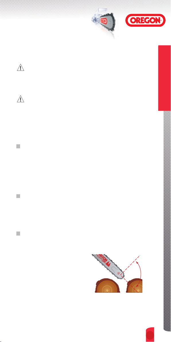
Kickback is the violent backward and/or upward motion of the chainsaw
guide bar occurring when the chain near the nose or tip of the guide bar
contacts any object, such as another log or branch, or when the wood
closes in and pinches the saw chain in the cut.
TO HELP AVOID INJURY
Kickback Awareness
➊
Be alert at all times to guard against a possible kickback reaction. Always
be aware of the position of your
bar’s nose.
➋
Different models of cutting
chain are available for most
cutting tasks. Use the
chain, suitable for your
type of cutting, with the
lowest kickback potential.
➌
Narrow-nose bars such as OREGON® Double Guard™ bars are
Potential Kickback Situation
recommended for maximum kickback safety.
3.
Introduction
CHAINSAW SAFETY
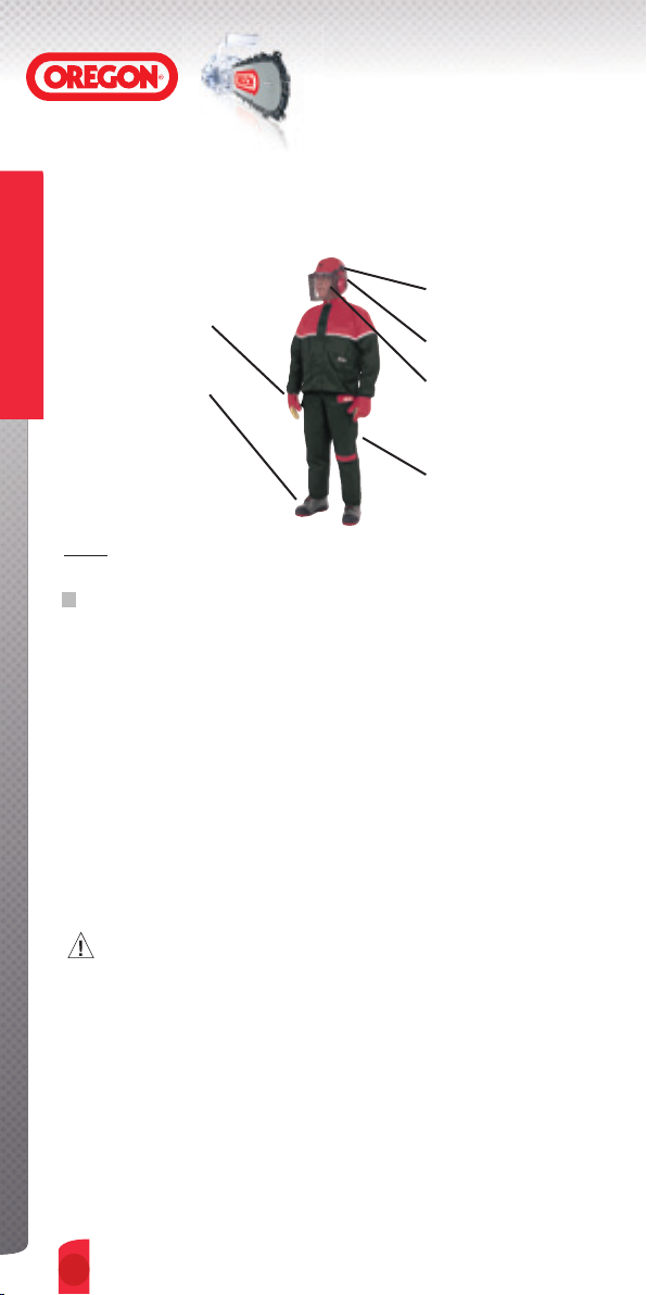
CLOTHING AND PROTECTIVE EQUIPMENT
Wear hard hat to protect
Wear protective gloves to
prevent slippage and to
protect hands.
Introduction
Wear chainsaw protective
boots or safety boots and
gaiters to protect feet.
NOTE: Dress properly - do not wear clothing that is too tight or too loose.
MAKE PROPER WORK PRACTICES A HABIT
• Use only a right-hand grip to hold your saw (right hand on the trigger,
left hand on the front handle).
• Keep your left arm straight for better control.
• Hold saw firmly with both hands. Keep thumb firmly locked around
front handle.
• Stand to the side of the chainsaw, never behind it.
• Run engine at full throttle.
• Use low-kickback saw chain and a reduced-kickback guide bar.
• Keep the chainsaw, cutting chain, guide bar and sprocket properly
maintained.
• Stand with feet well braced and your body balanced.
• Cut only wood with your chainsaw. Do not cut any other material.
head.
Wear ear protection to
protect ears.
Wear safety goggles or
face shield to protect eyes.
Wear protective trousers
or leggings to protect legs
CAUTION
▲
Keep yourself clear of the work. Before cutting :
• Calculate how the object being cut will fall.
• Determine if the saw may be thrown unexpectedly by the movement
of the cut material.
• Position yourself to avoid injury.
▲
Never cut above shoulder level.
▲
Never cut while in a tree, or while on a ladder.
▲
Keep others away from the cutting area.
Do not allow others to hold wood during cutting.
4.

Contents
INTRODUCTION
Introduction .............................
Chainsaw safety ......................
CHAIN
Chain Terms ..........................
Chain Pitch ...........................
Chain Gauge ........................
Parts of a Cutter .....................
Cutter Sequence ....................
Parts of a Saw Chain .............
Maintenance Terms ................
Chain maintenance tools ........
Chain identification chart .....
2
2
2
2
2
3
3
4
5-7
Chain drive-link number
identification .........................
Chain letter identification ........
Four basic rules ..............
How to maintain the chain .....
How to tension chain ......
How to lubricate chain ..........
8
9
10-11
12
13-15
15
How to set depth
gauges ..........................
How to sharpen cutters ....
How to install chain parts
How to break out rivets ...
How to run-in a new chain .....
End-user symbols ...................
Filing specifications ........
Chain troubleshooting .....
16-17
18-19
20-21
22-23
24
25
26-47
48-54
GUIDE BARS
Guide bar terms ...................
55
Guide bar maintenance
tools ....................................
Guide bar maintenance ...
How to replace
Power Match
®
noses .......
55
56-57
58-59
Pro-Lite® noses
sprockets ........................
60-61
Guide bar
troubleshooting ...............
62-64
DRIVE SPROCKETS
Sprocket terms, tools,
and installation .....................
Sprocket maintenance .....
65
66-67
Sprocket
troubleshooting ...............
68-69
USEFUL INFORMATION
Useful information ...........
70-71
Contents
CONTENTS
1.
Saw Chains
OREGON® CHAIN TERMS
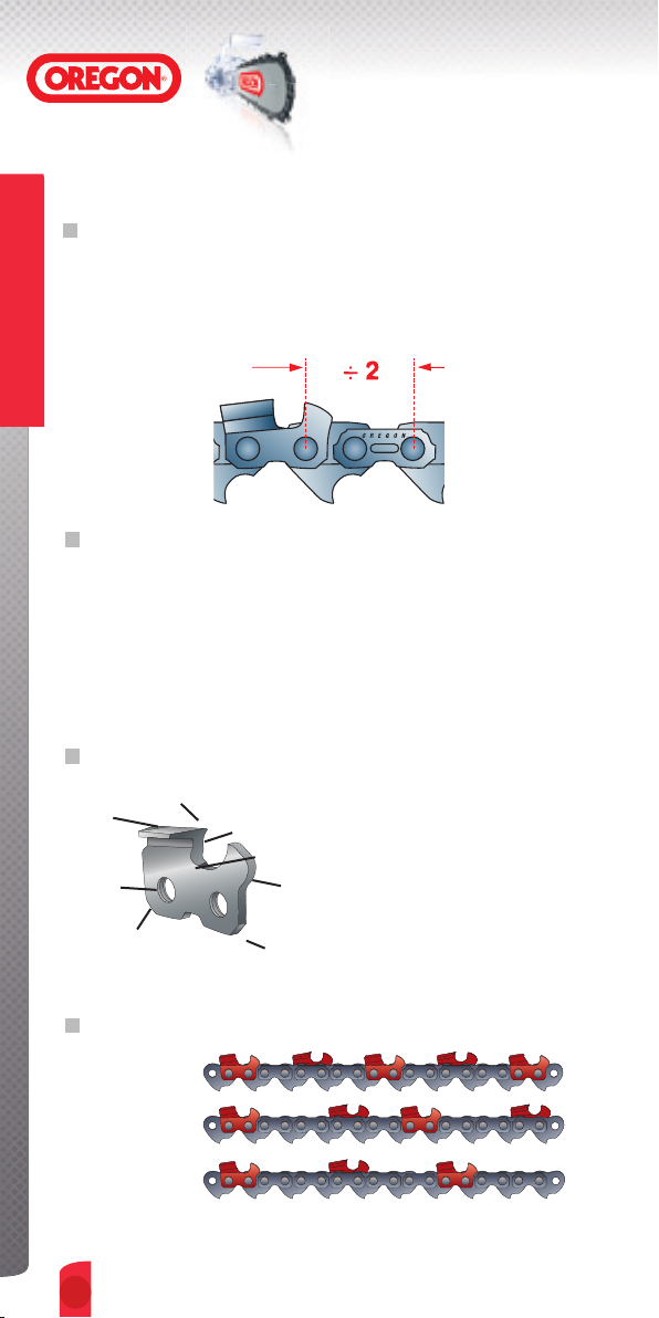
CHAIN PITCH
Chain Pitch is the distance between any three consecutive rivets, divided
by two. OREGON
1/4", .325", 3/8", .404" and 3/4".
Saw Chains
CHAIN GAUGE
Chain gauge is the drive link’s thickness where it fits into the guide-bar
groove. The industry standard for chain gauges are:
.043" (1.1mm), .050" (1.3mm), .058" (1.5mm), .063" (1.6mm)
OREGON
for Harvester applications.
®
chain pitches are:
®
chain gauges of .080" (2mm) and .122" (3.1mm) are used
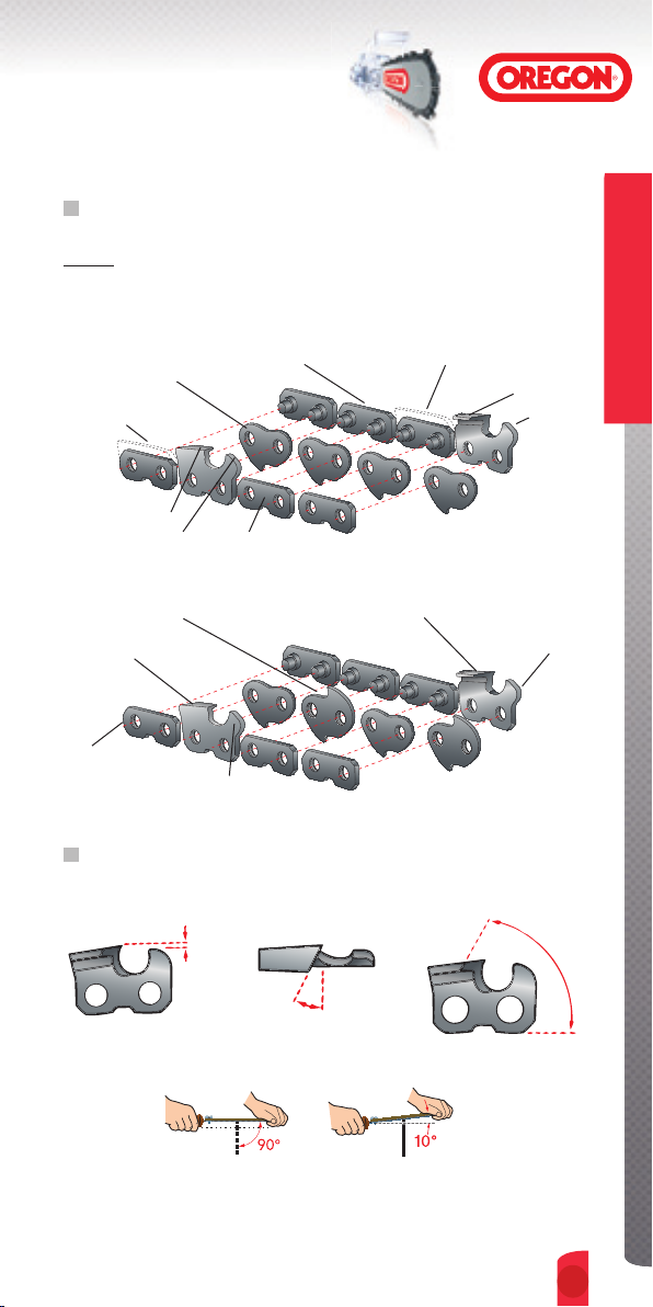
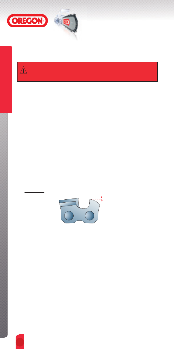
THE PARTS OF A CUTTER
Top
plate
Rivet
Hole
Cutting corner
Side Plate
Gullet
Heel
CHAIN CUTTER-SEQUENCE TERMS
Standard
Semi-Skip
Skip
Introduction
IntroductionIntroduction
2.
2.
Toe
Depth
Gauge
Saw Chains
OREGON® CHAIN TERMS
THE PARTS OF A SAW CHAIN
NOTE: Highlighted parts below indicate kickback-reducing “bumper
link" features: bumper tie strap, bumper drive link, and ramped depth
gauge.
Drive Link
Bumper Tie Strap
Right-hand Cutter
Ramped Depth Gauge
Bumper Drive Link
Right-hand Cutter
Tie Strap
Depth Gauge
Preset Tie Strap
Tie Strap
Preset Bumper Tie Strap
Left-hand Cutter
Left-hand Cutter
Depth Gauge
CUTTER MAINTENANCE TERMS
Depth-gauge Setting Top-plate Filing Angle Top-plate Cutting Angle
Ramped
Depth
Gauge
Saw Chains
File-guide Angle
3.
Saw Chains
OREGON® CHAIN-MAINTENANCE TOOLS
FILING TOOLS
ASSEMBLED FILE GUIDE
➊
Saw Chains
ROUND FILE
➌
BAR-MOUNTED
➏
FILING GUIDE
GRINDERS
SURE SHARP®
➊
12-VOLT GRINDER
FLAT FILE
➍
FILE HANDLE
➐
BENCH-MODEL
➋
CHAIN GRINDER
SHARPENING KIT
➋
DEPTH-GAUGE TOOL
➎
FILING VISE
➑
MINI GRINDER
➌
GRINDING WHEELS
➍
CHAIN-REPAIR TOOLS
CHAIN BREAKER
➊
Introduction
IntroductionIntroduction
4.
4.
RIVET SPINNER
➋
POCKET-CHAIN
➌
BREAKER
Saw Chains
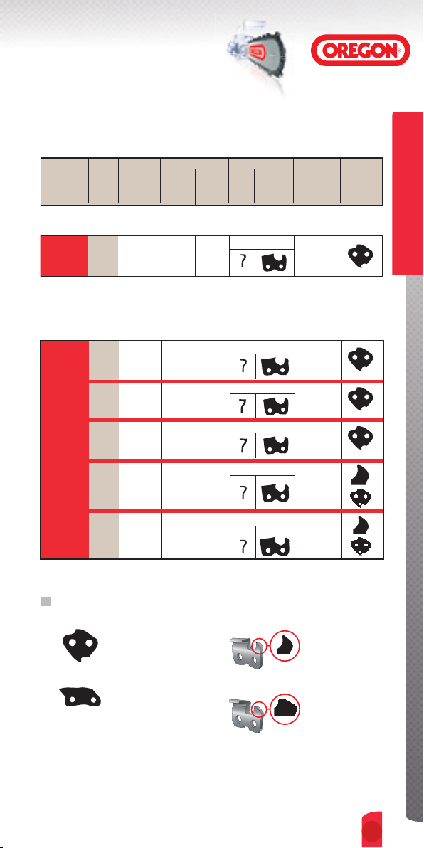
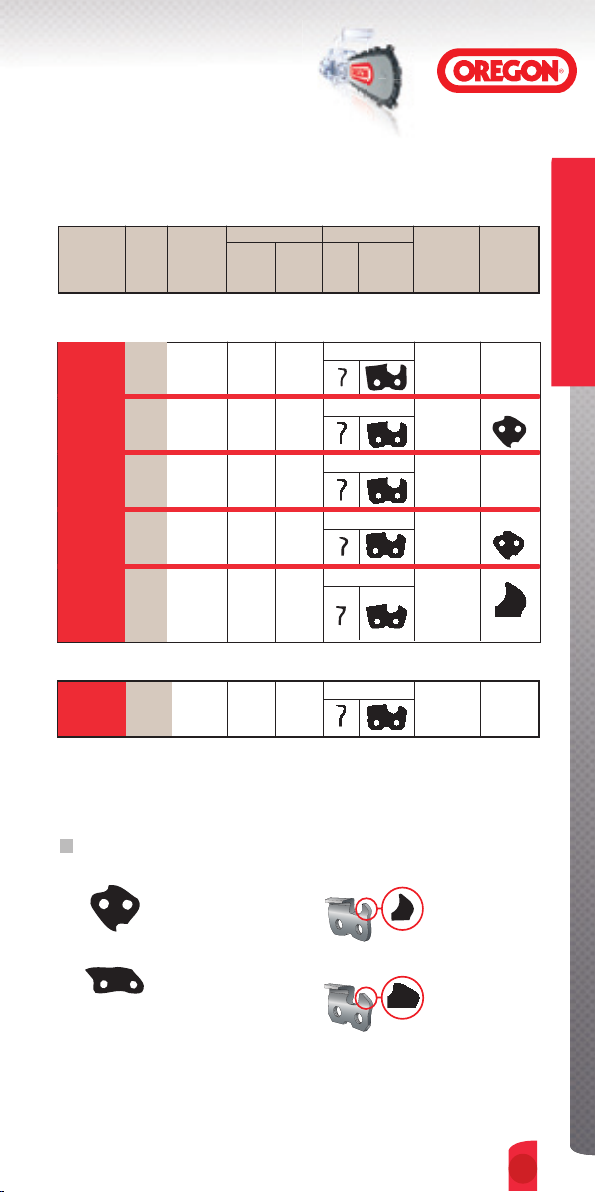
CHAIN IDENTIFICATION
OREGON® FILING OREGON® CHAIN GAUGE CUTTER TYPE CUTTER KICKBACK
CHAIN SPEC’S CHAIN IN. MM END SIDE SEQUENCE REDUCING
PART TYPE VIEW VIEW FEATURES
(IF ANY)*
1/4" PITCH CHAIN
25AP
26
MICRO
CHISEL
050"
®
1.3
Page
.325" PITCH CHAINS
050"
20BPX
21BPX
22BPX
20LPX
21LPX
22LPX
M21LPX
M22LPX
95VPX
95R
Page
27
Page
28
Page
31
Page
30
Page
43
MICRO
CHISEL
SUPER
20
MULTICUT
MICRO-
LITE™
RIPPING
CHAIN
®
058"
063"
050"
058"
063"
058"
063"
050"
050"
1.3
1.5
1.6
1.3
1.5
1.6
1.5
1.6
1.3
1.3
KICKBACK REDUCING FEATURES
➊
DRIVE LINK
BUMPER
CHISEL
CHISEL
®
STANDARD
®
STANDARD
STANDARD
STANDARD
®
STANDARD
®
STANDARD
RAMPED
MICRO CHISEL
MICRO CHISEL
MICRO CHISEL
MICRO CHISEL
➌
DEPTH GAUGE
Saw Chains
➋
TIE STRAP
BUMPER
➍
RAMPED
DEPTH GAUGE
LOW-PROFILE
5.
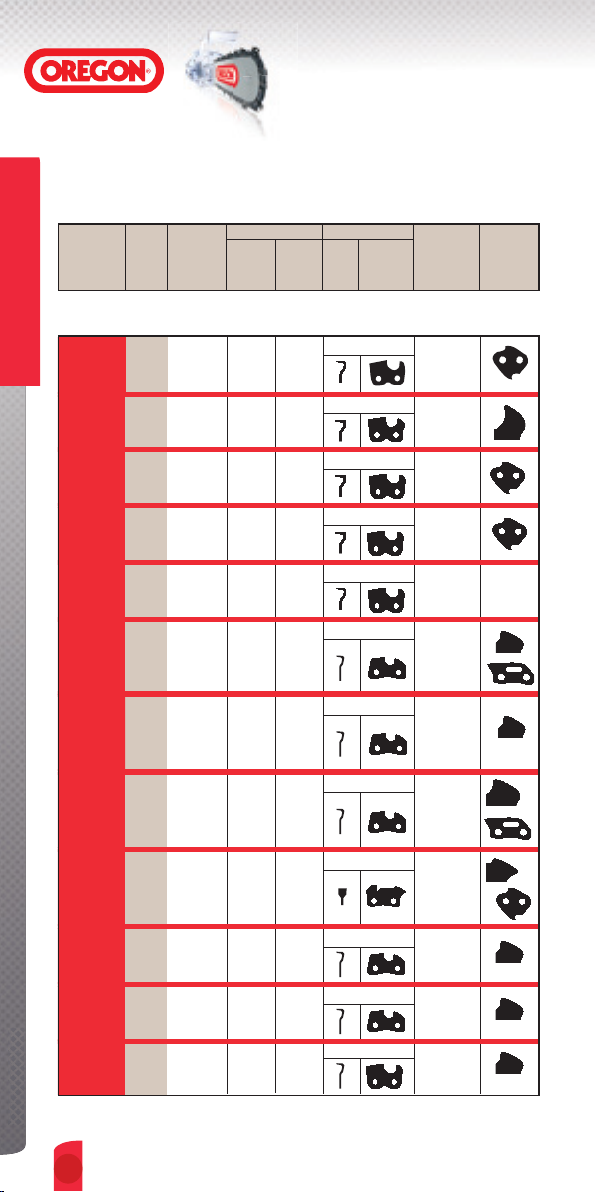
Saw Chains
CHAIN IDENTIFICATION
OREGON® FILING OREGON® CHAIN GAUGE CUTTER TYPE CUTTER KICKBACK
CHAIN SPEC’S CHAIN IN. MM END SIDE SEQUENCE REDUCING
PART TYPE VIEW VIEW FEATURES
(IF ANY)*
3/8" PITCH CHAINS
Saw Chains
72DX/DPX
73DX/DPX
75DX/DPX
72LGX
73LGX
75LGX
72LPX
73LPX
75LPX
M73LPX
M75LPX
72RD
73RD
75RD
90SG
91VX
91VG
91LX
Page
33
Page
34
Page
35
Page
32
Page
36
Page
38
Page
39
Page
40
-
S-70
SUPER
GUARD
SUPER 70
Low
vibration
MULTICUT
RIPPING
CHAIN
MICRO-
LITE™
Low
vibration
Low
vibration
Low
profile
Low
vibration
XTRA
GUARD
POWER
SHARP
050"
058"
063"
050"
058"
™
063"
050"
058"
063"
058"
063"
050"
058"
063"
043"
050"
050"
™
050"
®
SEMI-CHISEL
1.3
1.5
1.6
1.3
1.5
1.6
1.3
1.5
1.6
1.5
1.6
1.3
1.5
1.6
1.1
1.3
1.3
1.3
CHISEL
CHISEL
CHISEL
SEMI-CHISEL STANDARD
CHAMFER-CHISEL
CHAMFER-CHISEL
CHAMFER-CHISEL
SPECIALIZED
STANDARD
(LG)
STANDARD
(LP)
STANDARD
STANDARD
(SG)
STANDARD
STANDARD
STANDARD
STANDARD
91R
M91VX
91VXL
Introduction
IntroductionIntroduction
6.
6.
Page
37
Page
39
Page
29
RIPPING
CHAIN
MULTICUT
SEMI-
CHISEL
050"
050"
050"
CHAMFER-CHISEL
1.3
CHAMFER-CHISEL
1.3
1.3
SEMI-CHISEL
STANDARD
STANDARD
STANDARD
Saw Chains
CHAIN IDENTIFICATION
OREGON® FILING OREGON® CHAIN GAUGE CUTTER TYPE CUTTER KICKBACK
CHAIN SPEC’S CHAIN IN. MM END SIDE SEQUENCE REDUCING
PART TYPE VIEW VIEW FEATURES
(IF ANY)*
.404" PITCH CHAINS
16H
18HX
26
27, 27P
27R
59AC
58L
59L
Page
47
Page
41
Page
42
Page
44
Page
45
HARVESTER
MICRO-
CHISEL
RIPPING
MICROBIT
GUARD
CHAIN
SUPER
063"
080"
058"
®
063"
063" 1.6
®
063"
058"
063"
™
1.6
2.0
1.5
1.6
1.6
1.5
1.6
3/4" PITCH CHAINS
Page
SEMI-
122"
11H
46
CHISEL
3.1
KICKBACK REDUCING FEATURES
➊
DRIVE LINK
BUMPER
MICRO CHISEL
MICRO CHISEL
MICRO CHISEL
➌
DEPTH GAUGE
®
STANDARD
®
STANDARD
®
(R)
STANDARD
CHIPPER STANDARD
CHISEL
SEMI-CHISEL
STANDARD
STANDARD
RAMPED
P ONLY
CP ONLY
Saw Chains
➋
TIE STRAP
BUMPER
➍
RAMPED
DEPTH GAUGE
LOW-PROFILE
7.
Saw Chains
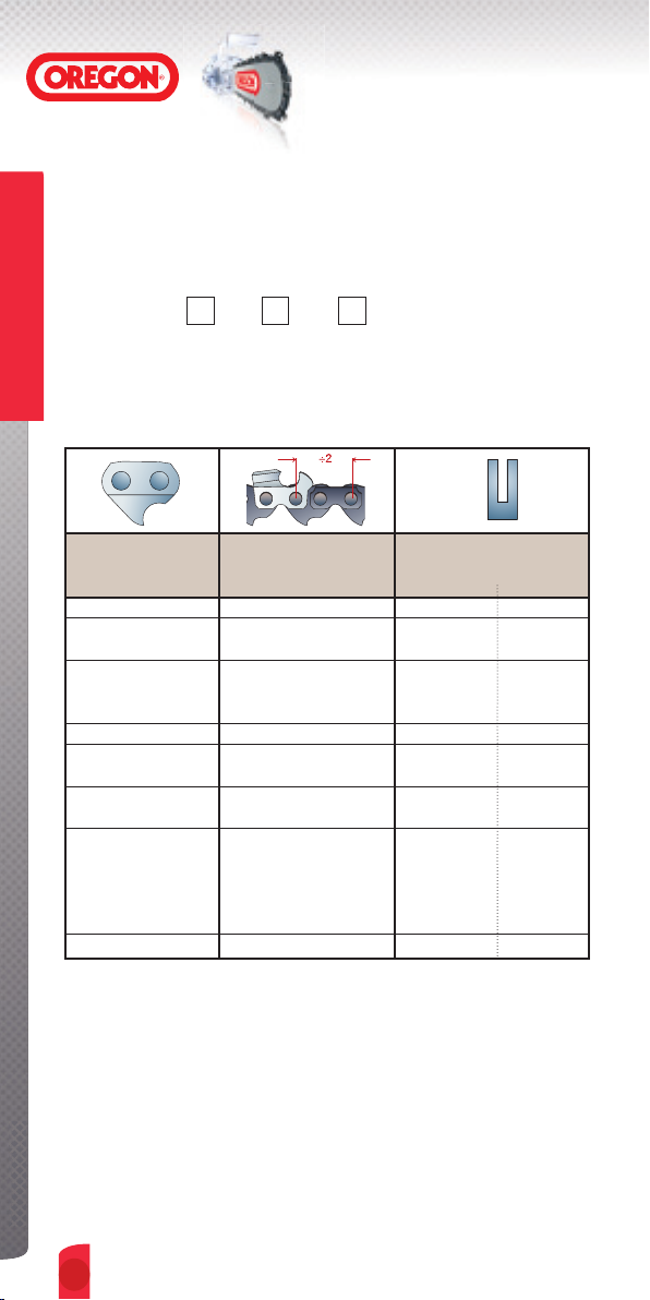
CHAIN DRIVE-LINK NUMBER IDENTIFICATION
Nearly all OREGON® chains are named by a part number made up of a
number (see below), followed by one or two letters (see page 9).
OREGON
The Numbers: 18 HX, 72 LPX, 91 VG
The numbers are stamped on the chain’s drive links and indicate the
Saw Chains
physical size of the chain (pitch and gauge).
®
Part-number Examples: 18 HX, 72LPX, 91VG
CHAIN
NUMBER
11 3/4" .122" 3.1
16 .404" .063" 1.6
18 .404" .080" 2.0
20 .325" .050" 1.3
21 .325" .058" 1.5
22 .325" .063" 1.6
25 1/4" .050" 1.3
26 .404" .058" 1.5
27 .404" .063" 1.6
58 .404" .058" 1.5
59 .404" .063" 1.6
72 3/8" .050" 1.3
73 3/8" .058" 1.5
75 3/8" .063" 1.6
90 3/8" .043" 1.1
91 3/8" .050" 1.3
95 .325" .050" 1.3
GAUGE
PITCH
MM
IN
Introduction
IntroductionIntroduction
8.
8.

Saw Chains
CHAIN LETTER IDENTIFICATION
The letters: 18 HX , 72 LPX , 91 VG
The letters represent cutter type and sequence, safety features, or other
physical traits of the chain.
AC Chipper Cutter,
Standard Sequence
AP Micro Chisel
®
Cutter,
Bumper Drive Link,
Standard Sequence
BC Chipper cutter with standard
sequence (11BC only)
®
BPX Low vibration Micro Chisel
Cutter, Bumper Drive Link,
Standard Sequence
DX Semi-chisel Cutter, Standard
Sequence
DPX Semi-chisel Cutter, Bumper
Drive Link, Standard
Sequence
H Modified for Harvester
applications, Micro Chisel
®
or Semi-chisel cutters
with Standard Sequence
L Round-ground chisel cutters
with standard sequence (.404"
58L & 59L)
LGX Round-ground Chisel
Cutter, Ramped Depth
Gauge, Standard
Sequence.
LPX Low vibration Round-ground
Chisel Cutter, Bumper Drive
Link, Standard Sequence
®
LX Power Sharp
Chain,
Ramped Depth Gauge,
Bumper Drive Link,
Standard Sequence
(no hand maintenance
required)
M Specially built chain with
round-ground chisel cutters
(M73, 75LPX, M21,22LPX)
and Bumper Drive Link or
chamfer-chisel cutter (M91VX)
and ramped depth gauge for
effective cutting in extremely
dirty or abrasive conditions
R Ripping Chain, Chamfer-chisel
(91R) or Micro-chisel
(95R,27R) Cutter,
Standard Sequence
RA Ripping Chain, Micro-chisel
Cutter, Skip Sequence
RD Ripping chain with semi-
chisel cutters and standard
sequence
SG Low vibration chamfer-chisel
cutters, ramped depth gauge,
bumper tie strap, standard
sequence, narrow kerf design.
VG Low-vibration Chamfer-chisel
cutter, ramped depth gauge,
bumper tie strap, standard
sequence
VPX Low-vibration Micro Chisel™
cutter, ramped depth gauge,
bumper drive link, narrow-kerf
design (95VPX only)
VX Low-vibration Chamfer-chisel
cutters, ramped depth gauge,
standard sequence
VXL Low-vibration Semi-chisel
cutters with long top plate,
ramped depth gauge,
standard sequence
Saw Chains
9.
Saw Chains
THE FOUR BASIC SAW-CHAIN RULES
ATTENTION CHAINSAW USERS:
®
OREGON
rules. Users who know and follow these rules can count on superior
performance from their chain, bar, and sprocket, - and reduce safety
hazards at the same time.
Saw Chains
Your chain must be correctly tensioned.
More chain and bar problems are caused by incorrect chain tension
than by any other single factor. See pages13 and 14 on how to tension
your chain.
urges you to become familiar with the four basic saw-chain
RULE NUMBER 1
RULE NUMBER 2
Your chain must be well lubricated
A constant supply of oil to your saw’s bar, chain and sprocket is vital.
Without it, excessive friction, wear, and damage will occur.
See page 15 for instructions on how to lubricate your chain.
Introduction
IntroductionIntroduction
10.
10.
Saw Chains
THE FOUR BASIC SAW-CHAIN RULES
RULE NUMBER 3
Your chain’s depth gauges must be set correctly
Depth-gauge setting and depth-gauge shape are critical to performance
and safety. See pages 16-17 for instructions on how to set your chain’s
depth gauges.
Saw Chains
RULE NUMBER 4
Your chain must be sharp
When your chain is sharp, it does the work. When it’s not, you do the work
- and your cutting attachments will wear more rapidly. See pages 18 and 19
for instructions on how to sharpen your chain. See pages 26 to 47 to find
maintenance specifications for each OREGON
®
chain type.
11.
Saw Chains
HOW TO MAINTAIN CHAIN
ATTENTION: DEALERS, CHAINSAW USERS, AND ANYONE WHO
SERVICES SAW CHAIN - IMPORTANT SAFETY INFORMATION.
®
OREGON
Saw Chains
techniques, and the possible dangers which can result if chain is not
properly maintained.
Always turn off your saw’s engine before handling the chain,
urges you to become familiar with proper chain-maintenance
WARNING
Failure to follow the instructions below can result in severe
injury to the saw operator, bystanders, or the person
performing maintenance.
guide bar or sprocket.
Any one of the following conditions can increase a chain’s
potential kickback energy, increase the risk of a chain throwing
itself off the bar, or increase the risk of other hazards associated
with chainsaw use.
1. Incorrect sharpening of chain angles.
2. Dull chain.
3. Alteration of kickback-reducing chain features.
4. Excessive chain depth-gauge settings.
5. Incorrect chain depth-gauge shapes.
6. Loose chain tension.
7. Incorrectly installed chain parts.
8. Loose rivets, or cracks or breaks in any chain component.
When performing maintenance on saw chain, follow all instructions
on pages 12 through 54. Doing so can minimize the risk of injury.
Introduction
IntroductionIntroduction
12.
12.
Saw Chains
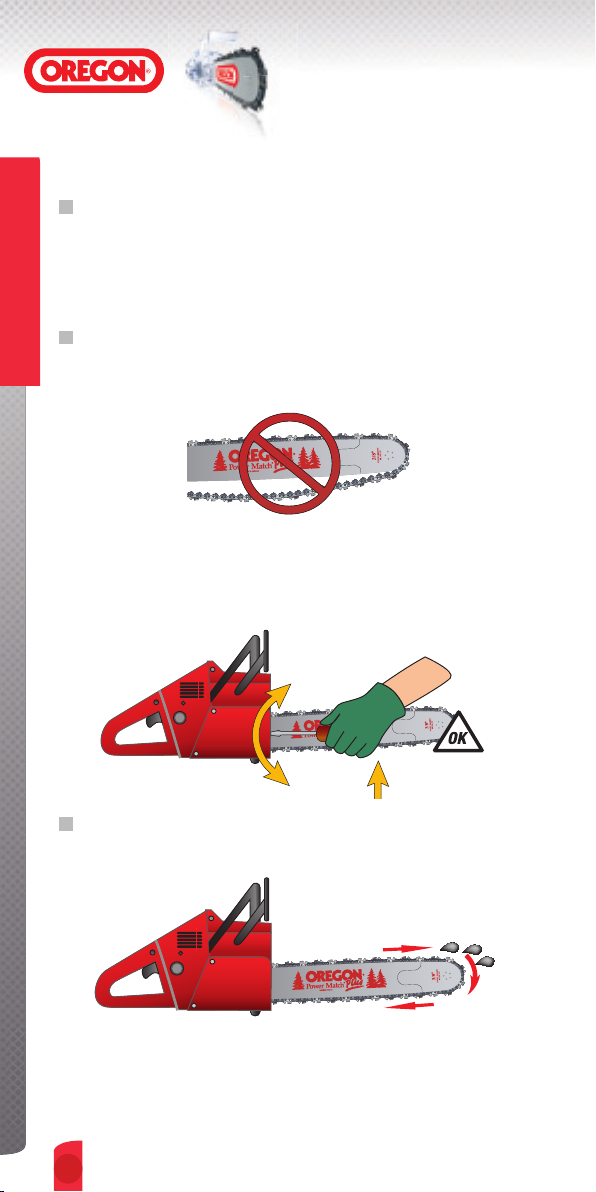
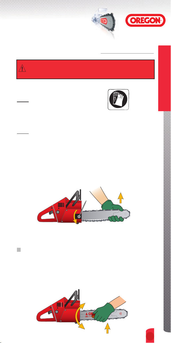
HOW TO TENSION YOUR CHAIN WITHOUT INTENZ™
Read the warnings on page 12.
NOTE: Always wear protective gloves.
➊
Turn the engine off.
NOTE: Never tension your chain right after cutting. Chain tensioned
while hot can cool and contract, causing tension to be much too tight.
Let chain cool first.
➋
Loosen bar-mounting nuts on the side of your saw.
➌
Pull the bar nose up, and keep it up as you adjust tension.
Saw Chains
➍
Adjust tension as follows:
If you have a solid-nose bar
Turn your saw’s tension-adjustment screw until the bottoms of the
➞
lowest tie straps and cutters come up and just touch the bottom of
the bar rail.
13.
Saw Chains
HOW TO TENSION YOUR CHAIN WITHOUT INTENZ™
If you have a sprocket-nose bar
Tension must be tighter than on a solid-nose bar. Turn your saw’s
➞
Saw Chains
tension-adjustment screw until the bottoms of the lowest tie straps
and cutters come up and solidly contact the bottom of the bar rail.
➎
With either type of bar, hold the nose up and tighten your saw’s rear
bar-mounting nut first, then tighten the front nut.
➏
Pull the chain by hand along the top of the bar several times,
from the engine to the bar’s tip. Chain should feel snug but still pull
freely.
NOTE: If you have a sprocket-nose bar you should now perform the snap
test. Grasp the chain along the bottom of the bar, pull down, and let go.
Chain should snap back to its original position, solidly contacting the
bottom of the bar.
➐
Check tension often during operation, especially during the first
half-hour. If chain loosens: stop, let chain cool, and readjust tension.
Introduction
IntroductionIntroduction
14.
14.
Saw Chains
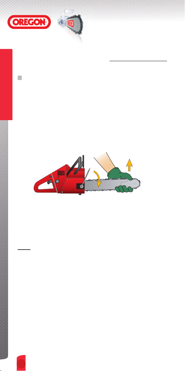
HOW TO TENSION YOUR CHAIN WITH INTENZ™
➊
Turn the engine off.
➋
Loosen the bar mounting
nuts on the side of the saw.
➌
Insert a combination tool blade in the Intenz™ slot of the guide bar.
➍
Turn the combination tool to move the guide bar forwards, away
from the saw as far as possible.
Saw Chains
➎
Tighten the back bar mounting nut, then tighten the front nut
HOW TO LUBRICATE YOUR CHAIN
➊
Keep your saw’s chain-oiling system filled with clean bar-and-chain
oil.
➋
Never put used oil, or old motor oil in your saw or on your chain.
➌
Be sure your chain, bar, and sprocket are always receiving oil from
the saw during operation.
➍
Fill your oil reservoir each time you fill your gas tank.
15.
Saw Chains
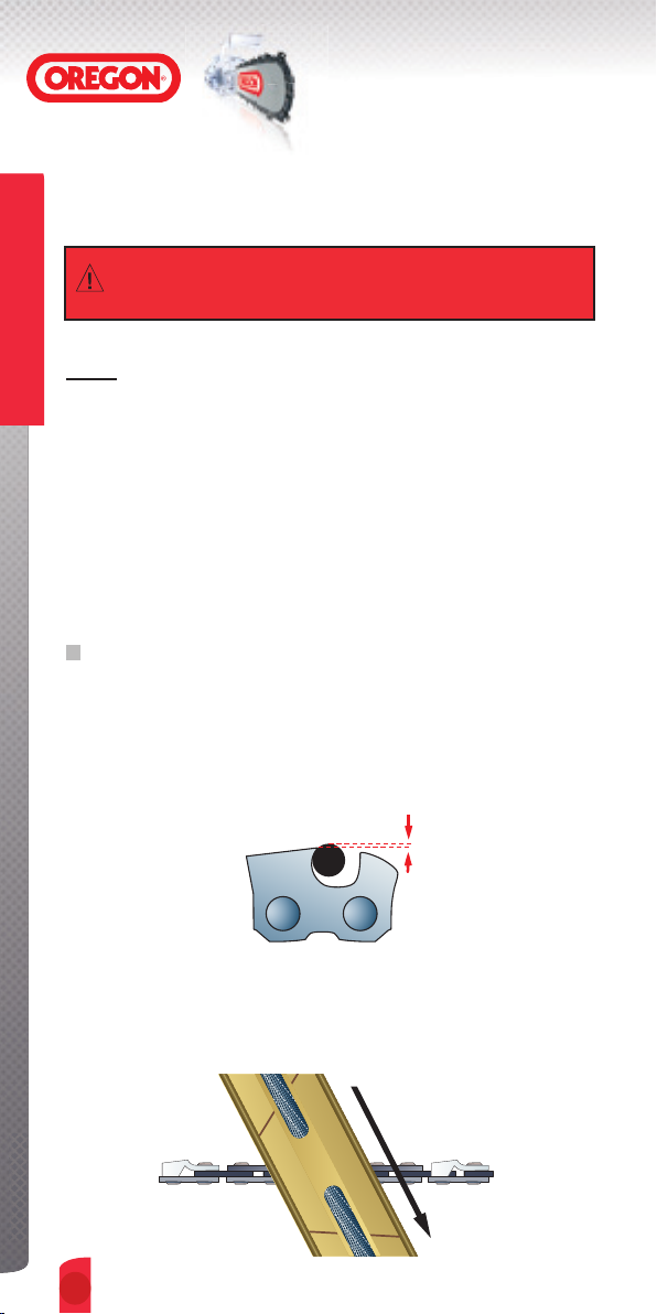
HOW TO SET DEPTH GAUGES
Read the warnings on page 12.
Saw Chains
NOTE:
• On saw depth-gauge setting requires proper chain tension, as shown
on pages 13-14,prior to filing.
• Pages 26 through 47 show the correct depth-gauge setting and the
part number of the correct depth-gauge tool for each of the different
OREGON
• Find the page (26-47), which gives the correct filing specifications
for your OREGON
chart on pages 5, 6 and 7.
• If unsure of your OREGON
OREGON
• Most OREGON
gauge indicating the correct depth-gauge setting.
EXAMPLE: .025" (0.64mm)
®
chain types.
®
chain type. To do so, use the Chain identification
®
®
saw chain dealer.
®
chains have a number stamped on each depth
chain’s type, or part number, ask your
.025" (0.64mm) Depth-gauge Setting
➊
Use a depth-gauge tool with the correct built-in setting for your
chain and check your depth gauges every 3 or 4 sharpenings.
➋
Place the tool on top of your chain so one depth gauge protrudes
through the slot in the tool.
➌
If the depth gauge extends above the slot, file the depth gauge
down level with the top of the tool using a flat file.
Never file the depth gauge down enough to exceed the depth-gauge
setting specified in this manual for your OREGON
Introduction
IntroductionIntroduction
16.
16.
®
chain.
Saw Chains
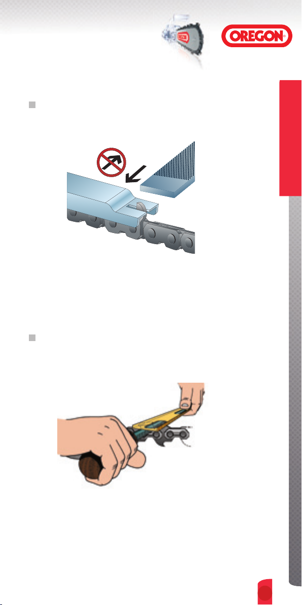
HOW TO SET DEPTH GAUGES
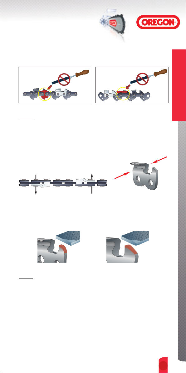
NOTE: Do not file or alter the tops of kickback-reducing bumper tie
straps or bumper drive links.
➍
File from the inside of the cutter to the outside
outside
inside
➎
After lowering, always file off the front corner of each depth gauge
parallel to its original rounded or ramped shape.
Saw Chains
NOTE: On many chains, it may be helpful to tip the depth gauge tool on
end and place it in front of the working corner in order to protect
the cutting surfaces when re-shaping depth gauges.
17.
Saw Chains
HOW TO SHARPEN CUTTERS
Read the warnings on page 12.
Saw Chains
NOTE:
• On-saw sharpening requires proper chain tension.
• Pages 26 through 47 show the correct maintenance specifications
and the correct maintenance-tool part numbers for each of the
OREGON
• Find the correct filing specifications for your OREGON
• If unsure of your OREGON
specification, ask your OREGON
• Check and adjust depth gauges.
ROUND-FILE CUTTER SHARPENING
➊
Be sure 1/5th, or 20%, of the file’s diameter is always held above
the cutter’s top plate. Using the correct file guide is the easiest way
to hold the file in this position.
®
chain types.
®
®
chain’s type, part number or filing
®
saw chain dealer.
chain type.
➋
Keep the correct Top-plate Filing Angle line on your file guide
parallel with your chain.
File holder
Introduction
IntroductionIntroduction
18.
18.
=1/5th or 20%
above top plate
Direction
of stroke
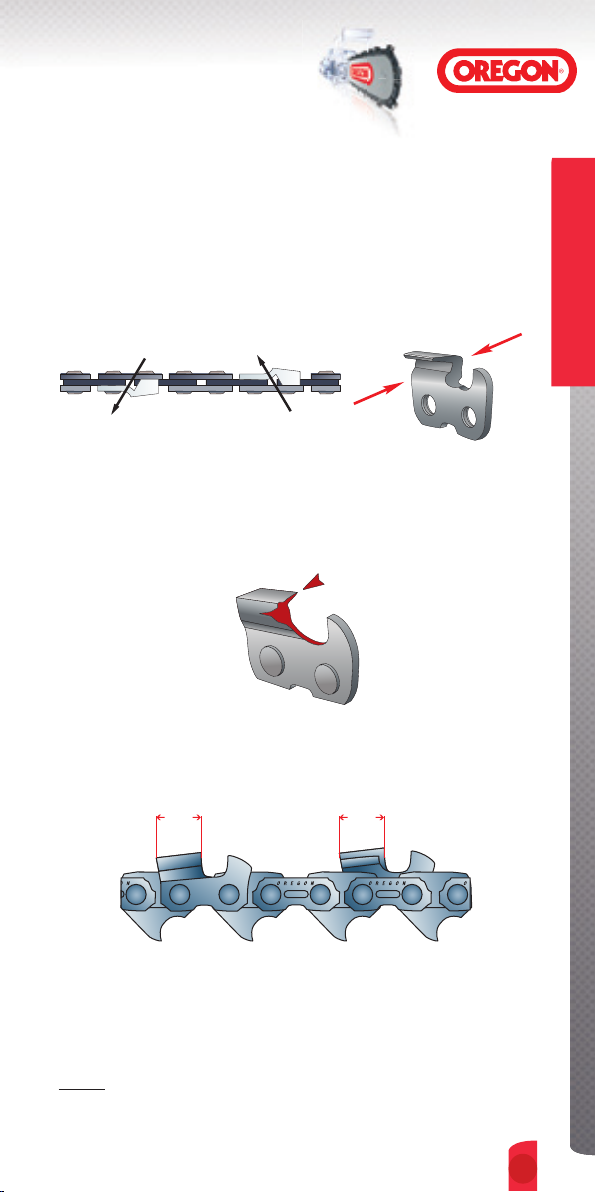
Saw Chains
HOW TO SHARPEN CUTTERS
➌
Sharpen cutters on one side of the chain first. File from the inside of
each cutter to the outside. Then turn your saw around and repeat
the process for cutters on the other side of the chain.
inside
➍
If damage is present on the chrome surface of top plates or side
plates, file back until such damage is removed.
➎
Keep all cutter lengths equal.
A
A=B
B
outside
Saw Chains
➏
Re-check depth gauges. If re-setting of the depth gauges is necessary,
follow instructions on pages 16 and 17.
NOTE: Do not file or alter the tops of kickback-reducing bumper
tie straps or bumper drive links.
19.
Saw Chains
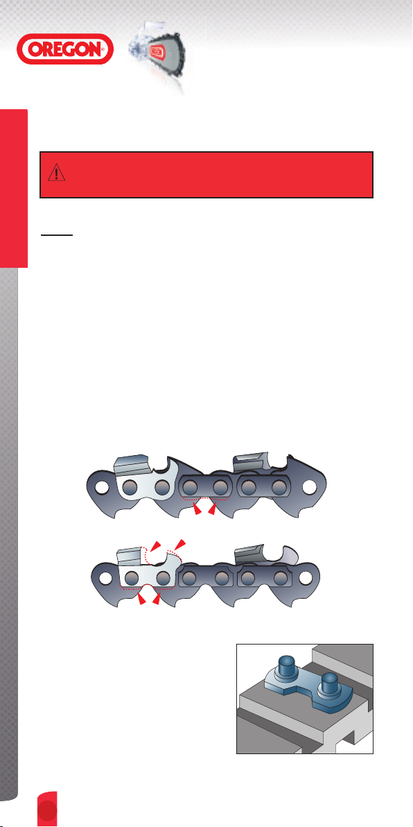
HOW TO INSTALL NEW CHAIN PARTS
Read the warnings on page 12.
Saw Chains
NOTE:
®
• Use only OREGON
parts which are the correct size and type for your chain.
➊
Remove rivets, and parts to be replaced, as shown under “How to
Break Out Rivets," pages 22 to 23. Never reassemble a chain with
old preset tie straps - always use new preset tie straps.
➋
If needed, file off bottom of new parts to match existing worn parts.
File new cutters back to match worn cutters. Do not file the tops of
kickback-reducing bumper tie straps or bumper drive links.
parts to repair OREGON® chain. And only use
➌
Place the preset tie strap on a flat outer
surface of a chain-breaker anvil. Be
sure the rivets are pointing up.
Introduction
IntroductionIntroduction
20.
 Loading...