

Page 1
1
GB
DIGIT AL WEATHER FORECASTER
WITH REMOTE THERMO-HYGRO
SENSOR AND RADIO CONTROLLED
CLOCK
MODEL NO.: BAR112HGA
USER’S MANUAL
INTRODUCTION
Congratulations on your purchase of the Weather forecaster with
cable free sensor and radio-controlled calendar clock BAR112HGA.
This unit has a large four-line liquid crystal display (LCD) for
displaying weather forecast information, in/outdoor temperatures
and relative humidity, radio frequency (RF) controlled calendar
clock and daily alarm. Also, the main unit can support up to three
remote sensors.
Other features include day of week display in three abbreviated
languages, crescendo alarm, and interchangeable clock display
modes.
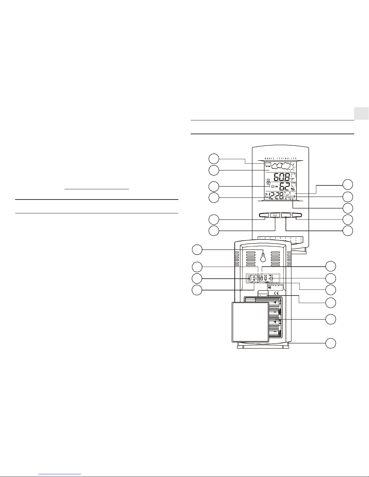
MAIN FEA TURES: MAIN UNIT
CHANNELMEMMODE / SE T
433MH CABLE FREE
Z
CHANNELMEMMODE / SET
A
D
EF
G
H
B
C
J
I
A1
K
L
M
N
O
P
S
T
RESET
R
Q
MAX
MAX
TEMP
RH
1
1
Tested To Comply
With FCC Standards
FOR H OM E OR OF F ICE U SE
MODEL NO. BA R112H GA
Page 2

2
GB
A . FRONT DISPLA Y
A four line easy-to-read LCD
A1. WEA THER FORECAST WINDOW
Graphically illustrates a weather forecast
B. [ ] BA TTERY-LOW INDICA T OR
Activates when the remote-sensor or main unit battery power
is low
C. [ ] RADIO-RECEPTION SIGNAL
Indicates the condition of radio reception
D . [ MODE/SET ] BUTTON
Changes the display mode of the clock and alters time/date
setting
E. [
] BUTTON
Displays the alarm time or changes the alarm set time
F. [ MEM ] BUTTON
Displays minimum and maximum temperature and
humidity readings and erases memory data
G. [ CHANNEL ] BUTTON
Toggles between the remote sensor channels
H . [ ((.)) ] ALARM ICON
Appears when the alarm time is displayed
I. [
1
] ALARM-ON ICON
Appears when the alarm is activated
J. US - TIME ZONE MAP ICON
Displays Pacific (P), Mountain (M), Eastern (E) or Central
(C) time-zone
K. WALL-MOUNT HOLE
For mounting the unit on a wall
TEMPERA TURE & RELA TIVE HUMIDITY ALARM :
( for Channel - 1 only )
L. [ ON/OFF ] BUTTON
Enables / disables HI/LO temp alarm and HI/LO % RH alarm
M. [ HI/LO ] BUTTON
- Set the upper or lower temperature and humidity alarm
limits
- Confirms alarm settings
N. [ s ] BUTTON
Advances the value of the settings for the HI/LO
temperature and humidity alarm
CLOCK :
O. [ s ] BUTTON
Advances the value of a setting
P. [ AL ON/OFF] BUTTON
Enables or disables the daily alarm
Q. [ ZONE ] BUTTON
Toggles between the 4 US time-zones : Pacific, Mountain,
Eastern or Central
R. [ RESET ] BUTTON
Returns all settings to default values
S. BATTERY COMP AR TMENT
Accommodates four (4) UM-3 or “AA” size batteries
T. REMOV ABLE TABLE ST AND
For standing the main unit on a flat surface
Page 3
3
GB
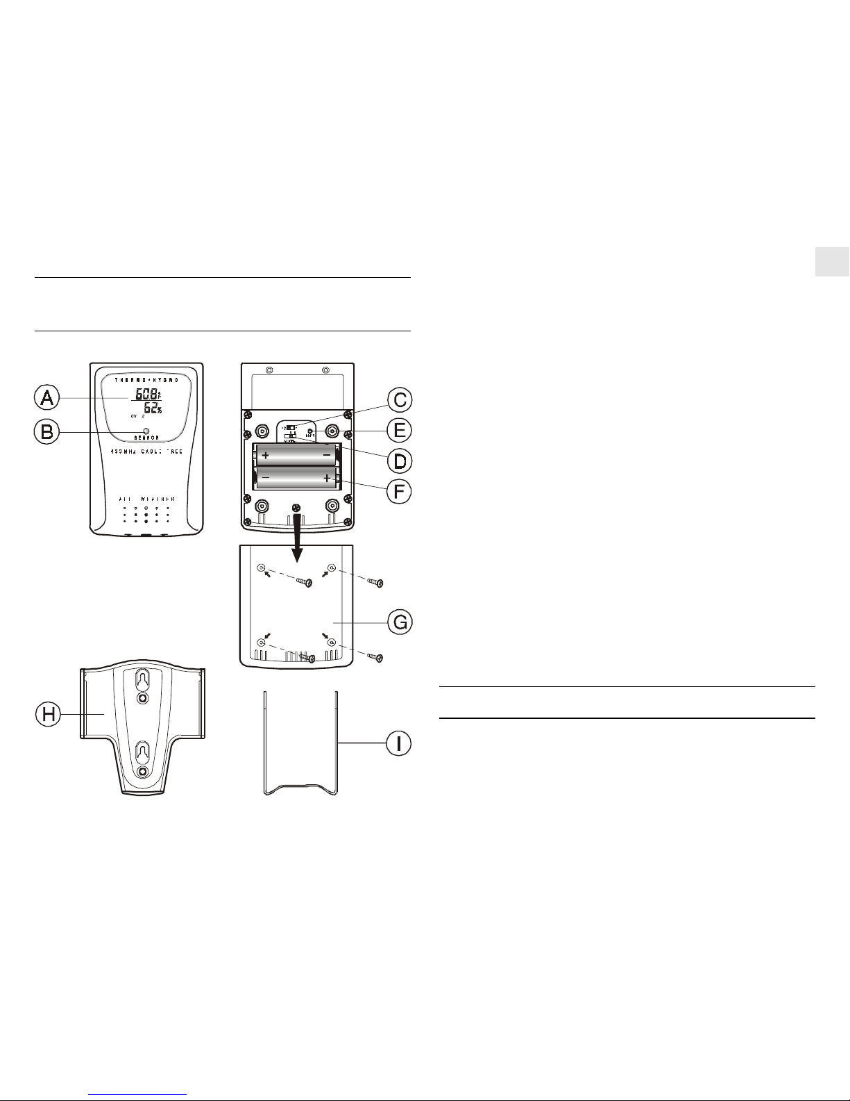
FEA TURES: REMOTE THERMO-HYGRO
SENSOR
A. TWO-LINE LCD
Displays the current temperature and humidity monitored by
the remote unit
B. LED INDICAT OR
Flashes when the remote sensor transmits a reading
C. °C/°F SLIDE SWITCH
Selects between Centigrade (°C) and Fahrenheit (°F)
D . CHANNEL SLIDE SWITCH
Select the remote sensor Channel 1, Channel 2 or Channel 3
E. RESET
Returns all user programmed settings to original factory set
values
F. BA TTERY COMP ARTMENT
Accommodates two (2) UM-3 or AA-size batteries
G. BA TTERY DOOR
H. WALL-MOUNT HOLDER
Supports the remote unit in wall-mounting
I. REMOVABLE TABLE ST AND
For standing the remote unit on a flat surface
BEFORE YOU BEGIN
For best operation,
1. Assign different channels to different remote units.
2. Insert batteries for remote units before doing so for the main unit.
3. Place the main unit as close as possible next to the remote unit,
reset the main unit after installing batteries. This will ensure
Page 4
4
GB
easier synchronization between the transmission and reception
of signals.
4. Position the remote sensor and main unit within effective
transmission range, which, in usual circumstances, range of 100
feet (30 meters) under ideal conditions.
Note that the effective range is vastly affected by the building
materials and where the main and remote units are positioned. Try
various set-ups for best result.
Though the remote sensors are weather resistant, they should be
placed away from direct sunlight, rain or snow.
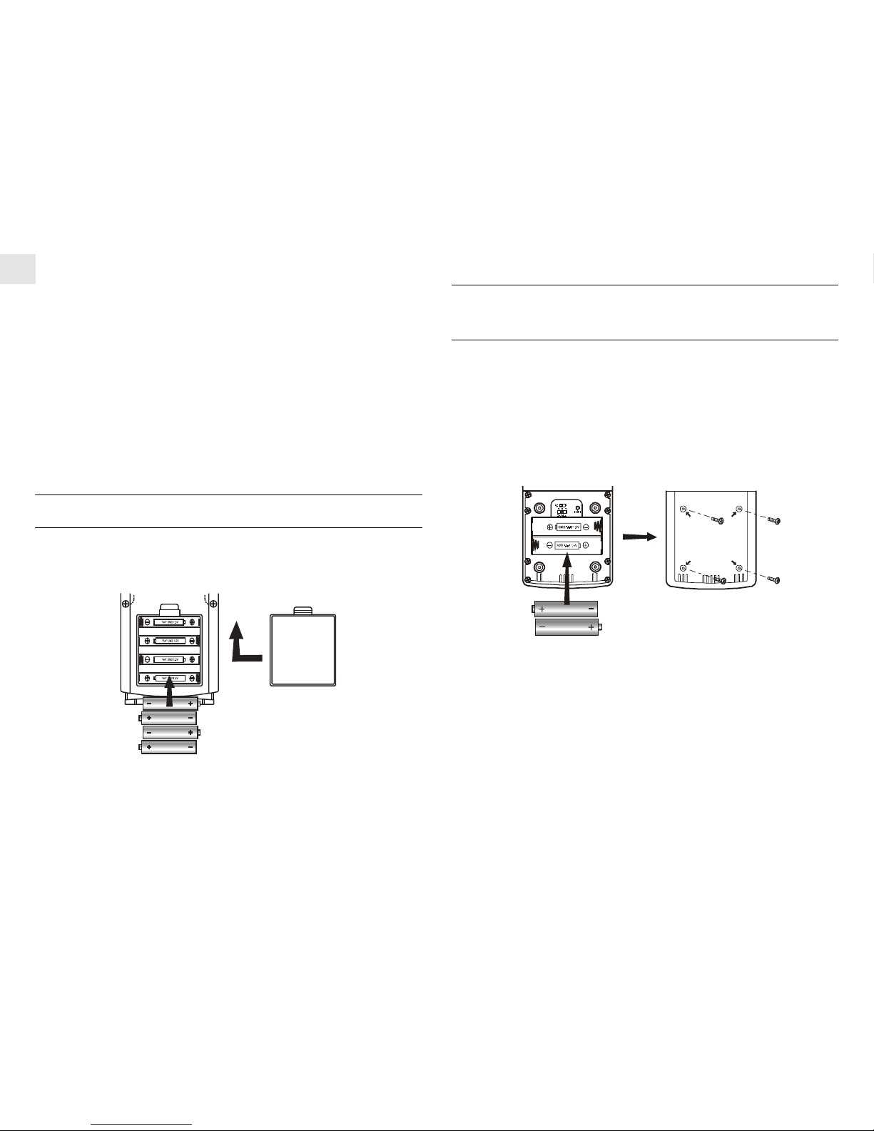
BA TTERY INST ALLA TION: MAIN UNIT
1. Gently lift up the tab on the battery compartment door.
2. Insert four (4) UM-3 or “AA” size batteries.
3. Replace the battery compartment door.
BA TTERY AND CHANNEL INST ALLA TION:
REMOTE UNIT
The remote thermo-hygro sensor unit uses two (2) UM-3 or “AA”
size batteries.
Follow these steps to install / replace batteries:
1. Remove the screws on the battery compartment.
2. Select the channel number on the [CHANNEL] slide switch.
3. Select the temperature display unit on the °C/°F slide switch.
4. Insert the batteries strictly according to the polarities shown
therein.
5. Replace the battery compartment door and secure its screws.
Replace the batteries when the low-battery indicator of the particular
channel lights up on the main unit. (Repeat the steps described in
section “BEFORE YOU BEGIN”)
Note that once a channel is assigned to a remote unit, you can only
change it by removing the batteries or resetting the unit.
Page 5
5
GB
LOW BA TTERY W ARNING
When it is time to replace batteries, the low-battery indicator will
be displayed for the selected channel.
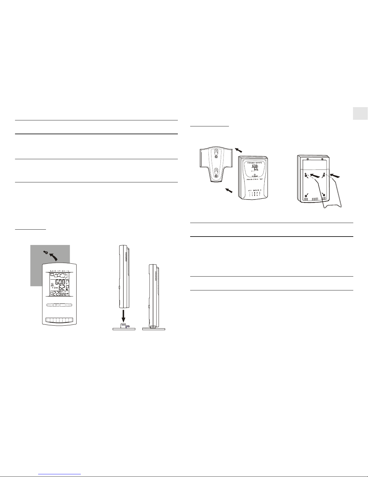
HOW TO USE THE T ABLE ST AND OR WALL
MOUNTING
The main unit has a removable table stand which when connected
can support the unit on a flat surface. Or you can remove the stand
and mount the unit on a wall using the recessed screw hole.
The remote sensor comes with a wall mount holder and a table stand.
Main unit
Wall-mount Table Stand
Remote unit
Wall-mount Table Stand
THE RESET BUTTON
This button is used when the unit is operating in an unfavorable
way or malfunctioning. To return all user programmed settings to
their original factory values, press [ RESET ] by using a blunt
stylus to hold down the button.
GETTING ST ARTED
Once batteries are placed in a given remote sensor unit, it will start
transmitting information at 40-second intervals.
For approximately a 3-minute duration, the main unit will
automatically search for signals once batteries are installed. Upon
successful reception, the individual channel temperature reading
will be displayed on the second line and the respective humidity
reading on the third line. The main unit will automatically update
its readings at about 40-second intervals.
433MH CABLE F REEZ
CHANNELMEMMODE / SET
MAX
MAX
TEMP
RH
1
1
Page 6

6
GB
If no signals are received, blanks “---” will be displayed and the
kinetic wave icon will not show.
To force a signal search:
• Press and hold [CHANNEL] & [MEM] for 2 seconds to
enforce a 3-minute search.
This is useful in synchronizing the transmission and reception of
the remote and main units.
Repeat this step whenever you find discrepancies between the
reading shown on the main unit and that on the respective remote
unit.
HOW TO CHECK REMOTE AND INDOOR
TEMPERA TURE & HUMIDITY
Display of readings from a remote sensor or the main unit is a onestep procedure. The remote sensor channel or the main unit display
is indicated in a box under the kinetic-wave icon.
T o display temperature / humidity readings fr om the main unit:
• Press [CHANNEL] until a dot is displayed in the box under the
kinetic-wave.
To display temperature / humidity readings from a remote
sensor:
• Press [CHANNEL] until the appropriate remote sensor channel
is displayed in the box under the kinetic-wave.
DISCONNECTED SIGNALS
If without obvious reasons the display for a particular channel goes
blank, press [CHANNEL] & [MEM] to enforce an immediate search.
If that fails, check:
1. The remote unit of that channel is still in place.
2. The batteries of both the remote unit and main unit. Replace as
necessary.
Note that when the temperature falls below freezing point, the
batteries of outdoor units will freeze, which will lower their
voltage supply and the effective range.
3. The transmission is within range and path is clear of obstacles
and interference. Shorten the distance when necessary.
TRANSMISSION COLLISION
Signals from other household devices, such as door bells, home
security systems and entry controls, may interfere with those of this
product and cause temporary reception failure. This is normal and
does not affect the general performance of the product. The
transmission and reception of temperature and humidity readings
will resume once the interference recedes.
Indoor
Display
Designated
Display
Remote
Display
Channel 1
Kinetic-wave
Icon
Remote
Display
Channel 2
Remote
Display
Channel 3
Page 7

7
GB
HOW TO READ THE KINETIC W AVE
DISPLA Y
The kinetic wave display shows the signal receiving status of the
main unit. There are three possible forms:
The unit is in searching mode.
Transmission data are securely
registered.
No signal received in search mode.
REMOTE SENSOR SCANNING
The unit can be set to automatically scan and display readings from
the remote sensors and indoor readings. When the remote-sensor
scanning mode is active, the display will show the readings from
one channel for about 4-second and then proceed to the next channel
display.
To activate the remote-sensor scanning mode:
• Press and hold [CHANNEL] for 2 seconds.
To deactivate the remote-sensor scanning mode:
• Press either [CHANNEL], [MEM], [HI/LO], [ s ], [ON/OFF]
(TEMP % RH AL)
COMFORT LEVEL INDICA T ORS
The comfort level indicators COM, WET or DRY will tell you if the
curent environment is comfortable, too wet or too dry.
The comfort indicator will appear on the display when the following
conditions are satisfied:
Indicator
displays
on the unit
Temperature
Range
20°C to 25°C
(68°F to 77°F)
-5°C -+ 50°C
(23°F - 122°F)
-5°C -+ 50°C
(23°F - 122°F)
Humidity
Range
40%RH70%RH
OVER70%RH
Below
70%RH
Shows that the
Current
Environment
Ideal range for
both relative
humidity and
temperature
Contains excess
moisture.
Contains
inadequate
moisture
No
Indicator
Less than
20°C( 68°F)
or More than
25°C (77°F)
40%RH
to
70%RH
No comment
COM
WET
DRY
Page 8

8
GB
TEMPERA TURE, HUMIDITY & PRESSURE
TREND INDICA TORS
The temperature-trend, humidity-trend and pressure-trend
indicators show the trends of collected readings. Arrows indicate
a rising, steady or falling trend.
Note: If the reading goes above or below the measuring range of the
main unit or the remote unit ( stated in specification), the display
will show “HHH” or “LLL”.
MAXIMUM AND MINIMUM TEMPERA TURE
AND HUMIDITY
The maximum and minimum recorded temperature and humidity
readings will automatically be stored in the memory.
To display the maximum and minimum display memory:
1. Select the channel to be checked.
2. Press [MEM] once to display the maximum temperature and
humidity and press [MEM] again to display minimum temperature
and humidity. The respective indicators, MAX or MIN will be
displayed.
T o clear the memory:
• Press and hold [MEM] for 2 seconds.
If you press [MEM] now, the maximum and minimum recordings will
have the same values as the current ones until different readings are
recorded.
HOW TO USE CHANNEL-1 TEMPERA TURE/
HUMIDITY ALARM
Upper and lower temperature and humidity limits for Channel-1 can
be set so that an alarm activates when the limits are exceeded.
The high and low temperature and humidity displays are selected
by sequentially pressing [ HI/LO ].
Rising
Arrow indicator
Humidity Trend
Steady Falling
Rising
Arrow indicator
Pressure Trend
Steady Falling
Rising
Arrow indicator
Temperature
Trend
Steady Falling
Page 9

9
GB
The high-low displays are as follows:
Sequence Respective Display
Pressing HI/LO once Enters HI temperature display
Pressing HI/LO twice Enters HI humidity display
Pressing HI/LO third time Enters LO temperature display
Pressing HI/LO fourth time Enters LO humidity display
To set a high or low temperature or humidity alarm:
1. Press [HI/LO], Channel-1 will be displayed.
2. Press [ s ] to set the temperature or humidity limit. Each press
will increase increments by one degree or percentage. Press and
hold the button for a rapid-scrolling sequence by increments of
five.
Note: The temperature range is from -50°C (-58°F) to +70°C
(158°F).
If this is the first time you set the limits, the lower limit will
start from -50°C (-58°F) and the upper limit +70°C (158°F).
Otherwise, the reading will start from the temperature last
selected.
The humidity range is from 2% to 98%.
If this is the first time you set the limits, the lower limit will
start from 2% and the upper limit 98%. Otherwise, the reading
will start from the humidity last selected.
3. Repeat the steps to set the upper temperature and humidity setting
and the lower temperature and humidity settings.
4. When finished, press [HI/LO] to set another limit or wait 16
seconds and the unit will automatically return to the normal
display. The respective HI, LO or both indicators will be
displayed to signify the status of the alarm.
If a channel other than channel-1 is selected, the display will switch
to channel-1 and flash when the alarm activates. If left untouched,
the alarm will activate for 1 minute. Press either [CHANNEL],
[MEM], [HI/LO], [ s ], [ON/OFF]
(TEMP % RH AL)
to momentarily stop the alarm. The alarm will activate again if the
limit continues to exceed the set limit.
Note: If a second limit is passed while an alarm is active, the first
alarm will complete its 1-minute cycle and the alarm will continue
to activate for a second minute to indicate that a second limit has
been surpassed.
To disable an alarm:
1. Enter the setting mode by pressing [HI/LO].
2. Then, press [ ON/OFF].
The alarm has been disabled. Display will show “---” to indicate
such deactivation and will not sound at the previously set limit.
To disable a sounding alarm:
• Press either [CHANNEL], [MEM], [HI/LO], [ s ], [ON/OFF]
(TEMP % RH AL)
Page 10

10
GB
WEA THER FORECAST FUNCTION
The unit is capable of detecting atmospheric pressure changes. Based
on collected data, it can predict the weather for the forthcoming 12
to 24 hours. The effective range covers an area of 18 to 30 miles.
NOTE:
1. The accuracy of a general pressure-based weather forecast is
about 70% to 75%.
2. The weather forecasts from this unit are predictions that cover
the next 12 to 24 hours. It may not necessarily reflect the current
situation.
3. The “Sunny” icon, implies clear weather.
CALENDAR CLOCK DISPLA Y MODES
The BAR112HGA supports 2 time display modes in the sequence
of:
MODE 1.
Hour-Minute-Second (of local time)
Month-Day (of local time)
MODE 2.
Hour-Minute-Day of the Week (of local time)
Month-Day (of local time)
Each press on the [MODE/SET] button will toggle the display in
the above order.
Note: The bottom line of the display will be replaced by the alarm
time if the [
] button is pressed.
ABOUT RADIO RECEPTION
The BAR112HGA is designed to automatically synchronize its
calendar clock when it is within range of the radio signal from the
U.S. Atomic clock.
When the unit is receiving radio signal, the RADIO RECEPTION
signal will start to blink. A complete reception generally takes
about 2 to 10 minutes, depending on the strength of the radio signal.
When the reception is complete, the RADIO RECEPTION signal
will stop blinking. The strength of the reception will remain until
the next scanning cycle takes place.
For better reception, place the clock away from metal objects and
electrical appliances to minimize interference.
If you wish to disable the auto-reception feature, press the
[ ZONE ] button for three seconds. The radio reception signal [
]
and the outline of the US-Map icon will disappear. The unit will
not respond to radio signals.
To enable the feature again, press the [
] (clock) button for three
seconds.
The radio reception signal [
] and the outline of the US-Map icon
will start blinking to initiate reception automatically.
Cloudy
SunnyForecast Rainy
Slightly Cloudy
Indicator
displays
on the unit
Page 11

11
GB
HOW TO SET THE CLOCK MANUALL Y
T o set the clock manually, hold [MODE/SET] for three seconds. The
hour digits will blink.
Press [
] (clock) to select the hour. Keep pressing the button to
increase the value rapidly.
Press [MODE/SET] to confirm. The minute digits will blink.
Repeat the same procedure to set the minutes, year, month, day and
display language.
Note: The time and date are displayed in 12-HOUR clock format.
For the language display , you can choose among English (E), French
(F) and Spanish (s).
For the US time zone, select the time-zone by using the [ZONE]
button to toggle Pacific, Mountain, Eastern or Central.
If there is a setting you do not wish to change, simply press [MODE/
SET] to bypass the setting.
When you are done, press [MODE/SET] to exit. The display will
return to the mode last chosen.
HOW TO SET AND ARM THE ALARMS
The BAR112HGA has a daily alarm function.
To set an alarm:
1.
Press [ ] once to enter the Alarm display mode.
2. Press and hold [ ] for three seconds. The hour digits will
blink.
3. Enter the hour using [
]
4. Press [
]. The minute digits will blink.
5. Enter the minutes using [
]
6. Press [
] to exit. The [ ] icon for the alarm chosen will
be displayed indicating the alarm set above is now armed.
You can also arm or disarm an alarm by pressing the
[ AL ON/OFF ] button.
When an alarm is armed, it will go off at the set time.
The four-step crescendo function allows the alarm to start off gently
and step up its intensity every 20 seconds for four times. Without
interruption, the alarm will sound for a total of two minutes. If no
key is pressed to turn off the alarm within these 2 minutes, the alarm
will sound once more after 8 minutes.
-
Strong
-
Weak
-
No signal
-
Receiving
Page 12

12
GB
HOW TO STOP AN ALARM
To stop an alarm, you can use either press [ ] button or
[ AL ON/OFF ] button.
Pressing [
] will stop the alarm, which is still armed and will
activate at the set time the following day.
If [ AL ON/OFF ] button is pressed instead, the alarm will be stopped
and deactivated all together.
NOTE ON °C AND °F
The temperature display designation of °C or °F on the main display
unit will override the display selection made on the remote sensor.
Whatever the display unit of the remote sensor is, it will only apply
to the remote sensor itself and the temperature unit will automatically
be converted to the one of the main unit. (i.e. °F)
MAINTENANCE
When handled properly, this unit is engineered to give you years
of satisfactory service. Here are a few product care instructions:
1. Do not immerse the unit in water. If the unit comes in contact
with water, dry it immediately with a soft lint-free cloth.
2. Do not clean the unit with abrasive or corrosive materials.
Abrasive cleaning agents may scratch the plastic parts and
corrode the electronic circuit.
3. Do not subject the unit to excessive: force, shock, dust,
temperature, or humidity . Such treatment may result in
malfunction, a shorter electronic life span, damaged batteries, or
distorted parts.
4. Do not tamper with the unit’s internal components. Doing so
will terminate the unit’s warranty and may cause damage. The
unit contains no user-serviceable parts.
5. Only use new batteries as specified in this instruction manual.
Do not mix new and old batteries as the old batteries may leak.
6. Read this instruction manual thoroughly before operating the
unit.
SPECIFICATIONS
T emperature Measur ement
Main unit
Indoor T emperature measurement
Proposed operating range : -5.0°C to +50.0°C
(23.0°F to 122.0°F)
Temperature resolution : 0.1°C to (0.2°F)
Relative Humidity Operating : 25% RH to 90% RH
range
T emperature Display in °F format
Remote thermo-hygro unit
Proposed operating range : -20.0°C to +60.0°C
(-4.0°F to 140.0°F)
Temperature resolution : 0.1°C (0.2°F)
Relative Humidity Operating : 25% RH to 90% RH
range
Page 13

13
GB
Power
Main unit : use four (4) UM-3 or “AA”
1.5V battery
Remote sensing unit : use two (2) UM-3 or “AA”
1.5V battery
Weight
Main unit : 6.6 ounces (without battery)
Remote sensing unit : 2.6 ounces (without battery)
Dimension
Main unit : 6.44" x 3.48" x 1.12" (LxWxD)
Remote sensing unit : 4.2" x 2.8" x 0.84" (L x Wx D)
NOTE ON COMPLIANCE
This device complies with Part 15 of the FCC Rules. Operation is
subject to the following two conditions: (1) This device may not
cause harmful interference, and (2) This device must accept any
interference received, including interference that may cause
undesired operations.
Warning: Changes or modifications to this unit not expressly
approved by the party responsible for compliance could void the
user’s authority to operate the equipment.
FCC :
NOTE: This equipment has been tested and found to comply with
the limits for a Class B digital device, pursuant to Part 15 of the FCC
Rules. These limits are designed to provide reasonable protection
against harmful interference in a residential installation. This
equipment generates, uses and can radiate radio frequency energy
and, if not installed and used in accordance with the instructions,
may cause harmful interference to radio communications.
However, there is no guarantee that interference will not occur in a
particular installation. If this equipment does cause harmful
interference to radio or television reception, which can be determined
by turning the equipment off and on, the user is encouraged to try
to correct the interference by one or more of the following measures:
o Reorient or relocate the receiving antenna.
o Increase the separation between the equipment and receiver.
o Connect the equipment into an outlet on a circuit different from
that to which the receiver is connected.
o Consult the dealer of an experienced radio/TV technician for
help.
Company Name: Oregon Scientific, Inc.
Address: 19861 SW 95th Place, Tualatin, Oregon 97062, USA
Telephone Number: (1)503-6398883
Name and model number of the product: Digital Weather
Forecaster with Remote Thermo-Hygro sensor and Radio Controlled
Clock BAR112HGA
Page 14

14
GB
CAUTION
— The content of this manual is subject to change without
further notice.
— Due to printing limitation, the displays shown in this
manual may differ from the actual display .
— The contents of this manual may not be reproduced without
the permission of the manufacturer.
CUSTOMER ASSISTANCE
Should you require assistance regarding this product and its
operation, please contact our customer care department at
800-853-8883 or via email at helpme@oscientific.com.
WARRANTY
This product is warranted to be free of manufacturing defects for a
period of 1 year from date of retail purchase. Defective product
should be directed to the place of retail purchase for exchange.
Should this not be possible, contact our customer care
department for assistance and a return material authorization. No
returns may be made without a return authorization. Please retain
your retail receipt as you may be asked to provide a copy of it for
proof of date purchased.
This warranty does not cover product subjected to abuse,
misuse, accidental damage or tampering.
Page 15

15
GB
Instruction Manual
****
Mode D'emploi
****
Bedienungsanleitung
****
Manuale di Istruzioni
****
Instrucciones de Funcionamiento
MODEL: BAR112HGA
DIGIT AL WEATHER FORECASTER
WITH REMOTE THERMO-HYGRO SENSOR AND RADIO
CONTROLLED CLOCK
 Loading...