

Page 1
TOP WEATHER STATION
MODEL: BAA928U
USER’S MANUAL
INTRODUCTION
Congratulations on your purchase of the BAA928U Top Weather
Station. The BAA928U is all all-in-one weather device and clock.
The BAA928U, a weather forecasting device, and has several weather
related functions. One function is that it takes and records temperatures. Using the remote thermo-sensor, included with your purchase, the unit can simultaneously monitor two temperature readings. The unit will show temperature trends and record maximum
and minimum temperature readings.
Another weather function is the humidity readings. It shows the
indoor relative humidity and rates the comfort level. It can retain
the maximum and minimum relative humidity readings.
A built-in barometer displays the atmospheric pressure with a userselect altitude adjustment. A bar graph shows the pressure trend for
the last 24 hours.
The unit includes a moon phase scanner. This feature graphically
illustrates the current moon phase and lets you check the moon
phase of any date between 1990 and 2089.
Other features of the BAA928U include a clock and calendar, HiGlo
backlight, extra-large liquid crystal display (LCD), and a daily
crescendo alarm with an eight minute snooze function.
No wire installation is required between the main and remote units.
As the BAA928U operates at 418 MHz, it can be used in the USA and
most places in Continental Europe.
GB
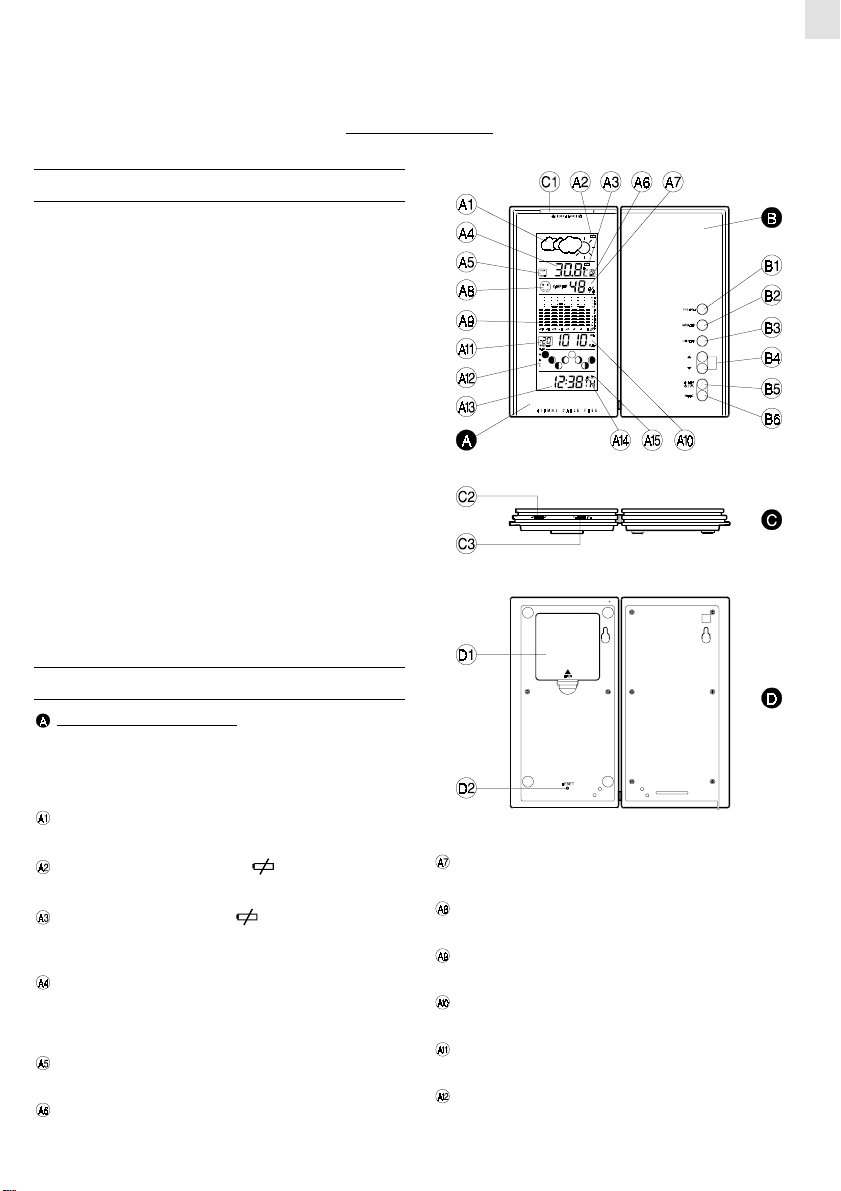
MAIN FEATURES : MAIN UNIT
LEFT PANEL AND DISPLAY
The extra-large LCD occupies the left panel. The LCD is subdivided into seven easy-to-read sections. Each section has
specific purposes that relate to weather functions, or clock/
calendar functions.
WEATHER FORECAST WINDOW
Graphically illustrates a weather forecast
MAIN UNIT BATTERY LOW ( ) INDICATOR
Lights up and blinks when batteries of the main unit are low
REMOTE BATTERY LOW ( ) INDICATOR
Lights up and blinks when the batteries of the remote unit are
low
TEMPERATURE WINDOW
Shows current temperatures, minimum/maximum temperatures,
temperature readings from the remote sensor, and temperature
trends
TEMPERATURE TREND ARROWS
Indicates the trend of temperature changes
IN/OUT REMOTE INDICATOR
Indicates if the current temperature is displayed as indoors or
outdoor-remote
RELATIVE HUMIDITY WINDOW
Displays the indoor relative humidity
COMFORT INDICATOR
Indicates the comfort level of the indoor relative humidity
ATMOSPHERIC PRESSURE BAR GRAPH
Indicates the atmospheric pressure for the latest 24 hour period
ATMOSPHERIC PRESSURE WINDOW
Displays the current atmospheric readings
PRESSURE HISTORY INDICATOR
Indicates the pressure history of previous hours
MOON PHASE SCANNER
Graphically illustrates the phases of the, and moon
phases for other specified dates
1
Page 2
GB
MODE WINDOW
Displays the current time and date
ALARM ICON "AL"
Appears when the alarm is displayed
ALARM ON ICON
Appears when the alarm is activated
RIGHT PANEL AND CONTROL BUTTONS
The front left panel has dual purposes. First, it can be used as a
support when the unit is positioned on a flat horizontal surface. This panel houses five commonly used control buttons.
Placed vertically along the right lower section of the panel,
they are used to access or input information.
TEMPERATURE (THERMO) BUTTON
Sets the indoor or outdoor-remote temperature mode
MEMORY BUTTON
Sets minimum and maximum temperature readings, indoor
relative humidity readings, and erases memory data
HISTORY BUTTON
Used to obtain previous air pressure readings
UP ( ) DOWN ( ) BUTTON
Sets the increase or decrease in the value of a setting, or to scan
moon phase data.
ALARM OFF / ON BUTTON
Displays the alarm time or sets the alarm status
MODE BUTTON
Changes the display mode of the clock, alters time/date
data, and altitude
OTHER SWITCHES AND CONTROLS
SNOOZE / LIGHT BAR
Activates the snooze function, functions to turn on the backlight
°C/°F SLIDE SWITCH
Selects between Centigrade (°C ) or Fahrenheit (°F) display
PRESSURE UNIT SLIDE SWITCH
Selects between mb/hPa or inHg display
BACK PANELS
BATTERY COMPARTMENT
Accommodates four UM-3 or “AA” size batteries
RESET SLOT
Resets the unit by returning all setting to their default values
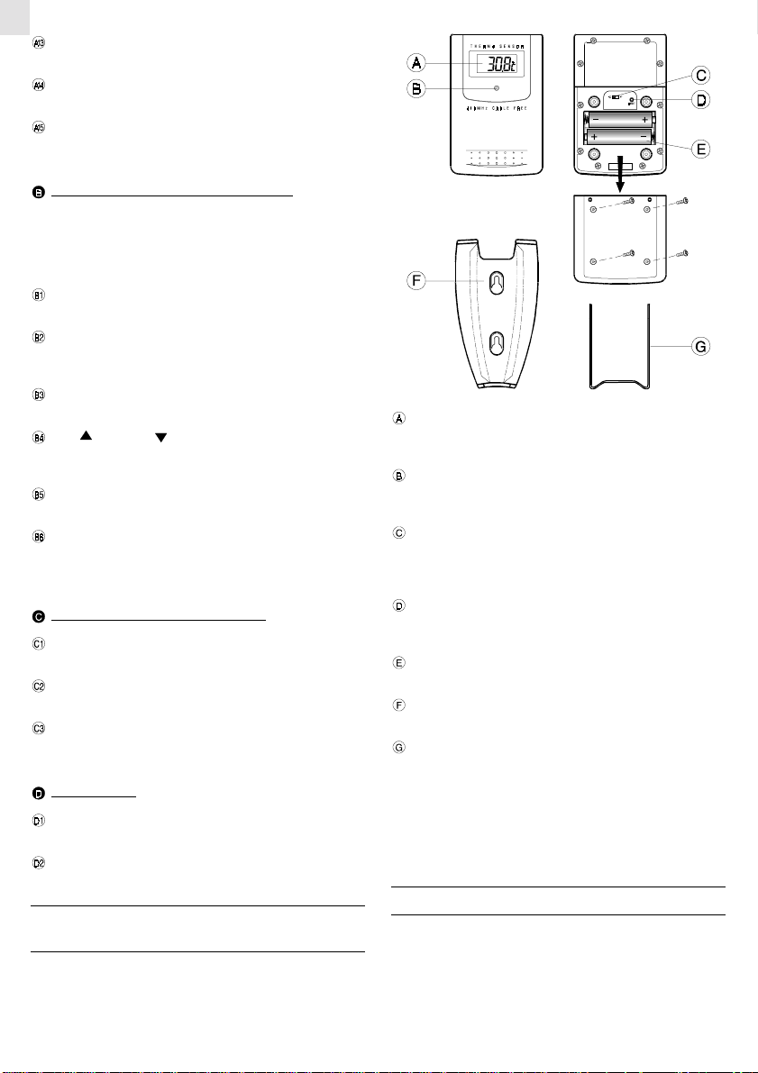
MAIN FEATURES :
REMOTE SENSOR UNIT
The remote sensor is an independent component. It comes with a
wall-mount holder and removable table stand.
LCD
The LCD window, located on the front upper section of the
remote unit, displays the current temperature reading
LED INDICATOR
A small red light located under the LCD window indicates when
the unit is transmitting a signal
°C/°F SLIDE SWITCH
Located inside the battery compartment, this switch enables
the a selection between Centigrade (°C) or Fahrenheit (°F)
display
RESET SLOT
Also located inside the battery compartment, this slot returns
all settings to default settings
BATTERY COMPARTMENT
Accommodates two UM-4 or “AAA” size batteries
WALL-MOUNT HOLDER
A plastic device for mounting the remote sensor to a wall.
REMOVABLE TABLE STAND
A removable stand for mounting the remote sensor on a flat
horizontal surface
Note: Also located inside the battery compartment is a channel
switch. The channel switch is used when there is more than one
remote sensor. For use of one remote sensor, use the factory
setting of one.
BEFORE YOU BEGIN
For best operation:
1. Insert batteries for the remote unit first. Then proceed with
inserting the batteries for the main unit.
2. Position the remote unit and the main unit within effective
transmission range. In usual circumstances, the effective range
is 30 meters.
2
Page 3
3. Though the remote unit is weather proof, it should be placed
away form direct sunlight, rain or snow.
BATTERY INSTALLATION :
REMOTE UNIT
The remote unit uses two (2) UM-4 or “AAA” size batteries.
Installation:
1. Remove the screws on the battery compartment.
2. Insert the batteries strictly according to the polarities shown
inside the battery compartment.
3. Select the desired temperature scale by switching the °C/°F
switch located inside the battery compartment.
4. Replace the battery compartment door and secure the screws.
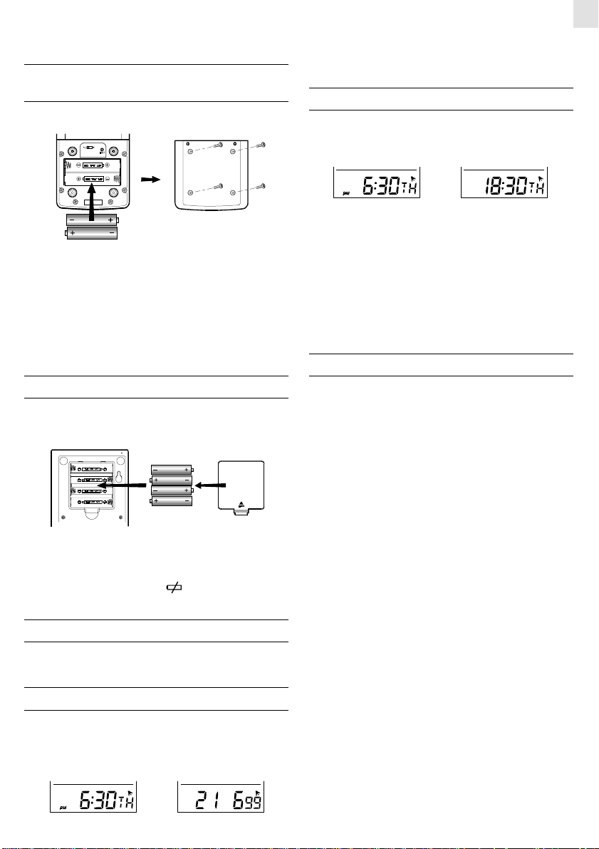
BATTERY INSTALLATION : MAIN UNIT
1. Gently press and lift the tab on the battery compartment door.
2. Insert four UM-3 or “AA” size batteries.
Pressing ALARM button during any of these modes will change
GB
the display to show the alarm time. Another press will activate or
deactivate the alarm. press MODE to go back to the time and date
display.
HOW TO MANUALLY SET THE CLOCK
When the current time is displayed, press MODE, and hold for
three seconds. The 12-hr or 24-hr digits will flash. Use the UP/
DOWN button to make a selection.
12 hour 24 hour
Press MODE again, the “hour digits” will flash. Use the UP/DOWN
button to enter the hours. Holding down either the up or down
position will increase or decrease the value rapidly.
Press MODE again, the “minute digits” will flash. Again, use the up
UP/DOWN button to change the minutes.
Press MODE to confirm and exit.
Note: When changes are made to the clock settings, the seconds
will start from zero.
HOW TO SET THE CALENDAR
The calendar is part of the clock section of the LCD. To access the
calendar:
1. Press MODE button until the calendar settings are displayed
(day, month, year).
2. Press MODE and hold for three seconds, to make changes to
the day, month, year settings.
3. Replace the battery compartment door.
Note: For both the remote sensor and the main unit, replace
batteries when they are low. The [
temperature reading will light up when the batteries are low.
] indicator of the outdoor
HOW TO USE THE BACK-LIGHT
Press SNOOZE/LIGHT bar once. The back-light will be turned on
for five seconds.
TIME DISPLAY MODES
The current time and date can be displayed in three modes: hour,
minute, second; hour, minute, day-of-the-week; or day, month,
year.
Press MODE button to change from one mode to the other.
hour, minute, day-of-the-week day, month, year
Note: The altitude compensation function and the calendar function are inter-linked. When inputting calendar changes, the unit
will first switch to the altitude compensation function.
If the altitude setting is correct, proceed to the calendar function as
follows:
Press MODE button again, the year digits will flash. Enter the
appropriate year using the UP/DOWN button.
Press MODE . The day (D) and month (M) symbols will flash. The
unit provides an option that allows either the day or the month to
be indicated first. Using the UP/DOWN button, select whether the
calendar reads as day, month, year; or month, day, year.
Press MODE and follow the same procedure to set the month and
day-of-the-month.
Days of the week can be can be indicated in five different languages.
Press MODE to change the language setting. The E, I, D, F or S
language indicator will flash. Use the UP/DOWN button to select
E for English, I for Italian, D for German, F for French, or S for
Spanish (see language chart illustration).
Press MODE and the day-of-the-week will flash. Use the UP/DOWN
button to enter the day.
Press MODE again to confirm and exit.
3
Page 4

GB
MULTILINGUAL DAY-OF-THE-WEEK
FUNCTION
The day-of-the-week can be expressed as an abbreviation in five
different languages. The languages and their selected abbreviations for each day of the week are shown in the language chart
below. To select a particular language follow the instructions in the
“ HOW TO SET THE CALENDAR ” section.
German
ABOUT ALTITUDE SETTING
Changes to the altitude compensation reading can be made when
the altitude section of atmospheric pressure window is flashing.
Use the UP/DOWN button to enter the desired value.
For users who are at elevations other than sea level, such as mountainous areas, sea level barometric pressure do not apply. The
atmospheric pressure setting will need to be set to the corresponding elevation. Barometric pressure settings can be set to accommodate elevations between -100 to 2500.
As previously mentioned, to make changes to the altitude setting:
1. Press MODE button until the calendar settings are displayed
(day, month, year).
2. Press MODE and hold for three seconds, when the altitude
section flashes, use the UP/DOWN button to enter the appropri-
ate setting.
ATMOSPHERIC PRESSURE
The atmospheric pressure section is the third section from the
bottom. The corresponding bar graph occupies the middle section
of the LCD window.
The atmospheric pressure can be displayed in mb/hPa or inHg. Use
the atmospheric pressure slide switch, to make the appropriate
change.
If you want to know the pressure history for a particular hour
during the past 24 hours, press HISTORY button. Each press will
go back by an hour. Holding down the button will increase the
value rapidly.
The recorded atmospheric changes for the past 24 hours are displayed, in a bar graph in the middle of the LCD, directly above the
atmospheric pressure window.
HOW TO SET AND ACTIVATE
THE ALARM
Press ALARM button to display the alarm time.
Press ALARM and hold for three seconds to make changes to the
alarm time.
Enter the value for the hour digits. Press ALARM and enter the
value for the minute digits. Press ALARM to exit.
The alarm is automatically activated.
To deactivate the alarm, press ALARM to show the alarm time, then
press ALARM again to deactivate it.
Press MODE to exit.
Note: A small icon (
section of the LCD indicates that the alarm is set. The alarm is
deactivated if the icon is not shown.
) in the upper right corner of the time/date
ALARM AND SNOOZE FUNCTION
When the alarm function is active, the unit will alarm at the set time.
The display will light up for five seconds with the ALARM ON icon
flashing.
The alarm function has a built in crescendo type alarm system.
Subsequently, the alarm starts off gently and steps up in intensity
in three stages. Without interruption, the unit will alarm for two
minutes.
To stop the alarm, press any button. However, if the SNOOZE/
LIGHT bar is pressed, the SNOOZE function will be triggered. The
alarm will stop and the ALARM ON icon blinks for eight minutes
before the unit alarms again.
To deactivate the SNOOZE function, press the ALARM button.
CHECKING INDOOR AND
OUTDOOR-REMOTE TEMPERATURES
The indoor and outdoor temperature readings, temperature maximum/minimum indicator, and the temperature trend arrow are all
part of the temperature section of the LCD (second section from the
top).
To measure indoor temperatures, press the THERMO button until
the IN indicator is displayed.
To measure the temperature at the location of the remote sensor,
press the THERMO button until the OUT indicator is displayed.
The temperature can be shown in Centigrade (°C) or Fahrenheit
(°F). It is selected on the °C/°F slide switch (located on the lower
side on the left side of the left panel). Slide the switch to °C for
Centigrade or °F for Fahrenheit.
4
Page 5

The BAA928U is able to measure temperatures within -50°C
(-58°F) and +70°C (+158°F). If the temperature goes above or
below these amounts, the display will show a flashing ”70” or
“-50”.
NOTE ON OUTDOOR-REMOTE
TEMPERATURE
Once batteries are in place for the remote unit, it will start transmitting samplings at 30-second intervals.
If no signals are received when the outdoor-remote temperature is
selected, blanks will be displayed. Press and hold the THERMO
button to enforce a search. This is useful in synchronizing the
transmission and reception of the remote and main units.
If that fails, check if the remote unit is still in place. Make sure the
transmission is within range and path is clear of obstacles and
interference.
Repeat this procedure whenever you find discrepancies between
the reading shown on the main unit and the remote unit.
NOTE ON °C AND °F
The outdoor temperature display on the main unit is determined by
the selection of the °C/°F slide switch of the main unit. Whatever
selection is on the remote sensor, it will only apply to the remote
sensor. The temperature will be automatically converted to the
selected setting of the main unit.
MAXIMUM AND MINIMUM
TEMPERATURES
The maximum and minimum recorded temperatures will be automatically stored in memory. To display them, press MEMORY to
alternate between the maximum, minimum and current temperatures. The respective MAX or MIN indicator will be displayed.
To clear the memory, press MEMORY button and hold for three
seconds. The maximum and minimum recorded temperatures will
be erased. Subsequently, if you press MEMORY after the memory
has been erased, the maximum and minimum temperature will have
the same values as the current reading.
TEMPERATURE TREND
The temperature trend indicator shows the trend of temperatures
collected at that particular remote sight. Three trends, rising, steady
and falling, will be shown.
Indicator
displays on
the unit
Forecast
NOTE:
1. The accuracy of a general pressure-based weather forecast is
about 70% to 75%.
2. The weather forecasts from this unit are predictions that cover
the next 12 to 24 hours. It may not necessarily reflect the current
situation.
3. The “Sunny” icon, as applies to night time, implies clear weather.
Sunny Slightly Cloudy Cloudy Rainy
INDOOR RELATIVE HUMIDITY
Third from the top, the indoor relative humidity is automatically
detected. The reading is displayed in the relative humidity window.
Like temperature, the maximum and minimum relative humidity
will be stored in memory. Use the MEMORY button to alternate
between the maximum, minimum, and current relative humidity.
The respective MAX and MIN indicator will be displayed.
To clear the memory, press MEMORY button and hold for three
seconds. The maximum and minimum temperatures will be erased.
COMFORT LEVEL
The comfort level is based on the recorded relative humidity. An
icon will be display the level of comfort as: comfortable, wet, or
dry.
HOW TO USE
THE MOON PHASE SCANNER
The moon phase section of the LCD, second from the bottom, is a
moon phase scanner. Illustrated are eight moon phases in sequence
from a new moon to waning crescent. The moon that is flashing is
the moon for that particular day.
The eight phases are:
GB
Arrow
indicator
Temperature
Trend
Steady FallingRising
WEATHER FORECAST
The unit is capable of detecting atmospheric pressure changes, and
based on collected data, it can predict the weather for the forthcoming 12 to 24 hours. The effective range covers an area of 30 to 50 km.
New Moon
Waxing Crescent
First Quarter
Waxing Gibbous
5
Waning Crescent
Last Quarter
Waning Gibbous
Full Moon
Page 6

GB
To check the moon phase for a particular day, press the UP/DOWN
button. The clock will enter moon phase scanning mode.
Use the UP/DOWN button to locate the date you want to check. The
calendar will be day-driven in this mode.
You can go back in time or travel to the future, the moon phase for
any day between the hundred years from 1990 to 2089 can be
accessed. The corresponding moon phase will appear immediately
on the screen.
The unit will return to the last display mode when the UP/DOWN
button is left idle for 15 seconds.
HOW TO WALL MOUNT OR USE
THE TABLE STAND
The unit can be wall-mounted using its recessed screw holes or
place on a flat surface using its table and control stand. To use the
stand, lay the control panel on a flat surface. Then adjust the angle
of the display panel for best display and support.
Wall-mount
1. Do not immerse the unit in water. If the unit comes in contact
with a water, dry it immediately with a soft lint-free cloth.
2. Do not clean the unit with abrasive or corrosive materials.
Abrasive cleaning agents may scratch the plastic parts and
corrode the electronic circuit.
3. Do not subject the unit to excessive: force, shock, dust, temperature, or humidity. Such treatment may result in malfunction, a shorter electronic life span, damaged batteries, or distorted parts.
4. Do not tamper with the unit’s internal components. Doing so
will terminate the unit’s warranty and may cause damage. The
unit contains no user-serviceable parts.
5. Only use new batteries as specified in this instruction manual.
Do not mix new and old batteries as the old batteries may leak.
6. Read this instruction manual thoroughly before operating the
unit.
TIME ZONE AND OFFSET TABLE
Table stand
HOW TO RESET THE UNIT
The RESET slot allows you to return all settings to factory values.
Accessing the slot is required only when the unit is not operating
in a favorable way such as in the rare case of a malfunction.
The RESET slot is located inside the battery compartment door. To
use the button,
1. Lift open the battery compartment door.
2. Place a blunt stylus into the slot and press.
3. Replace the battery compartment door.
MAINTENANCE
When handled properly, this unit is engineered to give you years
of satisfactory service. Here are a few product care instructions:
SPECIFICATIONS
• Temperature Measurement
Main unit
Indoor Temperature measurement
Displayed IN temperature range : -50.0°C t +70.0°C
(-58.0°F to 158.0°F)
Proposed operating range : -5.0°C to +50.0°C
(23.0°F to 122.0°F)
Temperature resolution : 0.1°C (0.2°F)
Remote Temperature measurement
Displayed OUT temperature range : -50.0°C to +70.0°C
(-58.0°F to 158.0°F)
Proposed operating range : -5.0°C to +50.0°C
(23.0°F to 122.0°F)
Temperature resolution : 0.1°C (0.2°F)
6
Page 7

Remote unit
Displayed range : -50.0°C to +70.0°C
(-58.0°F to 158.0°F)
Proposed operating range : -20.0°C to +60.0°C
(-4.0°F to 140.0°F)
Temperature resolution : 0.1°C (0.2°F)
RF Transmission Frequency : 418 MHz
No. of Remote unit : one
RF Transmission Range : 30 meters
Temperature sensing cycle : around 30 seconds
• Relative Humidity Measurement
Indoor relative humidity measurement ranging from 25%
RH to 95% RH
• Barometric Pressure Measurement
Pressure measuring range : 795 to 1050 mb/ hPa
(23.48 to 31.01 inHg)
Pressure sampling cycle : 15 minutes
• Moon Phase Functions
Moon Phase Scanner Range : From 1990 to 2089
• Power
Main unit : use four (4) UM-3 or “AA”
1.5V alkaline battery
Remote sensing unit : use two (2) UM-4 or “AAA”
1.5V alkaline battery
GB
CAUTION
— The content of this manual is subject to change without
further notice.
— Due to printing limitation, the displays shown in this
manual may differ from the actual display.
— The manufacturer and its suppliers held no
responsibility to you or any other person for any damage
expenses, lost profits, or any other claim arise by using
this product.
— The contents of this manual may not be reproduced
without the permission of the manufacturer.
• Weight
Main unit : 306 gm
Remote sensing unit : 100 gm
• Dimension
Main unit : 182(L) x 133(W) x 28(T) mm
Remote sensing unit : 92(L) x 60(W) x 21(T) mm
NOTE ON COMPLIANCE
This product complies to standards and specifications of BZT, FCC
and article number 334 of PTT.
7
 Loading...