

OREC LS 280, LS360, LS461 Owner's Manual
OWNER’S MANUAL
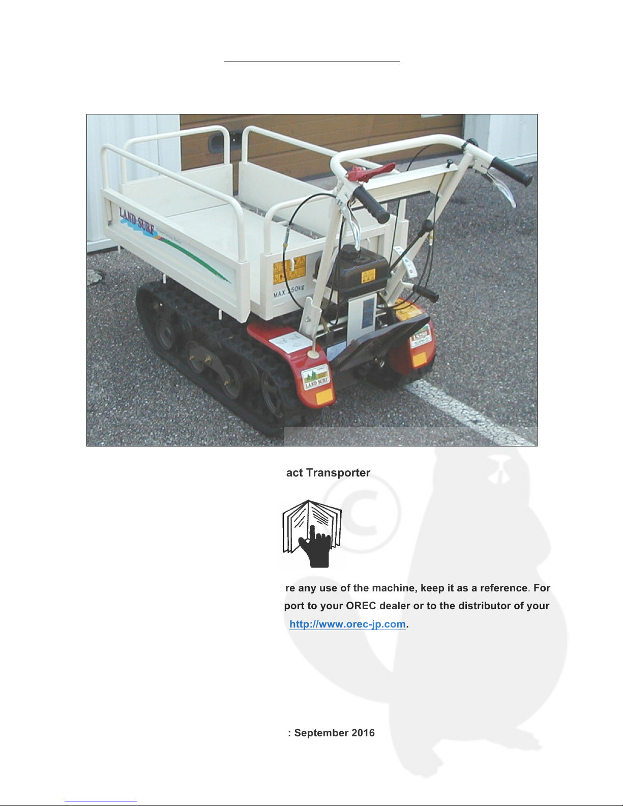
Transporter LS 280 / LS360 / LS461
Compact Transporter
Read this instuction manual carefully before any use of the machine, keep it as a reference. For
any question about this manual, please report to your OREC dealer or to the distributor of your
country or to : http://www.orec-jp.com.
Update : September 2016

© SAT – 09/2006
2
“Only the English version of this manual can be used as a reference.”
INTRODUCTION
Forword to the user
Read this manual before any use of your mower, only the herein instructions shall help you to achieve an
efficient and safe work.
A safe use will only result from the manner you will use the machine in accordance with the restrictions
described in this manual. Thus, you must know and follow all the safety measures in this manual and
those relating to the use of your mower.
The mower that you have just bought has been designed and manufactured for your entire satisfaction.
As any other mechanical machine, it requires a proper maintenance and must be kept clean. Grease the
machine like indicated. Follow the rules and safety indications as described in this manual and as showed
on the preventive instruction stickers.
About maintenance, always mind that your OREC dealer has the skills, the genuine parts and the
necessary tools to solve the possible problems.
Use only the OREC original parts : “ non genuine ” parts will not assure you of a correct and safe working
and are likely to make the guarantee null and void. Write the name and the serial number of your
machine hereunder :
MODEL :.......................................................................................
SERIAL NUMBER (refer to the pictures herein) :.........................
Always mention these informations to your dealer in order to obtain the right parts.
Concerned about constant progress, OREC keeps the right to modify the machines without being
compelled to modify those already sold.
The illustrations and characteristics in this manual might lightely differ from your machine because of the
constant improvements made by our production department.
In this manual, the left and the right hand or the rear and the front position are determined according to
the mower handlebar.
All along this manual the word IMPORTANT is used to indicate that a fault might cause damage to the
machine. The words WARNING, CAUTION and DANGER are used with the “ safety/warning ” pictogram
(triangle with an exclamation mark) in order to indicate a hazard for your safety.
This symbol indicates that you must be very attentive because your safety is at stake. It reminds that you
must follow the safety instructions and pay attention to hazardous operations that might cause injuries.
WARNING
Reminds the safety rules that might cause injury if they are not respected
CAUTION
Remembers to pay attention to a real danger that is likely to cause injury or even death if no proper
precaution is taken.
DANGER
Indicates a major hazard that is most likely to cause irremediable injury or death if the right precautions
are not taken.

© SAT – 09/2006
3
CONTENTS
INTRODUCTION ............................................................................................................................................... 2
CONTENTS ...................................................................................................................................................... 3
SPECIFICATIONS ............................................................................................................................................ 3
LOADING CAPACITY ....................................................................................................................................... 3
CHECK LIST ..................................................................................................................................................... 4
SAFETY RULES ............................................................................................................................................... 4
DIFFERENT PARTS OF TRANSPORTER (LS280) ...................................................................................... 6
DIFFERENT PARTS OF TRANSPORTER (LS360) ...................................................................................... 7
DIFFERENT PARTS OF TRANSPORTER (LS461) ...................................................................................... 8
SAFETY INSTRUCTION STICKERS ................................................................................................................ 9
CONTROLS .................................................................................................................................................... 10
OPERATION ................................................................................................................................................... 12
MAINTENANCE OPERATIONS TO BE CARRIED OUT BY THE USER ....................................................... 15
LIST FOR REGULAR SELF-INSPECTION .................................................................................................... 22
HOW TO ASSEMBLE : DEALER INSTRUCTIONS ........................................................................................ 26
EC CONFORMITY DECLARATION ............................................................................................................... 28
MEASUREMENT OF VIBRATIONS ............................................................................................................... 28
EC CONFORMITY DECLARATION ............................................................................................................... 29
MEASUREMENT OF VIBRATIONS ............................................................................................................... 29
EC CONFORMITY DECLARATION ............................................................................................................... 30
MEASUREMENT OF VIBRATIONS ............................................................................................................... 30
EC CONFORMITY DECLARATION ............................................................................................................... 31
MEASUREMENT OF VIBRATIONS ............................................................................................................... 31
TIGHTENING TORQUE (daNm) ..................................................................................................................... 32
LIMITED WARRANTY .................................................................................................................................... 32
NOTES ............................................................................................................................................................ 33
SPECIFICATIONS
Model
LS280
LS360
LS461
Engine
FJ100
GB130
GX120
GX160
Transmission
Belts
Forward speed (km/h)
1st : 1,5 2nd : 3,4
Reverse speed (km/h)
1,5
1st : 1,5 2nd : 3,4
Weight (kg)
140
135
135
165
Fuel tank capacity (L)
2.8
2.5
2.0
3.1
LOADING CAPACITY
Do not carry over the below MAX Loading Capacity
Model
LS280
LS360
LS461
On flat place
(Slope less than 5 degree)
250 kg
(incl. operator)
350kg
450kg
On slope
(Slope between 5~20 degree)
125kg
170kg
200kg
© SAT – 09/2006
4
CHECK LIST
INSTRUCTIONS TO THE DEALER
• The assembling, the installation and the first application of the machine is under the OREC dealer’s
responsability.
• Read the instruction manual as well as the safety measures. Check that all the before delivery and at
delivery check points specified in the following lists have been verified and possibly modified before
delivering the machine to its owner.
CHECKS BEFORE DELIVERY
• Check that all the shields, grids and safety guards are in place and in a good state.
• Check that the hydraulic hoses are in place and in a good state. Replace them if necessary.
• Check that there is no oil leak, repair if necessary.
• Check that the safety instruction stickers are in place and in a good state. Replace them if necessary.
• Check that all the bolts and screws are properly tightened with the right torque (refer to page 16).
• Protect the grease nipples by coating them with grease and lubricate the machine.
• Check that the machine can work properly.
Especially Braking system ,Driving system is important to check.
CHECKS ON DELIVERY
• Show the user how to perform the adjustments.
• Explain to the user the importance of the lubrication and show him the different greasing points on the
machine.
• Show him the safety devices, grids, guards and the optional equipments.
• Give the instruction manual to the customer, ask him to read it carefully.
SAFETY RULES
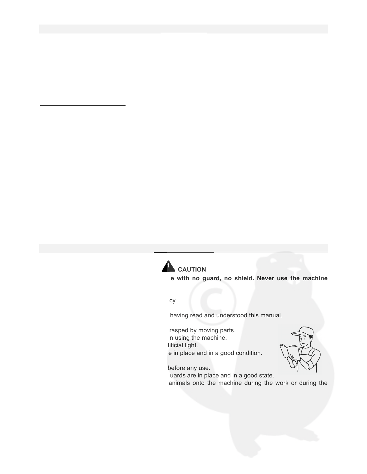
CAUTION
Some of the illustrations show the machine with no guard, no shield. Never use the machine
without these devices.
• Learn to stop the machine in case emergency.
• Read this manual.
• Do not let anybody use the machine before having read and understood this manual.
• Do not let children use the machine.
• Do not wear loose clothes. They might be grasped by moving parts.
• Always wear protection equipments for when using the machine.
• Only work during daylight or with a good artificial light.
• Check that the safety instruction stickers are in place and in a good condition.
• Keep the machine free from debris or mud.
• Check that the machine can work properly before any use.
• Check that all the shields, grids and safety guards are in place and in a good state.
• It is strictly forbidden to carry persons or animals onto the machine during the work or during the
transportation.

© SAT – 09/2006
5
• Never stop or start roughly when working on a slope. Never use the machine to work on a stepping
terrain.
• Reduce the ground speed when driving on a slope and when turning straight
in order to prevent from any risk of losing control.
• Be very careful when bordering ditches.
• Stop the engine, and remove the sparking plug ignition cover before any
intervention on the machine.
• Never work under the machine or its parts when lifted, unless they are
blocked and maintained into position with sufficient security.
• When driving on a slope, always work going up or down but never across the
slope.
• Stay clear of unsteady embankments, holes or rocks. They might be dangerous during work or
transport.
• Keep away from electric wires and obstacles. A contact with electric wires cause electrocution and
death.
• Stop the machine progressively when lifting or lowering the machine.
• When stopping the work, stop the engine and remove the sparking plug ignition cover before leaving
the mower.
• Engage all the safety equipments.
Move the controls only when correctly sat down in the mower
• Visually check hydraulic leaks and if some parts are faulty or missing. Repair before use.
Never change the adjustment of the regulator, it is set in the factory. Unsetting the regulator would cause
failures.
• Ensure that the user of the machine has already read and understood this
manual and that he is aware of all the safety instructions before any use.
• Always use a chuck and bronze hammer when replacing or intervening
on the pins and bolts at the end of rams, rod … etc in order to avoid the
projection of metal fragments.
© SAT – 09/2006
6
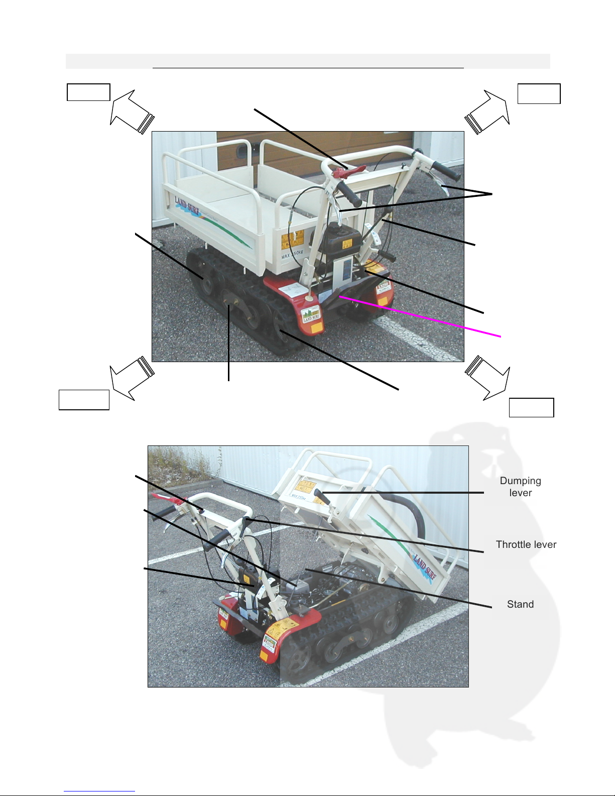
DIFFERENT PARTS OF TRANSPORTER (LS280)
Front
Right
rear
left
Side Clutch
Lever
Travel Lever
Throttle lever
Idle Wheel
Driving Sprocket
Turning Wheel
Recoil Starter
Speed change
Lever
Fuel tank
Exhaust
silencer
Dumping
lever
Stand
On/off engine
switch
Foot Rest
(LS280)
© SAT – 09/2006
7
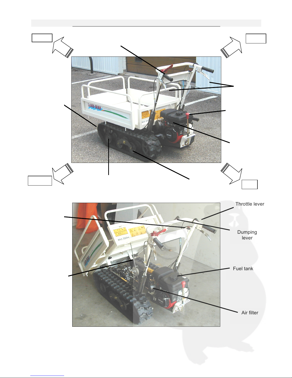
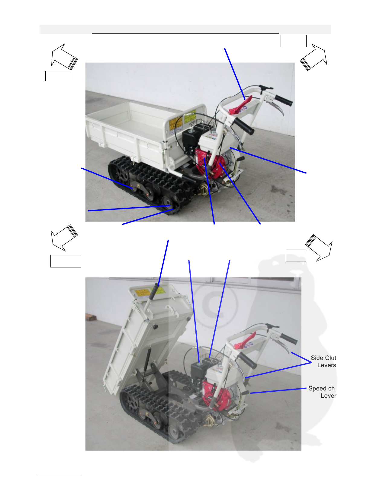
DIFFERENT PARTS OF TRANSPORTER (LS360)
Right
rear
left
Side Clutch
Levers
Travel Lever
Throttle lever
Idle Wheel
Driving Sprocket
Turning Wheel
Recoil Starter
Speed change
Lever
Fuel tank
Air filter
Dumping
lever
Stand
On/off engine
switch
© SAT – 09/2006
8
DIFFERENT PARTS OF TRANSPORTER (LS461)
Front
Right
rear
left
Travel Lever
Throttle lever
Driving Sprocket
Turning Wheel
Recoil Starter
Speed change
Lever
Fuel tank
Air filter
Dumping
lever
On/off engine
switch
Idle Wheel
Side Clutch
Levers
muffler

© SAT – 09/2006
9
SAFETY INSTRUCTION STICKERS
Note their location and replace them immediately in case of damage or when missing
Beware of hot surfaces exhaust gases and burnt read owner’s manual
Before doing maintenance
remove the spark plug
Stand clear of the machine
read owner’s manual
Beware of the rotating parts
under the shield.
Do not load in height
Always use the stand to
secure the folded bucket
・ Always wear protective equipment.
・ Do not opearte in slope more than 20°
・ Always wera safty shoes during the operation
Do not change of gear on slopes
Pay Attention for Backgear
(only LS280)
Do not Ride on the Sloop operation

© SAT – 09/2006
10
CONTROLS
Travel lever(A, figure1)
This lever transmits the power
from the engine to the
transmission. Grip the lever with
the handlebar and it will be in
"driving" position. Release the
handlebar and it will be in "stop"
position.
The driving clutch lever is
connected with the brake. When
the lever is in "stop" position, the
parking brake is led to "on"
condition.
WARNING
Do not fix the driving clutch lever with wires or strings or straps, which is very dangerous.
.
Speed lever (F, figure1)
This lever decides the speed of the machine. There are two steps for driving forward ("1" & ‘'2") and one
step for driving backward ("R'). Before changing speed, shift the driving clutch lever to "stop" position and
stop the machine.
WARNING
Only allowed to change travel speed when machine is stopped.
Side Clutch Lever (C, figure1)
It is to change directions of the machine. Grip either lever and the machine turns to that direction. When
you grip both levers at the same time, the machine stops on the spot.
WARNING
Handle the side clutch lever with a low speed, or the machine will turn fast, which is very
dangerous.
ON/OFF engine switch (D, figure 1)
Turn the switch « ON » to start the engine. Turn the switch « OFF » to
stop the engine.
Dumping Lever (G, figure 1)
It is necessary when the platform is dumping. Grip the lever and pull it
up.
Choke lever (E figure 1)
Pull the choke knob to start the engine when it is cold. Push the knob
when the engine has started.
Throttle lever
(Figure 3)
It is to adjust the rotation of the engine.
Figure 1
Figure 3
G
 Loading...