

Ordan TDDFM14, TDFM44 Owner's Manual

www.maxitrol.com
© 2003, Maxitrol Company, 23555 Telegraph Rd., Southfield, MI 48037 Form TDFM 11/03

ERRATIC DISPLAY
THERMOSTAT READS HI, LO
PERMANENTLY
1)
Press the reset button once with a small pin
and hold in for two seconds. Then reprogram.
1)
Replace unit.
Table of Content s
Installation
Operation (Programming)
Features
System Selector Switches
Connecting Wires and Mounting Thermostat
Programming/Setting Clock
Personal Program Schedule
Reviewing Program Settings
Manual Override
3
6
10
10
12
15
21
22
Backlighting
Trouble Shooting Guide
Wiring Diagrams 27
25
26
25
Other Features
Backlighting
LIGHT
Press
The display will remain backlit for
IMPORTANT
1
Read the entire installation section of
this Owner’s Manual thoroughly before
you begin to install or operate your Maxitrol
Thermostat.
Remove the mylar label from the display
window.
INSTALLATION
2
All installation is normally performed at
your thermostat.
PROGRAMMING
3
You can practice programming before
installing your thermostat by inserting
and connecting the batteries and following
the instructions on page 10.
OPERATION
4
Y our Maxitrol Selector is designed to
operate with DFM/DFME 14 systems only .
TEMPERATURE RANGE
5
Y our Selector can be programmed
between 40°F and 150°F (5°C and 65°C).
However, it will display discharge air
temperature from 32°F and 159°F (0°C and
70°C).
BATTERY WARNING
6
When the batteries are low, the “LOW
BATT” indicator on the display will flash.
When this happens, install new batteries
immediately. Once the “LOW BATT”
indicator appears, the thermostat will
continue to operate for approximately 30
days. (Only alkaline batteries should be
used in your thermostat. Rechargeable
batteries have different properties which
may cause the thermostat to not operate
properly. Do not use old batteries.) The
batteries should last one year.
4
Read This Before Inst alling Thermost at

disappear if you were in
(*From temporary or permanent manual
override state)
NOTE: You can also return the current
program by pressing “HOLD TEMP”
once in permanent override mode.
permanent manual override.
CAUTION: The batteries are the only source of power used to
operate your thermostat. If you do not replace the batteries, the
display will dim and your system will operate on the last
programmed temperature or the factory default.
5
NOTE: If you plan to be away from the premises more than 30
days, we recommend that you replace the old batteries with new
alkaline batteries prior to leaving.
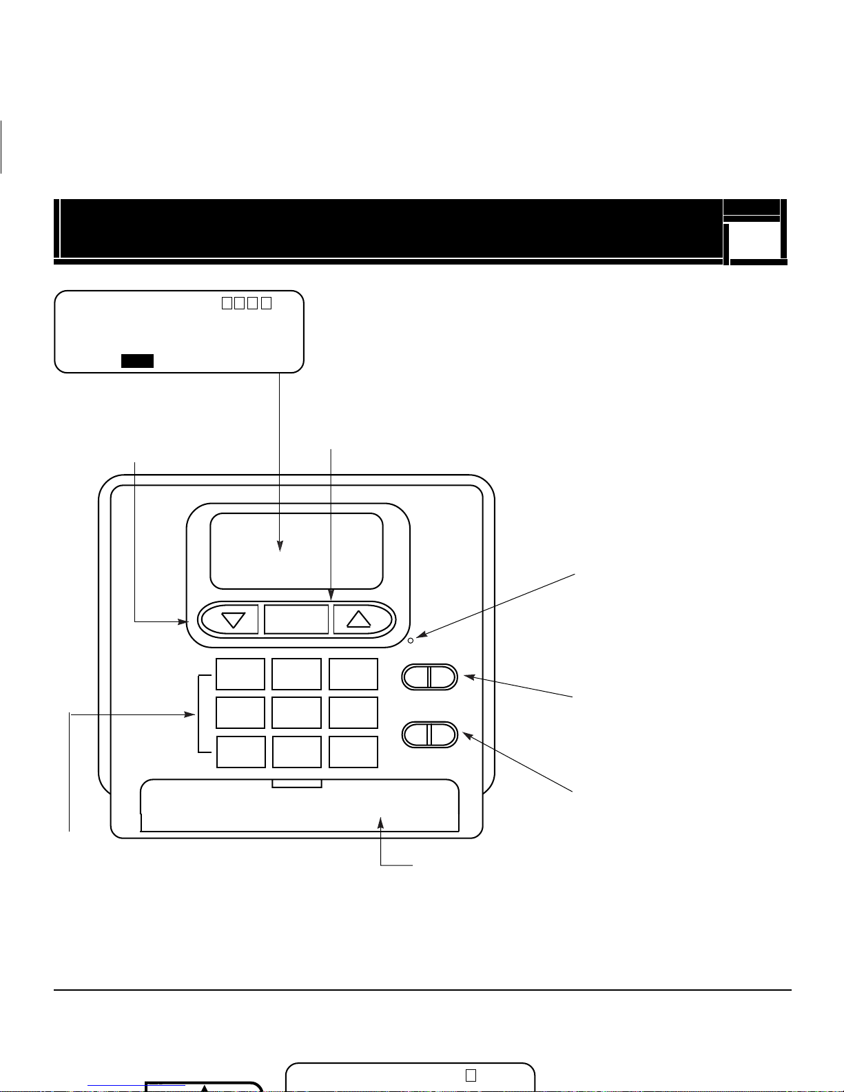
Features
M T W TH F SA SU
AM
PM
88:88 88
LO BAT
Individual
pushbuttons for
raising or lowering
temperature settings.
SET
TEMP
6
1
2
4
3
Display shows time, day, temperature, program number,
C
hold, usage and low battery indicator.
HOLD
TEMP
Display backlight for viewing in the dark.
Reset button for resetting
computer back to
LIGHT
1 OFF 2
12:00A.M. and clearing all
programs.
Soft touch programming
buttons (see below)
Temporary Manual Override
In the following example, the present room temperature is 60°F and we want to raise the
temperature to 70°F temporarily until the next program.
F C
Customer Auxiliary Switch
Manual switches for F°/C°
Battery door for easy access.
Manual switches
2
Press arrow to display
23
Program:
Press and hold
to raise
temperature.
The new temperature will hold until the next program time is reached.
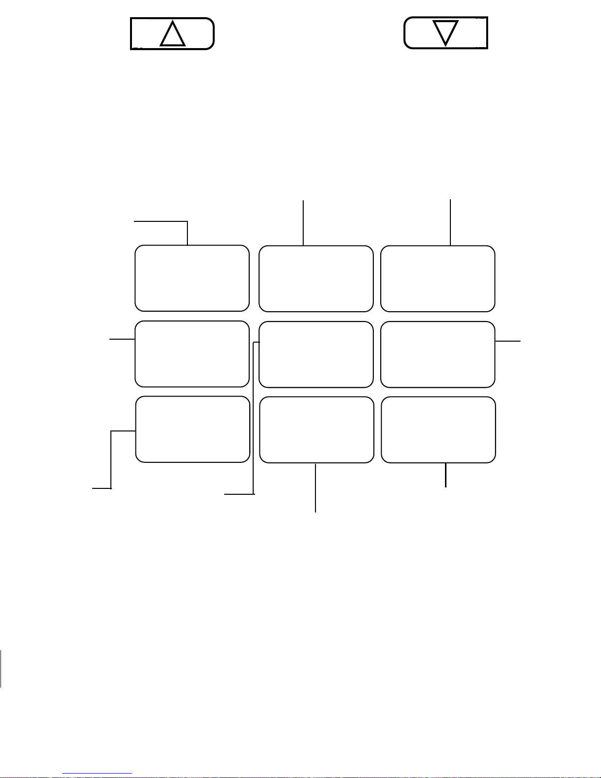
For entering minute of day.
For entering
hour of day.
Press and hold
to lower
temperature.
For entering day of week.
HOUR MIN
7
DAY
For reviewing
and changing
weekday or
weekend
programs
Picks the
day/days
for
programs
PROG
PROG
DAY
Automatically
programs thermostat
for weekday and
weekend program
settings.
AUT O
12/24 HRS
PROGRAM
HOLD/
RETURN
CLEAR
Provides permanent
temperature setting by
overriding stored programs.
Also, clears manual override
and returns to current program.
Changes
the clock
into 12 or
24 hour
(military)
mode.
Returns display
to current time
and temperature.
Installation
What You Need
This thermostat comes with two #8 slotted screws and two wall anchors for mounting. To
install your unit, you should have the following tools and materials.
Small slotted screwdriver
Hammer
Electric drill and 3/16” bit
Two 1.5V (AA) Size Alkaline batteries
8
Reviewing Programs
You may want to review the programs to see that the settings are correct.
Weekday
Programs
21
SA
:
Normal display of current time,
temperature, and day of week.
through F and SA and SU as same programs. Then, display and change the
programs of only those days which will have different programs.
NOTE: If program time remains 0:00, that particular program will not be
effective; e.g., if Program #2 has time 0:00, the thermostat will jump from
Program #1 to Program #3.
9
Mount Wallplate & Thermostat
Snap open the wallplate from your thermostat by pressing the release tab on the bottom of
the thermostat.
Position wallplate on wall and pull wire with RJ45 connector and any additional wires through
large opening. Then level for appearance. Mark holes for plastic anchors provided.
Drill holes with 3/16” bit and gently tap anchors into the holes until flush with wall.
Reposition wallplate to wall, pulling wires through large opening. Insert mounting screws
provided into wall anchor and tighten. (See Figure 1.)
1
2
3
4
5
Figure 1
Installation
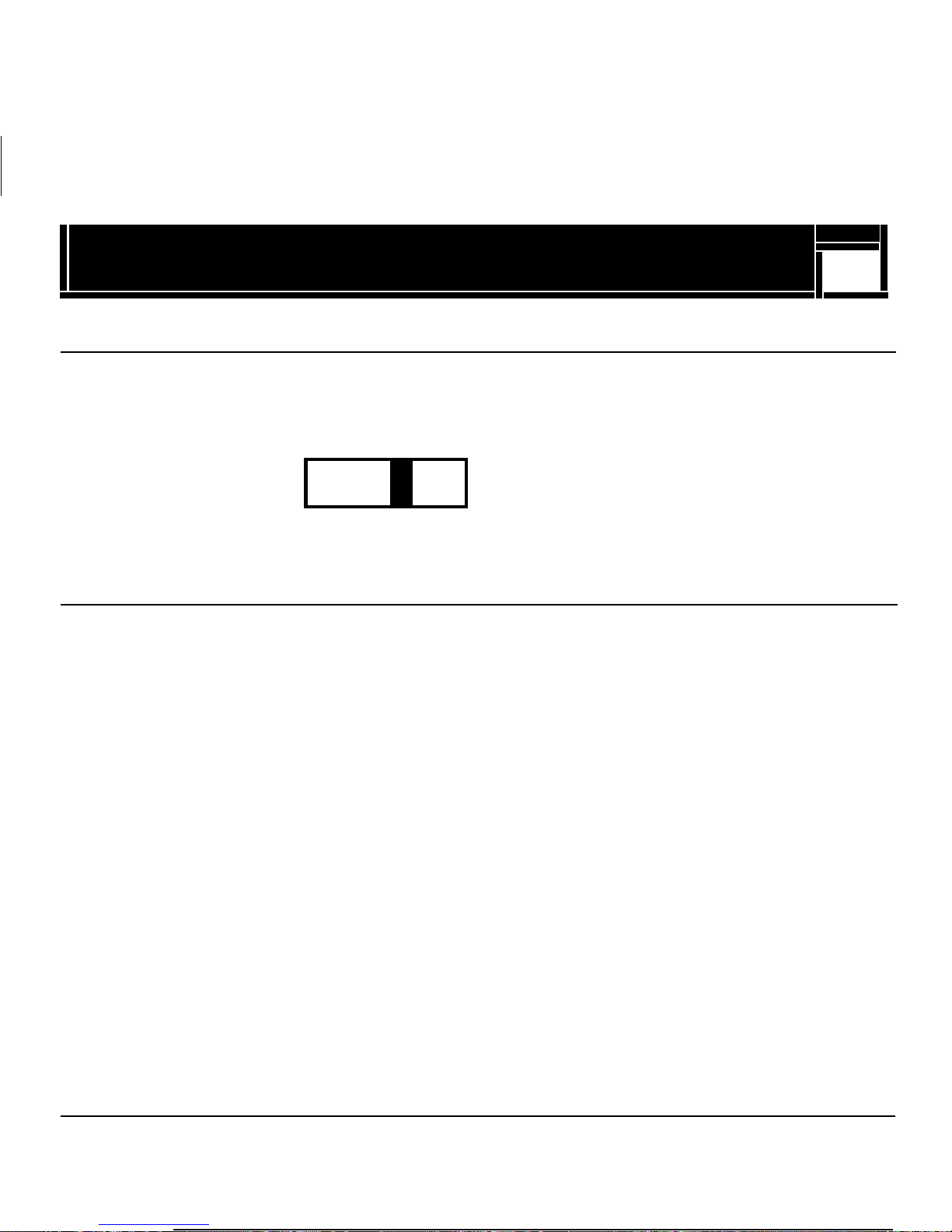
Selector Switches
The °F/°C selector switch is located on the front.
°F/°C selector (Fahrenheit/Centigrade)
Your thermostat is set for °F mode from the factory. In order to change to °C mode,
slide the switch to °C.
10
F
C
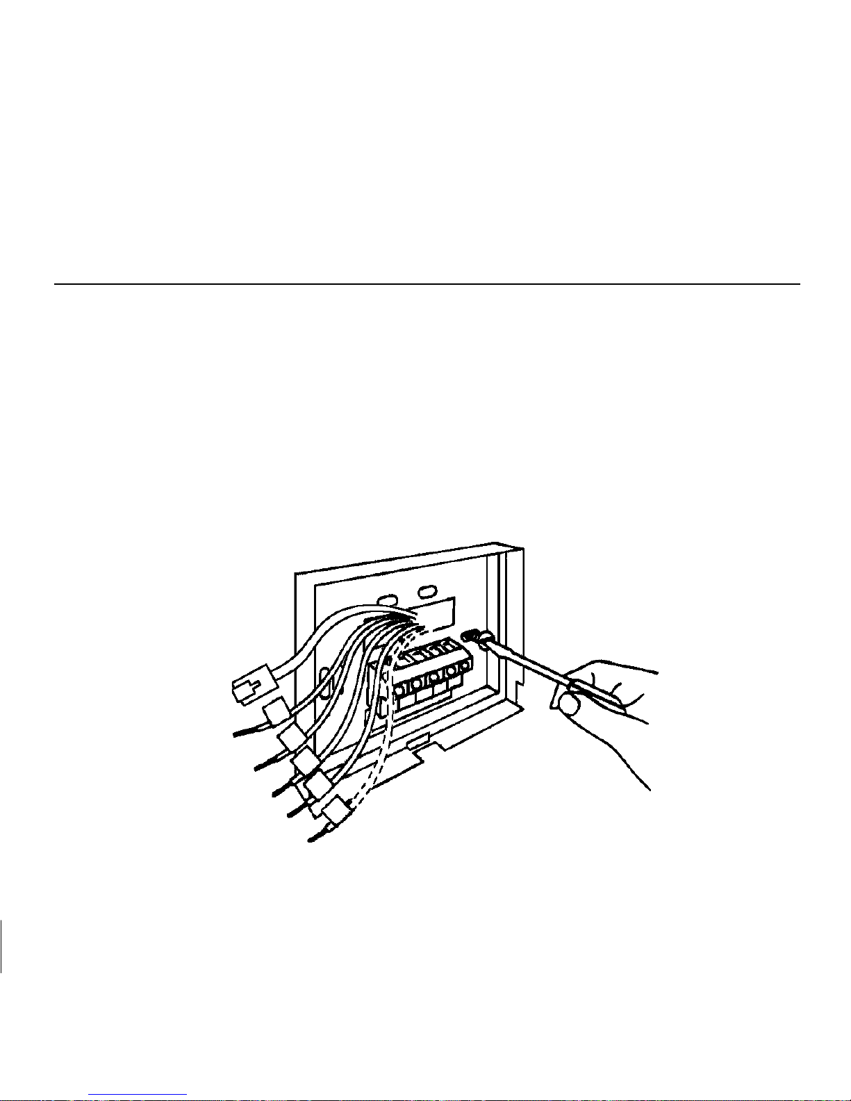
Connect Wires & Mount Thermostat Cover to Wall Plate
Insert RJ45 Connector.
If remote temperature sensor is used: remove existing RTD Sensor from Terminals 1 & 2 and
replace with remote temperature sensor wires.
Be sure to tighten the terminal screws securely, otherwise a loose wire could cause
operational problems with your system or thermostat.
Push excess wire back into hole to prevent interference with mounting of the thermostat cover.
Customer Choice switches are accessed through terminals 3, 4 & 5. Switch #1 is accessed
through terminals 3 & 4. Switch #2 is accessed through terminals 4 & 5, with terminal #4 being
common.
Insert the bottom tab on the thermostat body into the slot at the bottom of the wallplate. Press
top of the thermostat body to snap it into the wallplate. (NOTE: Do not force the thermostat
onto the wallplate, as the terminal pins may be damaged. If it does not snap properly,
the thermostat may not work.)
Insert the two AA size batteries, observing the polarity marked on the unit.
Individual Day Programming
To program for each individual day separately by a different set of programs, first select day
by displaying the day of program, then insert the desired times and temperatures.
Press
Display Reads
19
 Loading...