

ORD RoVa3D User Manual

User Manual
Rev. A

User Manual
orddistribution.com Copyright 2015 ORD Solutions (Dist.) Inc. Page 2
Table of Contents
1. Getting to know your RoVa3D printer ..................................................................... 5
1.1. What’s in the box .................................................................................................................. 5
1.2. Specification ......................................................................................................................... 6
1.3. What is 3D Printing? ............................................................................................................. 7
1.4. RoVa3D Overview ................................................................................................................. 8
1.4.1. Component Names - Front .......................................................................................... 8
1.4.2. Component Names - Back ........................................................................................... 9
2. Getting Started .................................................................................................. 10
2.1. Safety .................................................................................................................................. 10
2.2. 3D Printing: From Idea to Print ........................................................................................... 11
2.3. Initial setup ......................................................................................................................... 12
2.3.1. Tools you will need .................................................................................................... 12
2.3.2. Connecting the Power Supply .................................................................................... 13
2.3.3. Installing Filament Guide Tubes ................................................................................. 13
2.3.4. Installing Filament Feed Tubes .................................................................................. 14
2.3.5. Installing Extruder Springs ......................................................................................... 14
2.3.6. Installing Filament Spool Holders .............................................................................. 15
2.3.7. Loading Filament ........................................................................................................ 15
2.3.8. Connecting the RoVa3D to your Computer ............................................................... 19
2.3.9. Installing the USB Drivers ........................................................................................... 19
2.3.10. Installing Pronterface / Printrun .................................................................................. 20
2.3.11. Testing Pronterface communication with the RoVa3D ............................................... 21
2.3.12. Installing Slic3r ........................................................................................................... 23
2.3.13. Disabling Windows Update ........................................................................................ 24
2.3.14. Testing the Homing Switches ..................................................................................... 25
2.3.15. Taping the Print Bed .................................................................................................. 29
2.3.16. Leveling the Print Bed ................................................................................................ 32
2.3.17. Leveling Nozzles ......................................................................................................... 37
2.3.18. Setting Z Home .......................................................................................................... 38
2.3.19. Safety Enclosure ......................................................................................................... 40

User Manual
orddistribution.com Copyright 2015 ORD Solutions (Dist.) Inc. Page 3
2.4. Basic usage ......................................................................................................................... 46
2.4.1. Choosing a 3D Model ................................................................................................ 46
2.4.2. Slicing Your Model ..................................................................................................... 46
2.4.3. Before Printing ........................................................................................................... 47
2.4.4. Printing Your Model ................................................................................................... 48
2.4.5. Cool-down .................................................................................................................. 48
2.4.6. Removing Your Model ................................................................................................ 48
2.4.7. Print Examples ............................................................................................................ 48
3. Advanced Usage ................................................................................................. 49
3.1. Multi-Material Printing ........................................................................................................ 49
3.1.1. Changing material types ............................................................................................ 49
3.1.2. Ooze prevention ........................................................................................................ 51
3.1.3. Calculating nozzle offsets ........................................................................................... 51
3.1.4. Designing Multi-Material Models ............................................................................... 53
3.1.5. Creating AMF Files ..................................................................................................... 58
3.2. Additional RoVa3D Functionality ........................................................................................ 60
3.2.1. Turn LED lights on/off ................................................................................................ 60
3.2.2. Avoid Crossing perimeters ......................................................................................... 60
3.2.3. Vase mode ................................................................................................................. 61
3.2.4. Print bed cover material tips ...................................................................................... 61
3.2.5. Measuring filament diameter ..................................................................................... 62
3.3. Pushing the limits ................................................................................................................ 64
3.3.1. Auto PID ..................................................................................................................... 64
3.3.2. Extruder steps per mm ............................................................................................... 66
3.3.3. Advanced Slic3r settings ............................................................................................ 68
4. Keeping things running smoothly ......................................................................... 73
4.1. Recommended Service Schedule ....................................................................................... 73
4.2. Level 1 Service .................................................................................................................... 74
4.2.1. Multipoint inspection ................................................................................................. 74
4.2.2. Clean the nozzles ....................................................................................................... 74
4.2.3. Clean the filament feed gear teeth ............................................................................ 76

User Manual
orddistribution.com Copyright 2015 ORD Solutions (Dist.) Inc. Page 4
4.2.4. Service the filament feed tube ends .......................................................................... 77
4.2.5. Oil Bearings ................................................................................................................ 78
4.2.6. Oil smooth shafts ....................................................................................................... 79
4.2.7. Oil Leadscrews ........................................................................................................... 81
4.2.8. Adjust belt tension ..................................................................................................... 82
4.2.9. Update the firmware .................................................................................................. 83
4.3. Level 2 Service .................................................................................................................... 85
4.3.1. Refresh bed printing surface ...................................................................................... 85
4.3.2. Change nozzles .......................................................................................................... 85
4.3.3. Replace Belts .............................................................................................................. 86
4.3.4. Clean fans ................................................................................................................... 89
4.3.5. Service the smooth shafts .......................................................................................... 90
4.4. Level 3 Service .................................................................................................................... 91
4.4.1. Replace Ball Bearings ................................................................................................. 91
4.4.2. Replace Linear Bearings ............................................................................................. 93
4.4.3. Replace filament feed tube ........................................................................................ 95
4.4.4. Replace liquid coolant ................................................................................................ 95
4.5. Level 4 Service .................................................................................................................... 98
4.5.1. Replace hot-end heater cartridge .............................................................................. 98
4.5.2. Replace print bed heating element ............................................................................ 99
4.5.3. Replace the smooth shafts ....................................................................................... 100
5. Troubleshooting ............................................................................................... 102
5.1. First layer won’t stick ........................................................................................................ 103
5.2. Cleaning extruder filament drive wheel ............................................................................ 105
5.3. Clearing Extruder filament guide holes ............................................................................ 105
5.4. Clearing a Jammed Hotend ............................................................................................. 106
5.5. Clearing a jammed nozzle ................................................................................................ 106
5.6. Repairing a popped filament feed tube ........................................................................... 107
5.7. Printer won’t home X/Y/Z ................................................................................................. 107
5.8. Bed won’t heat above X(°C) ............................................................................................. 108
5.9. Nozzle won’t heat above X(°C) ......................................................................................... 109

User Manual
orddistribution.com Copyright 2015 ORD Solutions (Dist.) Inc. Page 5
5.10. Feedtube end broken off inside quick release ................................................................. 110
5.11. If all else fails ..................................................................................................................... 110
Special thanks to Tim Hedstrom, Joan Touzet, and all of our forum users and Kickstarter
backers who have contributed to the body of knowledge incorporated into this manual!
1. Getting to know your RoVa3D printer
1.1. What’s in the box
List of items:
• RoVa3D printer
• 1 power supply with power cord
• 24” filament feed tubes (one per extruder, one spare)
• 4” inch long filament guide tubes (one per extruder)
• USB cable
• Spool holders
• Extruder tension screws with springs
• Filament cleaning wraps
• Spare quick connects (one male, one female)
Optional items:
• Spare nozzles (0.35mm, 0.5mm, 0.7mm)
• Maintenance kit
• Roll of polyimide (Kapton) tape
• Filament spools
VIDEO
Confirm the contents of your printer box:
http://www.orddistribution.com/videos/rova3d
-r1/printer-box-contents

User Manual
orddistribution.com Copyright 2015 ORD Solutions (Dist.) Inc. Page 6
1.2. Specification
Printing technology: FDM (Fused Deposition Modeling) / FFF (Fused Filament Fabrication)
Print area size: 284 W x 301 L x 191 H mm (11.18” W x 11.88” L 7.55” H)
Build volume: Up to print area size, depending on multi- nozzle configuration
Layer height: Min 25 microns (0.0009”), Max 1000 microns(0.039”)
Print resolution: X: 5 microns (0.0002”)
Y: 5 microns (0.0002”)
Z: 0.25 microns (0.00001”)
Filament Diameter: 1.75mm (0.069”)
Nozzle Diameter: Available 0.35, 0.5, 0.7, 1.0 mm (0.014”, 0.020”, 0.028”, 0.039”)
Footprint: 280 W x 381 L mm (11” W x 15” L)
Overall Dimensions: 665 W x 430 L x 680 H mm (26.18” W x 16.93” L x 26.77” H)
Weight: 18.1kg (40 lbs)
Shipping box: 711 W x 508 L x 660 H mm (28” W x 20” L x 26” H)
Shipping Weight: 24kg (53lbs) without extra items
Electrical:
Power Supply Input: 115/240VAC, 10A/6A, 50/60Hz
Printer Input: 12VDC, 50A (max).
Mechanical: Anodized Aluminum, Stainless Steel, Injection Molded ABS Plastic
Temperature limits:
Operational: 15°C to 30°C, 10-90% RH (non-condensing)
Storage: -10°C to 40°C, 5-95%RH (non-condensing)
Stepper motors: NEMA 17 1.8˚ Step with 1/32
nd
micro stepping
Optional “Cool Muscle” Ultra-High-Performance Drive Motors with Closed Loop Vector
Control

User Manual
orddistribution.com Copyright 2015 ORD Solutions (Dist.) Inc. Page 7
1.3. What is 3D Printing?
3D printing (or additive manufacturing, AM) is any of various processes to make a three-dimensional
object.
[1]
In 3D printing, additive processes are used, in which successive layers of material are laid down under
computer control.
[2]
These objects can be of almost any shape or geometry, and are produced from a 3D model
or other electronic data source. A 3D printer is a type of industrial robot.
The RoVa3D uses a technology called (FDM) Fused deposition modeling. FDM is an additive
manufacturing technology commonly used for modeling, prototyping, and production applications. It is one of
the techniques used for 3D printing.
FDM works on an "additive" principle by laying down material in layers; a plastic filament or metal wire is
unwound from a coil and supplies material to produce a part.
Fused deposition modeling:
1. Nozzle ejecting molten plastic
2. Deposited material (modeled part)
3. Controlled movable table
Image created by Zureks, used under the GNU Free Documentation License http://commons.wikimedia.org/wiki/File:FDM_by_Zureks.png
VIDEO
How 3D Printing Works:
http://www.orddistribution.com/videos/rova3d
r1/how-3D-printing-works

User Manual
orddistribution.com Copyright 2015 ORD Solutions (Dist.) Inc. Page 8
1.4. RoVa3D Overview
1.4.1. Component Names - Front

User Manual
orddistribution.com Copyright 2015 ORD Solutions (Dist.) Inc. Page 9
1.4.2. Component Names - Back

User Manual
orddistribution.com Copyright 2015 ORD Solutions (Dist.) Inc. Page 10
2. Getting Started
2.1. Safety
High Temperatures
Warning: The RoVa3D generates high temperatures at the print head and print surface. Never reach into the
print area while the printer is in operation. Always allow the printer to cool down before reaching inside. Keep
combustible or flammable materials away from the print head and the print surface.
Pinch Points
Warning: The RoVa3D includes moving parts that can cause injury. While printing, the extruder gears, print
head, and print bed (forwards and back, as well as up and down) will be in motion. Keep hands, clothing, hair,
jewelry, and any loose articles clear of moving parts when the printer is on, and ensure that there are no items
below the print bed that will interfere when the bed lowers during printing.
Fans and Cooling
Caution: Before powering on the printer, verify that the fans on the power supply, cooling system, and
electrical enclosure are free of obstructions and debris. The RoVa3D will automatically turn on the cooling fans
and coolant pump once the coolant temperature is greater than 40°C. After a print is finished, ensure that the
printer remains powered until all of the hot ends have cooled to below 50°C. Failure to ensure proper cool
down can result in hot end jamming due to filament swelling.
Ventilation
Caution: During its operation the RoVa3D melts plastic, which can release odors. Ensure the printer is
operated in a well-ventilated area. On initial heat-up there may be a small amount of smoke from the nozzles
due to oil residue from manufacture. This is normal, and should cease within 30 minutes.
Electrical
Caution: Maintain easy and clear access to electrical connections, and do not overload electrical supplies. In
case of emergency, disconnect the RoVa3D power supply from the wall socket.
Lifting
Caution: The RoVa3D weighs 40 pounds. Use caution when lifting, and lift with two people if necessary.
Always lift by holding the aluminum side panels, or by gripping the threaded rods under the top panel. Never
lift directly by the extruder assemblies, aluminum top panel, spool holders, control board case, bed assembly,
print head assembly, or x-axis guide rails.
User Manual
orddistribution.com Copyright 2015 ORD Solutions (Dist.) Inc. Page 11
Safety Enclosure
Caution: To meet safety regulations, the printer must be operated with the safety enclosure installed. See
Safety Enclosure section for assembly instructions.
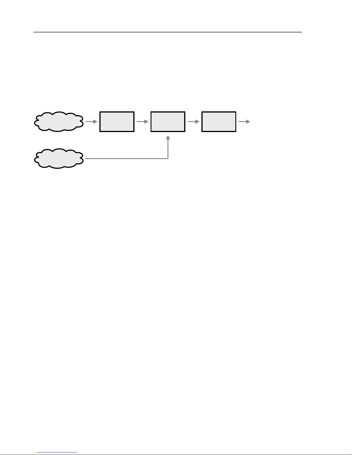
2.2. 3D Printing: From Idea to Print
3D#Idea Design#Software Slicing#Software Interface#Software
Existing#Design
3D Idea: The process starts with an idea for a 3D object to print. This part is up to you, and it can be anything
from a Yoda head to a part for your new supercar design.
Design Software: This is where you create a 3D drawing of your idea. There are many different software
options available for designing, both open-source and proprietary. These software packages are often referred
to as CAD (Computer-aided Design) software. The output of this software will usually be an .stl file when being
used for 3D printing.
A popular design software package is Sketchup Make, which is free to use for non-commercial work. Popular
commercial software includes SolidWorks and AutoCAD.
Existing Design: If you just want to start printing with an existing design, there are thousands of designs
available at repository sites, such as thingiverse.com, cubehero.com, and youmagine.com.
Slicing Software: Once you have a 3D design (.stl file), it needs to be turned into a machine-friendly file that
the printer can understand, called G-code (.gcode file). The slicing software will separate the design into many
horizontal layers, which the printer can print one at a time, along with other information such as nozzle and print
bed temperatures. This part of the process, along with the interface software and printer firmware, is often
referred to as CAM (Computer-Aided Manufacturing).
The base configuration files for your ORD printer are designed to be used by a slicing program called Slic3r. If
you are new to printing, we recommend that you start with Slic3r (so you can use the base settings we provide),
but once your understanding grows, you could try alternative open-source slicing programs such as Cura, or
proprietary programs like Simplify3D.
Interface Software: The interface software will send the G-code to the printer over the USB connection. The
interface software also allows you to manually control the printer; you can move the print head and bed,
extrude filament, and set temperatures.

User Manual
orddistribution.com Copyright 2015 ORD Solutions (Dist.) Inc. Page 12
The default interface software for your ORD printer is called Pronterface, which is part of an open-source suite
called Printrun. There are other interface software packages you can try once you are familiar with Pronterface,
or if you use Simplify3D for slicing, it also has built-in interface software.
3D Printing: Once you have setup your printer, and loaded the filament, you can start the print from the
interface software. When the printer receives the G-code over the USB connection, the built-in printer firmware
will interpret the instructions and send the correct signals to the motors to create your print.
2.3. Initial setup
2.3.1. Tools you will need
The following are tools you might need to use during the setup or operation of your printer. The items under
Maintenance Kit are provided with your printer if you purchased a printer package, or the optional Maintenance
Kit.
Maintenance Kit
• Drill Bits: Including micro-bits, these are used for cleaning the nozzles and extruders.
• Polyimide (Kapton) tape: This is used to cover the bed for enhanced part adhesion.
• Hex Wrenches: Used for adjusting various components during set-up.
• 10mm Wrench: To adjust the height of the feed tubes and nozzles.
• Nut Driver: To adjust various nuts, including the bed-leveling nuts.
• Digital Caliper: For measuring filament width, printed parts, and parts to be replicated.
• Feeler Gauges: Used to adjust the nozzle heights.
• Razor Blade Scraper: Used to remove printed parts from the bed, and to trim the polyimide tape.
• Side cutters: For trimming filament.
• Infrared Thermometer: To ensure your heat settings are calibrated.
Additional Tools
• Long nose pliers or tweezers: These are useful to reach under the print heat and remove melted
filament, while keeping your fingers at a safe distance.
• Hobby knife (Exacto or similar): Useful for cleaning up printed items, or scraping melted filament off the
nozzles.
• Scotch-Brite pad: Used for cleaning extruder drive wheels and nozzle tips.
• 100% Acetone: Used for cleaning the print bed and polyimide tape before printing. Available at paint
or hardware stores. Warning: Follow all safety instructions included with the acetone.
• Paper towels: For cleaning the bed with acetone.
• Decal squeegee or credit card (old, inactive, or promotional): This can be used this to apply the
polyimide tape.
• Protective safety gloves: These will protect your hands while working on the nozzles and print bed.
• ¾” Deep Socket (or similar size): This can be used to level the bed and calibrate the nozzle heights.
• 17mm or adjustable wrench: To hold the heater blocks when replacing nozzles.

User Manual
orddistribution.com Copyright 2015 ORD Solutions (Dist.) Inc. Page 13
2.3.2. Connecting the Power Supply
1. Connect the power supply to the printer with the two 6-pin connectors and one 4 pin connector. The
small 2-pin connector is unused.
2. Connect the power supply to a wall socket with the supplied power cable.
2.3.3. Installing Filament Guide Tubes
Slide the 4 inch filament tube into the bottom side of each extruder. These tubes will help guide the filament
from the spool to the extruder.
User Manual
orddistribution.com Copyright 2015 ORD Solutions (Dist.) Inc. Page 14
2.3.4. Installing Filament Feed Tubes
Connect the 24 inch filament tubes. The tubes are installed in the quick connects by pressing the tube into the
connector. The fit can be verified by gently pulling up on the tube after it is installed. Each tube will connect
from an extruder to the nozzle quick connect with the corresponding number.
To remove the filament feed tubes, press down on the blue ring, press the filament feed tubes down gently,
then pull them up and out of the quick release.
2.3.5. Installing Extruder Springs
Install the extruder tension screws with spring and screw head on the same side as the motor, and the nut on
the pressure door. Gently press in the bolt head, while holding the extruder door closed, to compress the
spring slightly. This will allow you to easily tighten the nut. The nut should be tightened until the spring has
approximately 1mm in between each coil. This should leave approximately 10mm of thread protruding beyond
the nut.
VIDEO
Installing filament feed tubes:
http://www.orddistribution.com/videos/rova3dr1/installing-filament-tubes
User Manual
orddistribution.com Copyright 2015 ORD Solutions (Dist.) Inc. Page 15
2.3.6. Installing Filament Spool Holders
Install the spool holders on the side of the printer by threading each holder into the appropriate hole on the
chassis. As shown in the pictures below, two spool holders are installed on the side of the printer below the
control box, and three holders are installed on the opposite side of the printer. The jam nut is to remain on the
holder before it is threaded into the chassis.
2.3.7. Loading Filament
1. Place a spool of filament onto a spool holder.
2. On each extruder to have filament installed, remove the tension on the extruder door bolts: Gently
press the extruder bolts into the springs, while holding the extruder door, and loosen the nuts until the
tension is completely removed.
3. Straighten the end of the filament to be installed by gently bending it until it is relatively straight.

User Manual
orddistribution.com Copyright 2015 ORD Solutions (Dist.) Inc. Page 16
4. Insert the free end of the filament into the filament guide tube, and up into the extruder. It may be
necessary to twist the filament slightly while pushing gently.
5. If you are unable to feed the filament by hand up through the extruder into the filament feed tube,
remove the extruder bolt nuts, and open the extruder door. This will allow you to guide the filament
into the upper extruder hole past the extruder gear.

User Manual
orddistribution.com Copyright 2015 ORD Solutions (Dist.) Inc. Page 17
6. Push the filament through the feed tube
7. Push the feed tube into the quick fitting on the top of the extruder body
8. Guide the filament into the hotend

User Manual
orddistribution.com Copyright 2015 ORD Solutions (Dist.) Inc. Page 18
9. Press the feed tube into the hotend quick fitting
10. Replace the extruder pressure bolt nuts and tighten
11. Tie a filament cleaning cloth around the filament where it enters the filament guide tube. This will wipe
the dust and debris from the filament before it enters the tube.
User Manual
orddistribution.com Copyright 2015 ORD Solutions (Dist.) Inc. Page 19
2.3.8. Connecting the RoVa3D to your Computer
1. Plug the supplied USB cable into the USB port on the front of the electronic box.
2. Plug the other end into a free USB port on the tablet or the computer that will run the printing
software.
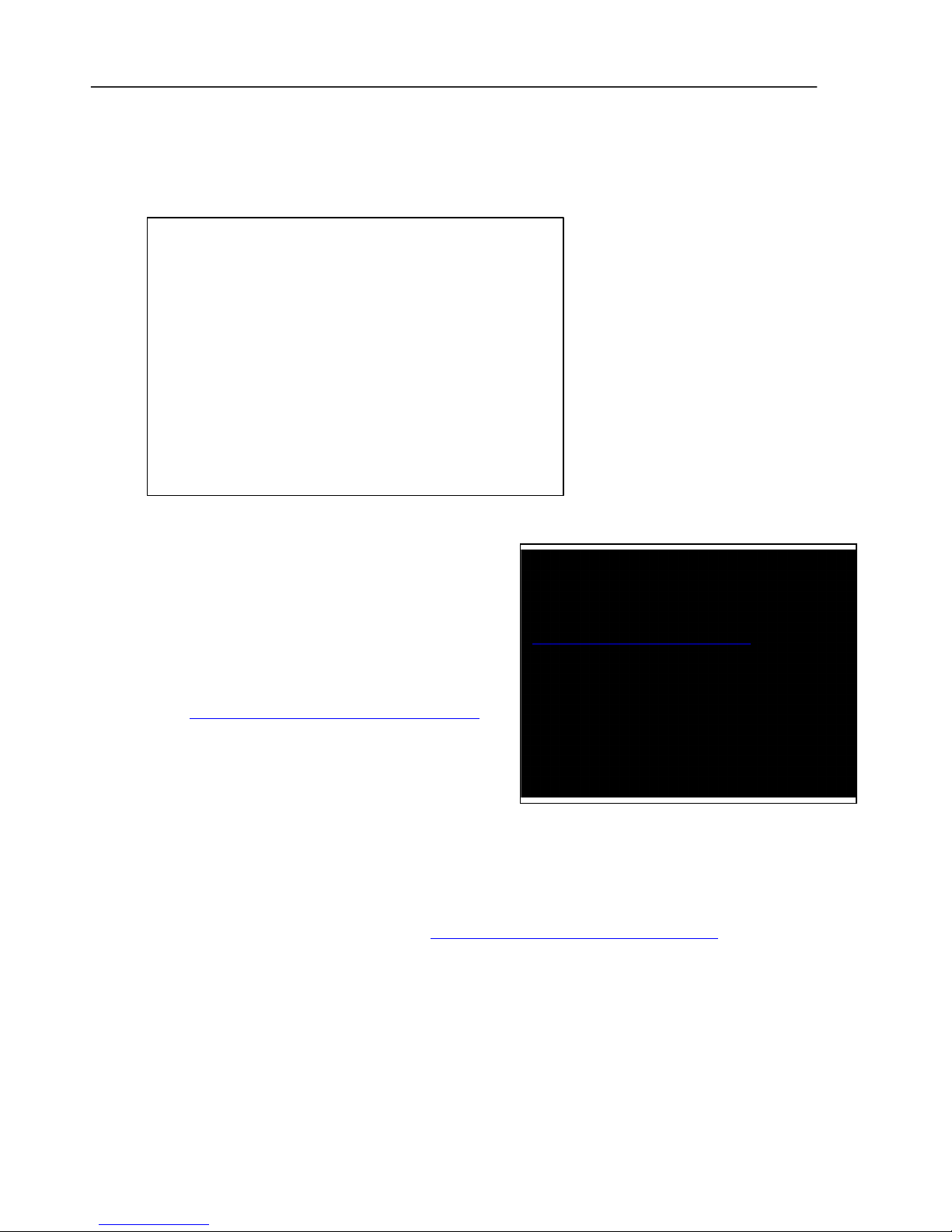
2.3.9. Installing the USB Drivers
The USB drivers are required to allow the computer to
communicate with the RoVa3D.
If the drivers were auto-installed (Windows 7 or 8) when you
connected the USB cable, then you can skip this section.
1. Go to http://www.ftdichip.com/Drivers/VCP.htm
2. Scroll down the page until you see a table.
3. Choose your operating system and the correct
processor architecture. If you don't know your
architecture you can look it up:
a. Windows: Click the Start button, right click on Computer, and click Properties. The processor
architecture (32-bit or 64-bit) is listed under System: System type.
b. Mac: Click the Apple symbol at the top left of the screen and click About This Mac. Open the
Hardware section to locate the Processor Name. Look up your processor in this table to
determine if it is 32-bit or 64-bit: https://support.apple.com/en-ca/HT3696
4. Download and run the appropriate driver version, based on your processor determined above. You
may need to be logged on as administrator.
5. Follow the steps in the installer, and reboot your machine.
NOTE:
All the software and configuration files referred
to in this manual may also be found at:
www.orddistribution.com/software
If your printer came with a USB key, it will
contain all the software and configuration files.
If your printer came with a tablet then all the
software was installed at the factory, and you may
skip the software installation steps.

User Manual
orddistribution.com Copyright 2015 ORD Solutions (Dist.) Inc. Page 20
2.3.10. Installing Pronterface / Printrun
Pronterface is the program that will provide the interface to your printer.
1. Go to http://koti.kapsi.fi/~kliment/printrun/
2. Download the newest .zip file for Mac or Windows.
3. There is no installer program for Pronterface. Extract the files into C:\Program Files\ and create a
shortcut to pronterface.exe on your desktop.
4. Copy the preset file ‘printrunconf.ini’ from the USB drive to C:\Users\<YourUserName>
Ensure Pronterface is not running when you copy this file.

User Manual
orddistribution.com Copyright 2015 ORD Solutions (Dist.) Inc. Page 21
2.3.11. Testing Pronterface communication with the RoVa3D
Pronterface Overview – Left Side

User Manual
orddistribution.com Copyright 2015 ORD Solutions (Dist.) Inc. Page 22
Pronterface Overview – Right Side
Testing Communication
1. Open Pronterface using the shortcut. (Printrun is what is shown on Macs)
2. Change the baud rate to 250000
3. Select the Port that the RoVa3D is connected to.
a. Click the Port button to scan for open ports. The RoVa3D will typically be the highest port
number shown.
b. If you are unable to determine which port the RoVa3D is connected to, run Device Manager,
expand Ports, and look for the COM port assigned to the last entry of ‘USB Serial Port’
4. Click the Connect button and wait for it to connect to the RoVa3D. After a successful connection to the
RoVa3D, you will see the firmware settings displayed in the right side window of Pronterface.

User Manual
orddistribution.com Copyright 2015 ORD Solutions (Dist.) Inc. Page 23
2.3.12. Installing Slic3r
1. Move the Slic3r folder from the supplied USB Thumb drive to ‘C:\Program Files\Slic3r’. This folder
contains both Windows and Mac, and 32-bit and 64-bit versions. Additionally, for each computer type,
there are two versions of Slic3r, 1.1.7, and the latest experimental version, which is currently 1.2.9. Both
versions will be required to enable multi-material printing.
a. Slic3r 1.1.7 contains the capability of combining multiple .stl files into an .amf file, which will be
required to print multi-material printing. This is the only task which Slic3r 1.1.7 will be used for.
b. Slic3r 1.2.9 is an ‘Experimental’ release, but contains all the newest features. Use this version
for all tasks except creating .amf files.
2. Move the ‘Slic3r’ folder from the ‘Slic3r config’ folder files to
‘C:\Users\<YourUserName>\AppData\Roaming\Slic3r’
3. Create a shortcut from each slic3r.exe (Both 1.1.7 and 1.2.9, where you copied the files in step 1) to
your desktop. Rename them to show the correct version number.
4. Run Slic3r
5. To access the multi-extruder options, Slic3r needs to be switched to Expert Mode. You will only need
to do this once (for each computer you install Slic3r on). To enable Expert Mode, go to
File/Preferences. Change the Mode from Simple to Expert. Click OK. You will be prompted to close
Slic3r and reopen it for the change to take effect.

User Manual
orddistribution.com Copyright 2015 ORD Solutions (Dist.) Inc. Page 24
2.3.13. Disabling Windows Update
If Windows Automatic Updates initiates during a print, it could cause the prints to fail. To disable Automatic
Updates (for Windows 7), go to:
Control Panel -> Windows Update -> Change Settings -> Select ‘Download updates but let me choose whether
to install them’ .

User Manual
orddistribution.com Copyright 2015 ORD Solutions (Dist.) Inc. Page 25
2.3.14. Testing the Homing Switches
1. Ensure Pronterface is connected to the RoVa3D.
2. Click the ‘Motors off’ button in the top left of Pronterface.
3. Gently push the X carriage to the middle of the RoVa3D.
4. Gently push the Y carriage (print bed) to the middle of the RoVa3D.
5. Press the +Z 10 button until the print bed is low enough that the homing flag is below the sensor

User Manual
orddistribution.com Copyright 2015 ORD Solutions (Dist.) Inc. Page 26
6. Click the button marked ‘Optos’ in Pronterface.
7. Ensure that the response in the Pronterface commands window shows:
Reporting endstop status
x_min: open
y_min: open
z_min: open
8. If any of the reported sensor status show TRIGGERED, contact Support for assistance.
9. Push the X carriage all the way to the left so that the opto flag is in the opto sensor.
10. Push the print bed all the way towards the rear of the printer so that the Y opto flag is in the Y opto
sensor.

User Manual
orddistribution.com Copyright 2015 ORD Solutions (Dist.) Inc. Page 27
11. Pull the entire Z assembly up so that the Z opto tab is in the Z opto sensor.
12. Press the ‘Opto’ button in Pronterface.
13. Ensure that the response in the Pronterface commands window shows:
Reporting endstop status
x_min: triggered
y_min: triggered
z_min: triggered
14. If any of the opto sensors are not triggered please contact support
15. Once the opto sensors are confirmed working, press the ‘Home All axis’ button in Pronterface
16. Confirm that the Bed is within 5mm of the nozzles once its homed
17. If the nozzles are not within 5mm of the print bed when homed:
a. Loosen the Z opto sensor threaded rod nuts and slightly raise the height of the opto sensor.
b. Tighten the nuts. Ensure that the opto sensor is lined up with the opto flag so that when the
bed is raised, the flag will pass through the sensor.
c. Click Z+10 in Pronterface.
d. Click Home Z in Pronterface.
e. Repeat as needed until the bed homes within 5mm of the nozzles.

User Manual
orddistribution.com Copyright 2015 ORD Solutions (Dist.) Inc. Page 28

User Manual
orddistribution.com Copyright 2015 ORD Solutions (Dist.) Inc. Page 29
2.3.15. Taping the Print Bed
Before printing, the bed must be covered with a material that can be printed on. The print bed is made of
anodized aluminum, and no print materials will adhere to it directly. While there are several different types of
bed coverings, it is recommended to start with polyimide (Kapton tape). Different options are discussed in
‘Print bed cover material tips’ in the Advanced section.
Polyimide tape will be included with the RoVa3D if you ordered a Maintenance Kit, or you can order it directly
from ORD Solutions.
While the tape can be applied directly to the bed and smoothed out with your thumb, it can be very difficult to
apply it in this manner without getting bubbles. While the bubbles can be later pierced with a pin and the tape
smoothed out, the soap method detailed below can give very good bubble-free results.
Soap method
1. Remove any old tape on the bed.
2. Clean the bed with pure acetone or rubbing alcohol (minimum 90%, best is 99%), and a paper towel.
3. Put water into a small bowl.
4. Put a generous amount of plain dish soap into the water (from one to three teaspoons).
5. Mix the soap into the water.

User Manual
orddistribution.com Copyright 2015 ORD Solutions (Dist.) Inc. Page 30
6. Using a clean paper towel, spread a thin layer of soapy water on the print bed. There should be
enough soap in the water that the soapy film is uniform, and not ‘beading up’.
7. Cut the polyimide tape into strips that are slightly longer than the print bed.
8. Lay the tape strips on the print bed so that the edges touch.
 Loading...