

Orcon HRC-300 EcoMax, HRC-300-MaxComfort, HRC-400-MaxComfort, HRC-500-EcoMax, HRC-500-MaxComfort Installation Manual

Installation manual
HRC-EcoMax / HRC-MaxComfort
Balanced ventilation system with heat recovery
This manual is intended for installers of the HRC-EcoMax and HRC-MaxComfort
balanced ventilation system. The manual contains important information
about the installation and configuration of the ventilation unit with heat
recovery. The user manual can be found on the right side of the unit.
This manual concerns the following models:
HRC-300 EcoMax
HRC-300-MaxComfort
HRC-300 EcoMax
HRC-400-MaxComfort
HRC-500-EcoMax
HRC-500-MaxComfort

2

Index
1. Precautions and safety instructions 3
2. Product information 4
3. Product overview 6
4. Installation 10
5. Installation components 19
6. Adjustment 25
7. Maintenance and Service 28
8. Technical specifications 39
9. Installation report 47
10. Product card 48
11. Warranty 50
12. EC declaration 50
1. Precautions and safety instructions
• Only a professional installer may install, connect, commission and carry out
maintenance to the device unless otherwise specified in this document;
• The installation of the unit must be carried out in accordance with the general
and locally applicable construction, safety and installation regulations of the
municipality and electricity company;
• Make sure that the voltage is removed during work on the unit and cannot be
switched on accidentally. Bear in mind that the motor will continue to run for
approx. 20 seconds after switching off;
• The unit is only suitable for a 230V/50 Hz. connection;
• Modification of the unit or specifications stated in this document is not permitted;
• Touching the fans by hand must not be possible, therefore ventilation tubes of at
least 900 mm length must be connected.
3
2. Product information
2.1 General product description
The HRC is a balanced ventilation system with heat recovery. This means that an equal
amount of fresh filtered outside air is supplied to the living room and bedrooms while
polluted air is extracted from the kitchen, bathroom and toilet. The heat of the extract
air from inside is then transferred to the fresh filtered outside air. This results in
significant energy savings.
The Orcon HRC is equipped with an intelligent electronic control circuit that ensures
optimum operation and protection under all circumstances. The unit can be used as
a left or right model. The unit is supplied as standard as a left model with a grounded
plug and can be converted to a perilex model with a perilex power cord (article number: 22915405). For all models it is possible to use a radio remote control 15RF, CO
Roomsensor 15RF or a CO
Controlsensor 15RF; these are available separately.
2
2.2 Unit types
The different models are listed in the table below. Each model is suitable for both left
and right mounting.
2
index
Item no.
Air flow rate
[m³/ h] at
max. 200 Pa
Tube
connection
[mm]
Preheater
Filter class
(ISO16890)
4
HRC-300EcoMax
22000080 22000085 22000090 22000095 22000100 22000105
300 300 400 400 500 500
ø150 ø150 ø180 ø180 ø180 ø180
no yes no yes no yes
2x coarse
65%
HRC-300MaxComfort
supply:
ePM1 70%
extract:
coarse 65%
HRC-400EcoMax
2x coarse
65%
HRC-400MaxComfort
supply:
ePM1 70%
extract:
coarse 65%
HRC-500EcoMax
2x coarse
65%
HRC-500MaxComfort
supply:
ePM1 70%
extract:
coarse 65%

2.3 Scope of delivery
Before installing the HRC, check that it has been delivered complete and undamaged.
It is complete if the following parts are included:
• HRC-EcoMax or HRC-MaxComfort with 230V earthed power cord
• Wall bracket
• Mounting set with 2x M8 bolts, 2x M8 washers and 2x plugs
• Installation manual
• User manual
• Connector piece 32mm / G1¼" for condensation drain
• 2x Orcon Filter (already in unit) (depending on unit model, see Chapter 2.2)
• Optional preheater (depending on unit model, see Chapter 2.2)
2.4 Optional accessories
Item Article number
HRC chassis
Preheater
EFF ø125 Extractor valve
EFF ø160 Extractor valve
TFF ø125 Supply valve
TFF ø160 Supply valve
Dry condensation drain set
Filter set HRC 2x coarse 65%
Filter set HRC coarse 65% & ePM1 70%
Perilex power cord
CV-3 Perilex socket - surface mounted
CV-3 Perilex power socket - built-in
Remote control 15RF
Roomsensor 15RF
CO
2
Controlsensor 15RF
CO
2
22700080
29190550
23121002
23121003
23121012
23121013
22700065
22700002
22700006
22915405
28000005
28000000
21800000
21800040
21800045
index
2.5 Scope of application
The unit is only suitable for residential buildings and not for industrial use, swimming
pools or saunas. The air flow rate from the unit must match the ventilation requirements
of the home.
5

3. Product overview
index
3.1 Parts
1. Front cover
2. Heat exchanger
3. Filter (2x)
4. Ventilator module (2x)
5. EPP cap (4x)
6. Wall bracket
7. Metal back frame
8. Preheater
(only with HRC-MaxComfort)
9a. Connector flange 150mm (4x)
(HRC-300-EcoMax/MaxComfort)
6
9b. Connector flange 180mm (4x)
(HRC-400-EcoMax/MaxComfort)
9c. Connector flange 180mm (6x)
(HRC-500-EcoMax/MaxComfort)
10. Main circuit board, RF antenna
11. Temperature sensor (2x)
12. Humidity sensor
13. Bypass module
14. Metal front frame
15. Filter cover left & right

3.2 Operation
Bypass
In the summer, or when heat recovery is not desirable, the air is not passed through,
but past the heat exchanger thanks to a bypass module. This makes it possible to
ventilate the home with fresh outside air in the summer situation, during the night,
so that the home is relatively cool again in the morning. The bypass opens when the
inside temperature exceeds the set comfort temperature of 23°C and the outside
temperature exceeds 15°C.
Frost protection
When the outside temperature in winter is around freezing, it is possible for ice to
form in the exchanger. Cold air is blown into your house as a result. To prevent this,
the HRC will heat the exchanger in time using the warm indoor air from your home.
The unit will temporarily create an imbalance to achieve this.
For the MaxComfort models, the built-in preheater switches on and warms up the cold
incoming outside air.
Constant volume
The unit is equipped with a constant volume control. This ensures that deviations
in the air flow rates between the supply and extract air, for example due to weather
conditions or when the filters become contaminated, are corrected automatically.
In this way the unit remains constantly balanced and you are assured of sufficient air
with maximum efficiency.
index
7
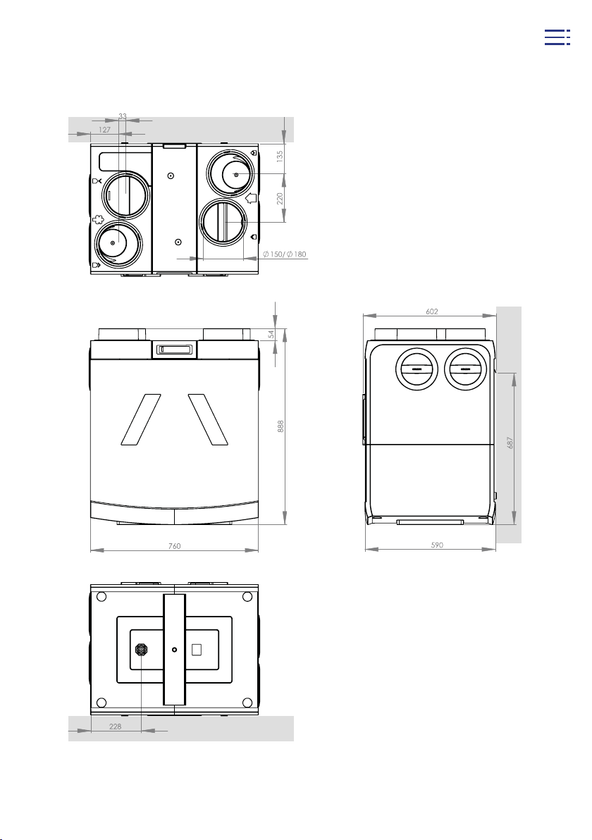
3.3 Dimensional drawing
index
8
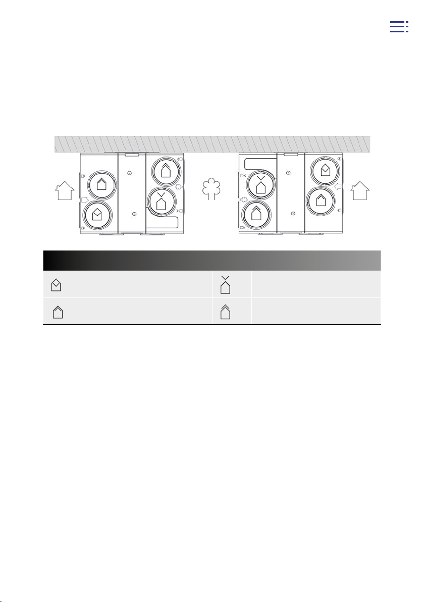
3.4 Duct indicator
When connecting the ducts it is important to take into consideration which
model is being used - left or right mounting. The connections are indicated on the top
of the unit with icons. The unit is supplied as a left model as standard.
You can change your apparatus into a right mounted model (see Section 4.3).
index
Left model
Home HomeOutside
Right model
Air ducts on the home side Air ducts on the outside
Supply air from the unit to
the home
Return air from the home to
the unit
Supply air from outside to
the unit
Extractor air from the unit to
the outside
9

4. Installation
4.1 Brief installation instructions
Step-by-step assembly:
1. Mount the wall bracket level on a wall with sufficient mass (200 kg/m2) with the
supplied bolts and plugs, or mount the unit on the optional base in the case of
floor mounting
2. Mount the Orcon extractor and supply valves in the various rooms
3. Configure the unit in the desired direction (see Chapter 4.3)
4. If desired, replace the earthed power cord with a perilex power cord
5. Set the required flow rate with the help of the DIP switches on the main circuit
board (see Chapter 6)
6. Hang the unit on the wall bracket, or position the unit with the base in the
desired location
7. Adjust the levelling feet so that the unit is hanging (wall mounting) or standing
(floor mounting) level
8. Install 2 silencers of at least 1 metre (ducts to and from interior spaces)
9. Mount the ventilation ducts and conduits with as little air resistance as possible
and free from leaks. Make sure no residual material from the pipes is able to reach
the device.
10. Mount the condensation extractor (preferably dry siphon) under the unit
11. Mount the desired remote controls, CV-3 switch (for perilex) and/or CO
(see Chapter 5)
12. Switch on the voltage of the HRC-EcoMax or HRC-MaxComfort unit
13. Report separately supplied remote controls and/or CO
sensors on
2
(see Chapter 5), the supplied remote control is already registered to the unit as
standard
sensors
2
index
4.2 Installation instructions
The HRC must be installed in compliance with:
• Quality requirements for residential ventilation systems, ISSO 61 quality requirements
for balanced ventilation in homes, ISSO 62
• The capacity calculation in compliance with the Netherlands Building Decree
• Requirements for ventilation of buildings - determination methods for new buildings
NEN 1087:2018
• The safety provisions for low-voltage installations, NEN 1010
• The requirements for connection to indoor drainage - design and implementation
guidelines, NTR 3216:2012. Any additional requirements from the local energy
companies
• The installation instructions for the HRC-EcoMax and/or HRC-MaxComfort
10

4.3 Changing the unit direction
The HRC is available in a left or right model. The HRC is by default supplied as a left
model. The ducts are therefore are connected to the home on the left side of the unit,
and the ducts on the right side of the unit go outside. If you wish to use the HRC as a
right model, it can be configured as follows:
1. Remove the plug from the socket
2. Place the device on a flat surface if the device is already suspended
3. Remove both filter covers
4. Remove the plastic front plate
5. Remove the metal front plate of the device by removing the 5 screws
(wrench size T25)
6. Take the power cord out of the cable clamp on the metal back plate
7. Remove the metal back plate of the device by removing the 5 screws.
8. Move the metal front plate to the other side of the device and fasten the 5 screws
9. Move the metal back plate to the back of the device and fasten the 5 screws
10. Remove the circuit board cover on the top. Keep an eye on the length of the display
cable when removing the circuit board cover. If necessary, temporarily separate it
from the connector on the circuit board
11. Move the earthing cable to the new back of the device. Move the strain relief
towards the recesses at the other wide of the circuit board as well
12. Reinstall the top cover such that the display is located at the front and fasten the 2
screws.
13. Return the earthing cable to the cable clamp on the metal back plate
14. Place the plastic front plate back to cover the metal front plate. Secure the front
plate by pressing on the four outer corners
15. Reinstall the filter covers.
index
The device is now suitable for installation in a right-handed setup.
11
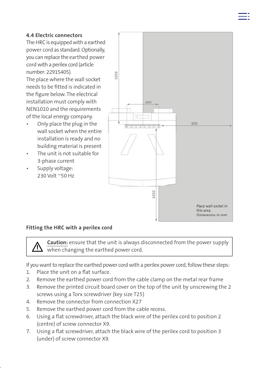
4.4 Electric connectors
The HRC is equipped with a earthed
power cord as standard. Optionally,
you can replace the earthed power
cord with a perilex cord (article
number: 22915405).
The place where the wall socket
needs to be fitted is indicated in
the figure below. The electrical
installation must comply with
NEN1010 and the requirements
of the local energy company.
• Only place the plug in the
wall socket when the entire
installation is ready and no
building material is present
• The unit is not suitable for
3-phase current
• Supply voltage:
230 Volt ~50 Hz
Fitting the HRC with a perilex cord
Caution: ensure that the unit is always disconnected from the power supply
when changing the earthed power cord.
If you want to replace the earthed power cord with a perilex power cord, follow these steps:
1. Place the unit on a flat surface.
2. Remove the earthed power cord from the cable clamp on the metal rear frame
3. Remove the printed circuit board cover on the top of the unit by unscrewing the 2
screws using a Torx screwdriver (key size T25)
4. Remove the connector from connection X27
5. Remove the earthed power cord from the cable recess.
6. Using a flat screwdriver, attach the black wire of the perilex cord to position 2
(centre) of screw connector X9.
7. Using a flat screwdriver, attach the black wire of the perilex cord to position 3
(under) of screw connector X9.
index
Location of socket
outlet relative to
wall bracket
12

8. Place the white connector of the perilex cord on connection X27.
9. Feed the perilex cord through the cable recess. Place the strain relief in the
appropriate recess.
10. Screw the strain relief hand tight using a Torx screwdriver (key size T20)
11. Replace the top cover and re-tighten the 2 screws
12. Reinsert the earthed perilex cord into the cable clamp on the metal back frame
13. Place the plug in a perilex wall socket which is connected as shown in the
diagram below.
Speed control for perilex connection
A 230 Volt power supply (terminals L3 and N) must be
connected to the perilex wall socket. The speed is controlled by means of a 3-position switch, which receives
power (L3) from the perilex socket (wire diameter 1.5
2
mm)
). A black (L2) and grey (L1) wire leads from the
switch back to the perilex wall socket. It is important
that terminal L3 is always supplied with voltage. For
the correct way to connect the cabling, see the wiring
diagram below. Optionally, an RF Remote Control, CO
Controlsensor or a CO
Roomsensor can be combined
2
2
with the CV-3 switch. If several switches or controls are
used in the home, the last selected ventilation position
always takes precedence.
index
Explanation of 3 ventilation settings
Setting 1
Setting 2
Position 3
Low Absent setting
Medium Present setting
High High setting
For use during absence during a long
period
For daily use with normal use within
the home
For use during cooking, showering
or parties
13
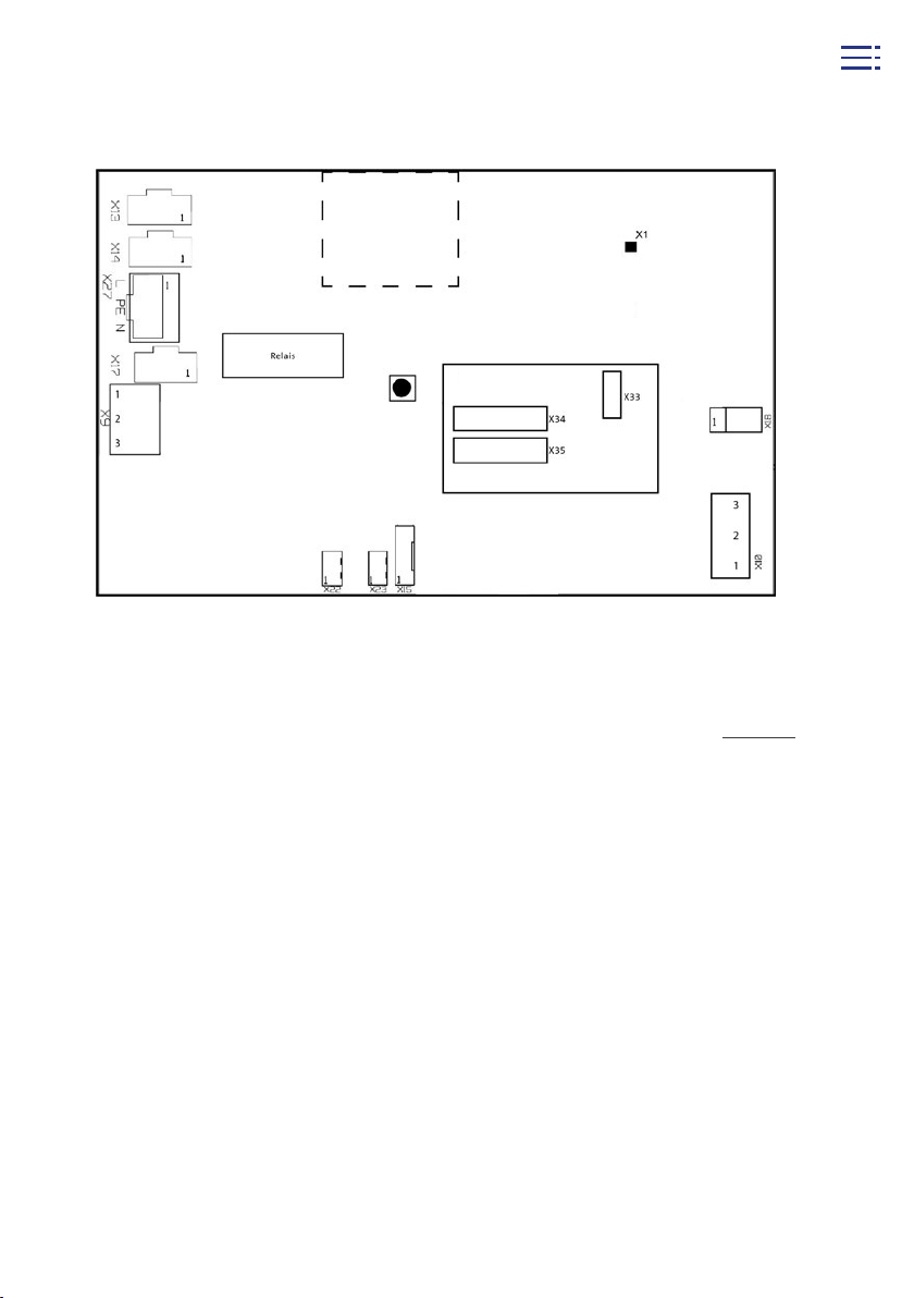
Connections to printed circuit board
No. Function Pin function
X1 RF antenna connection
L – 230V
X9 Perilex input
2 – L2 (black, 230V) Medium setting
3 – L1 (grey, 230V) High setting
1- RSA (2x White)
2- RSB (2x Brown)
3- GND (2x green)
X10
Modbus Communication duct to
ventilators
X13 Supply ventilator power supply 1 – L2 – PE3 – N
X14 Extractor ventilator power supply 1 – L2 – PE3 – N
X15 Bypass stepper motor control
X18 Humidity sensor input
index
X22
X23
Temperature sensor 1 input
(return air from inside)
Temperature sensor 2 input
(supply air from outside)
1 – Earth
2 – Sensor
1 – Earth
2 – Sensor
X27 230V mains 1 – L(3)2 – PE3 – N
X33* Display connection Flat cable
X34* DIP switches extractor 8 dip switches
X35* DIP switches supply 8 dip switches
*on top board
14
4.5 Installing the unit
Transformer
Add-on PCB
Menu
button
Wall mounting
The unit can be hung on the supplied wall bracket. But only if the wall has a minimum
mass of 200 kg/m
2
is available.
1. Attach the wall bracket to the wall using the bolts and plugs supplied. Caution:
mount the wall bracket using a spirit level before you connect the ducts!
Sufficient space must be left underneath the wall bracket for the condensation
extractor (see chapter 4.7).
2. Place the HRC in the left or right configuration over the wall bracket, by hooking
the hook on the back of the unit over the wall bracket.
3. Turn the levelling feet on the back of the unit so that it hangs level against the
wall. This ensures that the condensation extractor works optimally.
index
15
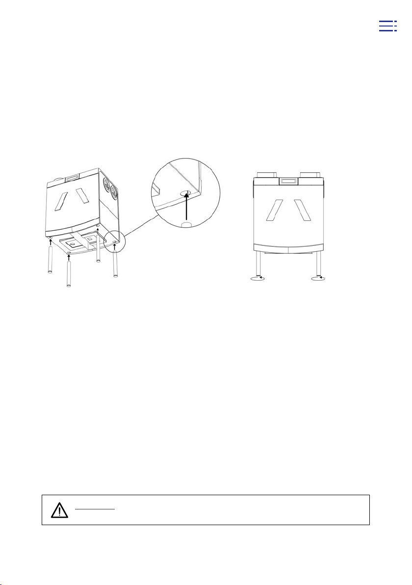
Floor mounting
If there is no wall that is suitable for wall mounting, the HRC can also be placed on
a concrete floor using the optional Orcon base (article number: 22700080) for floor
mounting.
1. Place the legs in the recesses on the bottom of the unit (Figure A). This works best
when the unit is on its side.
2. If necessary, use a spirit level to adjust the levelling feet so that the unit is level on
the floor (Figure B).
A. B.
4.6 Connecting ducts to the unit
Once the unit is fitted, the ducts can be mounted. The ducts (return) from and to
the home (supply) are on one side of the unit, and the ducts from and to the outside
are on the other side. In order to prevent condensation on the ducts from and to the
outside, these must always be insulated externally to ensure that they are dampproof. It is preferable to use preinsulated plastic ducts made of PE or PUR. Try to keep
these ducts as short as possible.
It is advisable to connect the ducts to and from the home to the unit using sound
dampers with a minimum length of 100 cm. When measuring the ducts, bear in mind
that not too much energy is lost when transporting the air through ducts that are
too narrow. It is preferable not to have the total resistance of both the supply system
and the discharge system exceed 100 Pascals. The supply duct system must be fitted
in such a way that NEN 1070, table 4 is complied with in the nominal setting. Think
of crosstalk and installation noise, also with underfloor ducts. Ensure that the supply
ducts are insulated if necessary, e.g. if they are installed outside the insulated skin.
index
16
Attention: make sure no residual material is able to reach the device while
installing the pipes to prevent it from damaging the device.
 Loading...