

Orcon HRC 300 4B P, HRC 300 4B RH, HRC 400 4B P, HRC 400 4B RH Maintenance Manual

Fitting and maintenance
instructions
Heat recovery unit
Type: HRC 300/400 4B(P/RH)
This manual is intended for
users and installers of type
HRC 300/400 B(P/RH).
This manual contains important about the operation
and installation of the
HRC 300/400 B(P/RH).
Store near the appliance
www.orcon.nl

Contents 1. General
1. General 2
2. Version 3
2.1 General 3
2.2 Fitting HRC in brief 3
3. Installation 4
3.1 Mounting frame 4
3.2 Important Instruction 4
3.3 Connecting ducts 4
3.4 Connecting condensate discharge 5
3.5 Placing the heat recovery module 6
3.6 Replacing the cover 6
3.7 Electrical connections 6
3.7.1 HRC with 4 core and earth cable 6
3.7.2 HRC with wireless remote control 6
3.7.3 Speed control with 4 core and earth cable
(BP model only) 6
3.7.4 Speed control with a wireless remote control
(BRH model only) 6
3.8 Overview connection HRC 7
3.9 Adjusting the air performance 7
4. Maintenance 10
4.1 User maintenance 10
4.2 Installer maintenance 11
4.3 Mounting of the heat-exchanger and the motor plates 12
4.4 LED indication / Fault warnings 12
5. Technical specifications 13
5.1 Wiring diagram Orcon HRC 300/400 4B(P/RH) 13
5.2 Appliance data HRC 300 4B(P/RH) 14
5.3 Fan graph HRC 300 4B(P/RH) 15
5.4 Appliance data HRC 400 4B(P/RH) 16
5.5 Fan graph HRC 400 4B(P/RH) 17
5.6 Setting transmitter / receiver (RH model only) 18
6. Maintenance 19
6.1 Exploded view HRC 19
To maintain a healthy indoor environment closely-controlled
ventilation is essential. There are many pollutants that will
affect the indoor air quality: human body waste products
in shape of CO2, dead skin, perspiration and moisture.
Add to this the waste product of cooking (cooking-smells),
showering (moisture), gases from building-materials and
the waste products of pets.
Without proper ventilation this environment would be perfect
for the growth of mould and subsequently damage to the
decoration and fabric of a dwelling.
The HRC unit is fitted with two fans: The exhaust fan ensures
that warm damp and polluted air as near as possible to
the source will be extracted. The exhausted air must be
replaced with fresh air and so the HRC heat recovery unit
has not only an exhaust fan but is also fitted with a supply
fan and air filters.
The supply air, which in winter is colder than the inside air, is
heated in the heat recovery unit using the heat of the exhaust
air by means of the heat-exchanger. This heat exchanger
has an efficiency of 97%, so a minimum loss of heat takes
place and the supply air temperature is at an acceptable
and comfortable level.
In the summer, when heat-recovery is not desirable, the air
does not go through the heat exchanger, but is diverted by
way of a bypass-valve. By doing this during the night, with
relatively cool supply air to ventilate the dwelling, a cooler
dwelling temperature is possible. This is automatically
detected and controlled by the unit electronics.
The electronics also ensures, that in winter, when ice-formation
in the exchanger is possible, the exchanger is defrosted, at a
time that is most comfortable to occupants of the dwelling.
Further the fan speed will automatically switch up to a
higher setting when a 5% increase in relative humidity is
detected within a 2 minute period (usually during showering
or cooking). After a preset period the unit will return to the
lower set speed. The fans are energy-low by the use of ECmotors with a constant (adjustable) air volume.
Declaration of conformity 19
2
Fitting and maintenance instructions HRC 300/400 4B(P/RH)
The filters in the unit ensure that the fresh supply air is clean
as it enters the dwelling. Also the extract air from the property
is filtered, so that the pollution of the heat exchanger is
minimised.
These filters have to be cleaned every month, depending
on the pollution. The electronics in the unit is fitted with a
timer for filter cleaning which automatically indicates when
it is time to clean the filters. The maximum period between
replacements of the filters will be a year.
2. Version
2.1 General
The Orcon HRC is a complete heat recovery unit, which is
fitted with an intelligent electronic control system to ensure
optimum efficiency and protection under all conditions.
The unit can easily be set up for left- or a right-handed operation. By changing the position of a module at the top of the
unit it can quickly be configured to accomodate the ducting
to outside on either the left or on the right side of the unit.
With the screws and plugs supplied fit the unit horizontally
to the wall. A standard the unit is delivered complete with a wall
mounting frame, fitting instructions, fixing kit and a condensate
discharge trap. A wireless remote control is an optional extra.
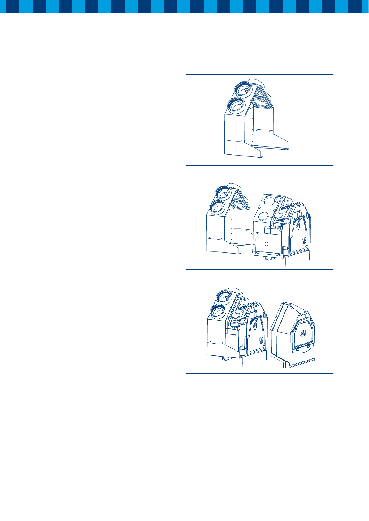
2.2 Fitting HRC in brief
A Mounting frame: Mounted by means of the screws and plugs
supplied horizontally to the wall. Use the fixing points on
the drawing attached to the mounting frame. When the frame
is mounted horizontally to the wall, the ducting runs can be
completed. Remember that both ducts to and from outside,
will be fitted to one side of the unit and the ducts to and from
the house are attached to the other side of the unit. Also
the condensate discharge under the unit can be fitted at
this stage.
A
B When the ducting runs are completed if an appropriate
electrical supply is present, the installation can be completed. Now the heat recovery module can be attached to
the frame. Ensure that the “tree” on the left/right module
corresponds to the side of the unit with the ducts to and
from outside and the “house” is on the internal side. On
the central PCB (3.1) adjust the air volume of the fans for
low, middle and high speed. Both fans are adjusted to the
same airflow to guarantee a balanced airflow. Push the heat
recovery module fully to the back of the mounting frame
and turn the handles at the bottom 180° to lock the unit
in place. Also the condensation trap under the unit can be
securely fastened with the wire clip supplied.
C The cover of the unit can now be replaced and secured with
the two screws and the power-supply can be connected. The
unit will start-up immediately and begin to run but must be
calibrated as described on page 13 in the start-up-procedure.
When there are no failures during the start-up, the unit is
ready and fully commissioned.
For further information about the operation, adjustment, failures
and maintenance of the unit, read the next pages carefully.
B
C
Fitting and maintenance instructions HRC 300/400 4B(P/RH)
3
3. Installation
switched spur) is also indicated. The unit must be secured
horizontally. Ensure sufficient angle for the condensate
discharge. The installation must be in a frost-free room.
Make sure there is a free space of at least 80 cm at the front of the
appliance for cleaning the filter and carrying out maintenance
on the appliance.
3.2 Important instruction
The HRC unit must be installed in accordance with all relevant
Building Regulations and Health & Safety requirements and the
fitting instructions of the HRC 300/400 4B(P/RH)
Connect mains after mounting the ducts!
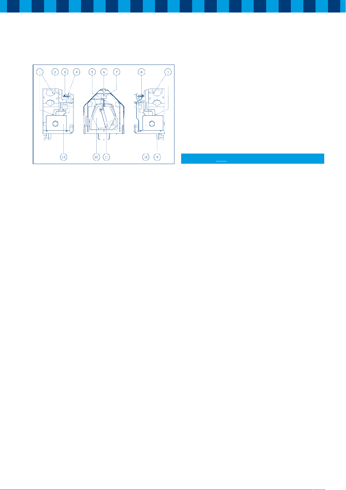
Figure 1: Parts of heat recovery module HRC 300/400 4B(P/RH)
1. Temperature sensor (4x)
Measures the temperatures in all connected ducts
2. Humidity sensor
Measures the relative humidity in the exhaust air
3. Central PCB ( 3.1)
This pcb controls the fans, sensors and decides which
function is activated
4. Dip switches
Used to adjust the airflow for each speed setting
5. Filters
Both supply and extract air is filtered
6. Left/Right module
For left or right-handed orientation (house-tree / tree-house)
7. Display Panel
Displays the current status and any failure of the HRC
8. Receiver PCB (only RH)
Pcb for wireless remote controlled HRC
9. Condensate-trap
Connection for condensate drain with water trap
10. Fan Right
Constant Flow fan with brushless EC motor supplies fresh
filtered air to the dwelling or extracts stale air from the
building depending on selected orientation of the HRC
11. Bypass valve
For supply of cool outside air in the summer
12. Heat exchanger
Takes care of the heat exchange between both airflows
13. Ventilator module left
Constant Flow fan with brushless EC motor supplies fresh
filtered air to or extracts stale air from the dwelling depending
on selected orientation of the HRC.
3.3 Connecting ducts
When the mounting frame is fitted, the ducts can be fitted.
On one side of the unit the duct to and from the dwelling, on
the other side the ducts from and to outside.
To prevent condensation on the outside of the exterior air,
the inlet duct and the air outlet duct from the HRC must be
insulated.
It is recommended that the ducts from and to the dwelling
and to the appliance use flexible ducting with a minimum
length of 150 cm and flexible connections of the ducts to and
from the outside to the appliance use flexible ducting with
a minimum length of 50 cm. Flexible ducting should be fully
extended but should not place any strain on the terminal or
fixings.
Remember when sizing the ducts that this part of the installation
will affect energy efficiency. So remember that energy will be
wasted, during the passage of the air through the ductwork,
if the ducts are too small. If possible ensure that the total
resistance of the inlet- as well as the exhaustsystem does not
exceed 100 Pascal.
3.1 Mounting frame
The mounting frame of the HRC can be fitted directly to the wall
with the delivered screws and plugs. The distance between both
mounting-holes will be 53 cm. Under the mounting frame
ensure there is at least 50 cm for the condensate discharge
to be connected. On the mounting frame is a drawing, which
indicates where to fit the condensate discharge. The position
of the electrical power supply (an earthed wall socket or fused
4
Fitting and maintenance instructions HRC 300/400 4B(P/RH)
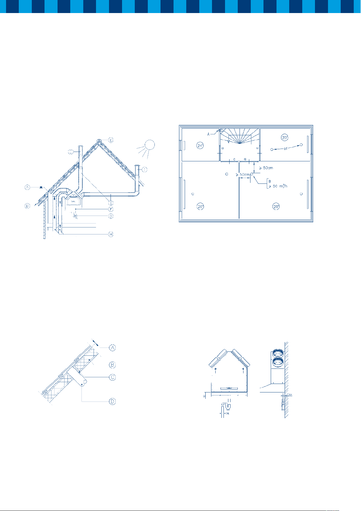
A = No exhaust too close to an air inlet
B = Ventilation inlet possible near roof end
C = Inlet roof terminal
D = Ventilated ridge tile
E = Duct from and to outside - insulated
F = HRC (horizontal position)
G = Condensate discharge conforms to installation instructions
H = Ducts from and to the dwelling acoustically insulated
I = Ventilation exhaust roof terminal
Figure 2: Connection example HRC
Arrange the exterior air supply from the sheltered side of the
dwelling, for instance from the wall. Install the exterior air
supply duct in such a manner that surface condensation is
prevented.
The mechanical ventilation outlet, the air inlet and any soil &
vent pipes should each be separated by at least one meter.
A = Outlet valve ø125 plastic (MKL) or metal (EFF-125)
B = Inlet valve ø100 (TFF-100) or ø125 (TFF-125)
a = Gap under the door 2 cm.
Figure 4: Location outlet and inlet valves
Install sufficient overflow openings, door gap 2 cm.
3.4 Connecting condensate discharge
The condensation-trap must be mounted at the bottom of the
HRC with the wire clip supplied.
Caution! Before mounting you have to fill the trap with water.
A = 10mm above roofing
B = roof insulation
C = insulated with PUR
D = duct for air inlet - insulate carefully
Figure 3: Discharge duct through the roof.
Feed the discharge duct through the roof void in such a manner
as to prevent condensation; in addition, the discharge duct
between the HRC and the roof terminal must be designed to
prevent surface condensation.
The diameter of pipework to the air-trap is 32 or 40 mm. The
position of the drain is indicated at the drawing in the mounting
frame. The condensate water must leave through the drain
pipe. Take care that the distance between siphon and air-trap
will be enough for de-mounting and cleaning.
Figure 5: Connection of HRC to drain pipe
Fitting and maintenance instructions HRC 300/400 4B(P/RH)
5

3.5 Placing the heat recovery module
After fitting all the ducts at the mounting frame, and after fitting
the condensate discharge, the “heart” of the unit can now be
installed. Take the heat recovery module from the carton and
push it from the front into the mounting frame.
Push the unit fully to the back and secure by turning the handles
at the bottom 180°.
Figure 6: Placing the heat recovery module of the HRC
3.7.4 Speed control with a wireless remote control
(BRH model only)
The HRC 300/400 BRH is delivered prewired. The unit must be
connected to 230V~50Hz supply by means of a 3A fused spur.
3 = High
2 = Middle
1 = Low
Auto = No function
Figure 7: Wireless remote control
See § 5.4.2 for settings of the wireless remote controller.
After positioning the heat recovery module, the dip switches
can be adjusted to give the desired air volume. (See § 3.9)
Ensure that the filters are correctly located.
3.6 Replacing the cover
After the heat recovery module is fixed in place the cover
can be attached. Offer up the cover with its front pointing
downwards. Hook the two brackets on the lower part of the
cover into the slots in the mounting frame. Now you can fix
the upper side of the cover at the upper side of the mounting
frame with the two screws provided. If it is difficult to push
the cover totally against the unit open the flap in the cover.
After closing the cover (and flap) the unit can be connected
to the power supply.
3.7 Electrical connections
3.7.1 HRC with 4 core and earth cable
The electric installation must comply with the local regulations.
3.7.2 HRC with wireless remote control
The electric installation must comply with the local regulations.
3.7.3 Speed control with 4 core and earth cable (BP model only)
The unit requires a power supply of 230 Volt (terminal L3 and N).
The speed control takes place by means of a 3-speed switch and
utilising 4 core and earth cabling to the unit.
For the correct wiring diagram see § 5.1.
6
Fitting and maintenance instructions HRC 300/400 4B(P/RH)
 Loading...