

Page 1

Orcad® Capture
User’s Guide
Page 2

Copyright © 1985-2000 Cadence Design Systems, Inc. All rights reserved.
Trademarks
Allegro, Ambit, BuildGates, Cadence, Cadence logo, Concept, Diva, Dracula, Gate
Ensemble, NC Verilog, OpenBook online documentation library, Orcad, Orcad
Capture, PSpice, SourceLink online customer support, SPECCTRA, Spectre, Vampire,
Verifault-XL, Verilog, Verilog-XL, and Virtuoso are registered trademarks of Cadence
Design Systems, Inc.
Affirma, Assura, Cierto, Envisia, Mercury Plus, Quickturn, Radium, Silicon Ensemble,
and SPECCTRAQuest are trademarks of Cadence Design Systems, Inc.
Alanza is a service mark of Cadence Design Systems, Inc.
All other brand and product names mentioned herein are used for identification
purposes only and are registered trademarks, trademarks, or service marks of their
respective holders.
60-30-611
Second edition 31 May 2000
Cadence PCB Systems Division (PSD) offices
PSD main office (Portland) (503) 671-9500
PSD Irvine office (949) 788-6080
PSD Japan office 81-45-682-5770
PSD UK office 44-1256-381-400
PSD customer support (877) 237-4911
PSD web site www.orcad.com
PSD customer support web page www.orcad.com/technical/technical.asp
PSD customer support email form www.orcad.com/technical/email_support.asp
Cadence PCB Systems Division
13221 SW 68th Parkway, Su ite 200
Portland, OR 97223
Page 3

Contents
Contents iii
Before you begin xvii
Welcome . . . . . . . . . . . . . . . . . . . . . . . . . . . . . . . . . . . . xvii
How to use this guide . . . . . . . . . . . . . . . . . . . . . . . . . . . . xviii
Symbols and conventions . . . . . . . . . . . . . . . . . . . . . . . xviii
Related documentation . . . . . . . . . . . . . . . . . . . . . . . . . . xix
Part One Capture basics
Getting started 3Chapter 1
Starting Capture . . . . . . . . . . . . . . . . . . . . . . . . . . . . . . . . . 3
The Capture session frame . . . . . . . . . . . . . . . . . . . . . . . . . . . 4
The Capture work environment 5Chapter 2
The project manager . . . . . . . . . . . . . . . . . . . . . . . . . . . . . . . 6
Project manager folders . . . . . . . . . . . . . . . . . . . . . . . . . . . 6
Project manager tabs—File and Hierarchy . . . . . . . . . . . . . . . . 9
Single view . . . . . . . . . . . . . . . . . . . . . . . . . . . . . . . . . . 9
Flat and hierarchical designs . . . . . . . . . . . . . . . . . . . . . . . . 10
Project manager pop-up menus . . . . . . . . . . . . . . . . . . . . . . 10
The schematic page editor . . . . . . . . . . . . . . . . . . . . . . . . . . . 11
The part editor . . . . . . . . . . . . . . . . . . . . . . . . . . . . . . . . . . 12
The programmer’s editor . . . . . . . . . . . . . . . . . . . . . . . . . . . . 13
The session log . . . . . . . . . . . . . . . . . . . . . . . . . . . . . . . . . . 14
The toolbar . . . . . . . . . . . . . . . . . . . . . . . . . . . . . . . . . . . . 16
Displaying or hiding the toolbar . . . . . . . . . . . . . . . . . . . . . . 18
The tool palettes . . . . . . . . . . . . . . . . . . . . . . . . . . . . . . . . . 19
The schematic page editor tool palette . . . . . . . . . . . . . . . . . . 19
The part editor tool palette . . . . . . . . . . . . . . . . . . . . . . . . . 22
Page 4

Contents
Displaying or hiding a tool palette . . . . . . . . . . . . . . . . . . . . 24
The status bar . . . . . . . . . . . . . . . . . . . . . . . . . . . . . . . . . . 25
Left field . . . . . . . . . . . . . . . . . . . . . . . . . . . . . . . . . . . 25
Center field . . . . . . . . . . . . . . . . . . . . . . . . . . . . . . . . . 25
Right field . . . . . . . . . . . . . . . . . . . . . . . . . . . . . . . . . . 25
Displaying or hiding the status bar . . . . . . . . . . . . . . . . . . . 26
Selecting and deselecting objects . . . . . . . . . . . . . . . . . . . . . . . 27
Grouping objects . . . . . . . . . . . . . . . . . . . . . . . . . . . . . . 29
Editing properties . . . . . . . . . . . . . . . . . . . . . . . . . . . . . . . 30
Instance and occurrence properties . . . . . . . . . . . . . . . . . . . 31
Instance properties . . . . . . . . . . . . . . . . . . . . . . . . . . 31
Occurrence properties . . . . . . . . . . . . . . . . . . . . . . . . . 31
The Browse spreadsheet editor . . . . . . . . . . . . . . . . . . . . . . 32
The property editor . . . . . . . . . . . . . . . . . . . . . . . . . . . . 35
The property editor window . . . . . . . . . . . . . . . . . . . . . 36
The property editor Filter menu . . . . . . . . . . . . . . . . . . . 40
Using the property editor . . . . . . . . . . . . . . . . . . . . . . . 43
The Package Properties spreadsheet editor . . . . . . . . . . . . . . . 46
Moving and resizing graphic objects . . . . . . . . . . . . . . . . . . . . . 48
Undoing, redoing, and repeating an action . . . . . . . . . . . . . . . . . 49
Using the Accessories menu . . . . . . . . . . . . . . . . . . . . . . . . . 51
iv
Starting a project 51Chapter 3
Creating new projects, designs, libraries, and VHDL files . . . . . . . . . 52
Opening existing projects, designs, libraries, and VHDL files . . . . . . 55
Working with files in a project . . . . . . . . . . . . . . . . . . . . . . . . 57
Saving projects, designs, and libraries . . . . . . . . . . . . . . . . . . . . 58
Closing a project . . . . . . . . . . . . . . . . . . . . . . . . . . . . . . . . 59
Archiving a project . . . . . . . . . . . . . . . . . . . . . . . . . . . . . . 61
Setting up your project 63Chapter 4
Defining your preferences . . . . . . . . . . . . . . . . . . . . . . . . . . . 65
Defining colors/print options . . . . . . . . . . . . . . . . . . . . . . 66
Controlling the grid . . . . . . . . . . . . . . . . . . . . . . . . . . . . 68
Setting pan and zoom . . . . . . . . . . . . . . . . . . . . . . . . . . . 69
Defining selection options . . . . . . . . . . . . . . . . . . . . . . . . 71
Setting miscellaneous options . . . . . . . . . . . . . . . . . . . . . . 73
Setting text editor options . . . . . . . . . . . . . . . . . . . . . . . . . 76
Setting up your project template . . . . . . . . . . . . . . . . . . . . . . . 78
Setting up fonts for new projects . . . . . . . . . . . . . . . . . . . . . 79
Defining title block information . . . . . . . . . . . . . . . . . . . . . 80
Page 5

Contents
Setting the schematic page size for new projects . . . . . . . . . . . . . 82
Defining the grid reference . . . . . . . . . . . . . . . . . . . . . . . . . 84
Defining the default hierarchy option for new projects . . . . . . . . . 86
Setting up compatibility with Orcad’s Schematic Design Tools (SDT) 87
Changing properties of existing projects . . . . . . . . . . . . . . . . . . . 88
Assigning fonts . . . . . . . . . . . . . . . . . . . . . . . . . . . . . . . 89
Defining hierarchy . . . . . . . . . . . . . . . . . . . . . . . . . . . . . 89
Using Capture with SDT . . . . . . . . . . . . . . . . . . . . . . . . . . 89
Viewing design information . . . . . . . . . . . . . . . . . . . . . . . . 90
Viewing and connecting to invisible power pins . . . . . . . . . . . . 91
Changing properties of existing schematic pages . . . . . . . . . . . . . . 92
Changing page size . . . . . . . . . . . . . . . . . . . . . . . . . . . . . 92
Setting up new grid references . . . . . . . . . . . . . . . . . . . . . . . 93
Viewing miscellaneous schematic page properties . . . . . . . . . . . 93
Printing and plotting 95Chapter 5
Printing or plotting schematic pages . . . . . . . . . . . . . . . . . . . . . 96
Printing or plotting parts or packages . . . . . . . . . . . . . . . . . . . . . 97
Printing the session log and text editor windows . . . . . . . . . . . . . . 98
Previewing printer or plotter output . . . . . . . . . . . . . . . . . . . . . 99
Scaling printer or plotter output . . . . . . . . . . . . . . . . . . . . . . . 100
Special considerations for plotting . . . . . . . . . . . . . . . . . . . . . . 101
Plotter pen colors . . . . . . . . . . . . . . . . . . . . . . . . . . . . . 101
Part Two Creating designs
Design structure 105Chapter 6
Flat designs . . . . . . . . . . . . . . . . . . . . . . . . . . . . . . . . . . . 106
Hierarchical designs . . . . . . . . . . . . . . . . . . . . . . . . . . . . . . 107
Simple hierarchical designs . . . . . . . . . . . . . . . . . . . . . . . 107
Complex hierarchies . . . . . . . . . . . . . . . . . . . . . . . . . . . 109
Connecting schematic folders and schematic pages . . . . . . . . . . . . 110
Hierarchical blocks . . . . . . . . . . . . . . . . . . . . . . . . . . . . 110
Hierarchical ports . . . . . . . . . . . . . . . . . . . . . . . . . . . . . 111
Hierarchical pins . . . . . . . . . . . . . . . . . . . . . . . . . . . . . 111
Off-page connectors . . . . . . . . . . . . . . . . . . . . . . . . . . . . 112
An example: creating a simple hierarchy . . . . . . . . . . . . . . . . . . 113
Placing, editing, and connecting parts and symbols 115Chapter 7
Placing and editing parts . . . . . . . . . . . . . . . . . . . . . . . . . . . 117
v
Page 6

Contents
Placing parts . . . . . . . . . . . . . . . . . . . . . . . . . . . . . . . . 118
Place Part dialog box . . . . . . . . . . . . . . . . . . . . . . . . . 121
Most Recently Used (MRU) part list . . . . . . . . . . . . . . . . . 124
Searching for parts . . . . . . . . . . . . . . . . . . . . . . . . . . . . . 125
Editing parts . . . . . . . . . . . . . . . . . . . . . . . . . . . . . . . . 125
Placing and editing power and ground symbols . . . . . . . . . . . . . . 128
Placing power and ground symbols . . . . . . . . . . . . . . . . . . . 128
Place Power and Place Ground dialog boxes . . . . . . . . . . . . 130
Editing power and ground symbols . . . . . . . . . . . . . . . . . . . 131
Placing and editing no-connect symbols . . . . . . . . . . . . . . . . . . . 132
Placing no-connect symbols . . . . . . . . . . . . . . . . . . . . . . . 132
Editing no-connect symbols . . . . . . . . . . . . . . . . . . . . . . . 133
Placing and editing hierarchical blocks . . . . . . . . . . . . . . . . . . . 134
Placing hierarchical blocks . . . . . . . . . . . . . . . . . . . . . . . . 134
Place Hierarchical Block dialog box . . . . . . . . . . . . . . . . . 136
Editing hierarchical blocks . . . . . . . . . . . . . . . . . . . . . . . . 138
Placing and editing hierarchical ports and hierarchical pins . . . . . . . 139
Placing hierarchical ports . . . . . . . . . . . . . . . . . . . . . . . . . 139
Place Hierarchical Port dialog box . . . . . . . . . . . . . . . . . 140
Placing hierarchical pins . . . . . . . . . . . . . . . . . . . . . . . . . 141
Place Hierarchical Pin dialog box . . . . . . . . . . . . . . . . . . 143
Editing hierarchical ports and hierarchical pins . . . . . . . . . . . . 143
Placing and editing off-page connectors . . . . . . . . . . . . . . . . . . . 144
Placing off-page connectors . . . . . . . . . . . . . . . . . . . . . . . . 144
Place Off-Page Connector dialog box . . . . . . . . . . . . . . . . 146
Editing off-page connectors . . . . . . . . . . . . . . . . . . . . . . . . 147
Placing and connecting wires and buses . . . . . . . . . . . . . . . . . . . 148
Placing wires . . . . . . . . . . . . . . . . . . . . . . . . . . . . . . . . 149
Editing wires . . . . . . . . . . . . . . . . . . . . . . . . . . . . . . . . 150
Moving wires . . . . . . . . . . . . . . . . . . . . . . . . . . . . . . . . 151
Placing buses . . . . . . . . . . . . . . . . . . . . . . . . . . . . . . . . 152
Editing buses . . . . . . . . . . . . . . . . . . . . . . . . . . . . . . . . 153
Placing bus entries . . . . . . . . . . . . . . . . . . . . . . . . . . . . . 153
Editing bus entries . . . . . . . . . . . . . . . . . . . . . . . . . . . . . 154
Ripping a subset of signals off the bus . . . . . . . . . . . . . . . . . . 155
vi
Adding and editing graphics and text 157Chapter 8
Drawing tools . . . . . . . . . . . . . . . . . . . . . . . . . . . . . . . . . . 158
Drawing lines . . . . . . . . . . . . . . . . . . . . . . . . . . . . . . . . . . 159
Drawing rectangles and squares . . . . . . . . . . . . . . . . . . . . . . . 160
Drawing circles and ellipses . . . . . . . . . . . . . . . . . . . . . . . . . 161
Page 7

Contents
Drawing arcs . . . . . . . . . . . . . . . . . . . . . . . . . . . . . . . . . . 162
Drawing polylines and polygons . . . . . . . . . . . . . . . . . . . . . . 163
Adding fill to an object . . . . . . . . . . . . . . . . . . . . . . . . . . . . 164
Mirroring an object . . . . . . . . . . . . . . . . . . . . . . . . . . . . . . 164
Rotating an object . . . . . . . . . . . . . . . . . . . . . . . . . . . . . . . 165
Moving an object . . . . . . . . . . . . . . . . . . . . . . . . . . . . . . . . 165
Cutting an object . . . . . . . . . . . . . . . . . . . . . . . . . . . . . . . . 165
Copying an object . . . . . . . . . . . . . . . . . . . . . . . . . . . . . . . 166
Pasting an object . . . . . . . . . . . . . . . . . . . . . . . . . . . . . . . . 166
Deleting a selected object . . . . . . . . . . . . . . . . . . . . . . . . . . . 166
Placing a bitmap . . . . . . . . . . . . . . . . . . . . . . . . . . . . . . . . 167
Placing text . . . . . . . . . . . . . . . . . . . . . . . . . . . . . . . . . . . 168
The text bounding box . . . . . . . . . . . . . . . . . . . . . . . . . . 170
Deleting text . . . . . . . . . . . . . . . . . . . . . . . . . . . . . . . . 170
Modifying text . . . . . . . . . . . . . . . . . . . . . . . . . . . . . . . 170
Finding text . . . . . . . . . . . . . . . . . . . . . . . . . . . . . . . . 171
Replacing text . . . . . . . . . . . . . . . . . . . . . . . . . . . . . . . 172
Importing text . . . . . . . . . . . . . . . . . . . . . . . . . . . . . . . 172
Exporting text . . . . . . . . . . . . . . . . . . . . . . . . . . . . . . . 173
Character formatting . . . . . . . . . . . . . . . . . . . . . . . . . . . 173
About screen fonts . . . . . . . . . . . . . . . . . . . . . . . . . . . . . 174
Using macros 175Chapter 9
Recording a macro . . . . . . . . . . . . . . . . . . . . . . . . . . . . . . . 177
Playing a macro . . . . . . . . . . . . . . . . . . . . . . . . . . . . . . . . 178
Configuring a macro . . . . . . . . . . . . . . . . . . . . . . . . . . . . . . 179
Configure Macro dialog box . . . . . . . . . . . . . . . . . . . . . 180
Naming a macro . . . . . . . . . . . . . . . . . . . . . . . . . . . . . . . . 183
Assigning a shortcut key to a macro . . . . . . . . . . . . . . . . . . . . . 185
Sample macros . . . . . . . . . . . . . . . . . . . . . . . . . . . . . . . . . 186
Changing your view of a schematic page 187Chapter 10
Zooming . . . . . . . . . . . . . . . . . . . . . . . . . . . . . . . . . . . . 188
Zooming to a specified scale . . . . . . . . . . . . . . . . . . . . . . . 189
Other viewing options . . . . . . . . . . . . . . . . . . . . . . . . . . 189
Moving to a new location . . . . . . . . . . . . . . . . . . . . . . . . . . . 192
Moving to an X, Y location . . . . . . . . . . . . . . . . . . . . . . . . 192
Go To dialog box, Location tab . . . . . . . . . . . . . . . . . . . 193
Jumping to a specific grid reference . . . . . . . . . . . . . . . . . . . 194
Go To dialog box, Grid Reference tab . . . . . . . . . . . . . . . . 194
Jumping to a marked location . . . . . . . . . . . . . . . . . . . . . . 195
vii
Page 8

Contents
Go To dialog box, Bookmark tab . . . . . . . . . . . . . . . . . . . 196
Displaying the grid and grid references . . . . . . . . . . . . . . . . . . . 197
Finding parts in a project . . . . . . . . . . . . . . . . . . . . . . . . . . . 198
Part Three Libraries and parts
About libraries and parts 201Chapter 11
Libraries . . . . . . . . . . . . . . . . . . . . . . . . . . . . . . . . . . . . . 202
Parts . . . . . . . . . . . . . . . . . . . . . . . . . . . . . . . . . . . . . . . 203
About part instances and part occurrences . . . . . . . . . . . . . . . 204
The design cache . . . . . . . . . . . . . . . . . . . . . . . . . . . . . . . . 205
Primitive and nonprimitive parts . . . . . . . . . . . . . . . . . . . . . . . 208
Creating and editing parts 209Chapter 12
Parts and packages: homogeneous or heterogeneous . . . . . . . . . . . 210
Creating a new part . . . . . . . . . . . . . . . . . . . . . . . . . . . . . . 211
Defining a part . . . . . . . . . . . . . . . . . . . . . . . . . . . . . . . 211
New Part Properties dialog box . . . . . . . . . . . . . . . . . . . 214
Attaching a schematic folder to a part . . . . . . . . . . . . . . . . . . 216
Adding graphics, text, and IEEE symbols to a part . . . . . . . . . . 217
Placing pins on a part . . . . . . . . . . . . . . . . . . . . . . . . . . . 218
Place Pin dialog box . . . . . . . . . . . . . . . . . . . . . . . . . . 220
Place Pin Array dialog box . . . . . . . . . . . . . . . . . . . . . . 225
About power and ground pins . . . . . . . . . . . . . . . . . . . . . . . . 227
Displaying invisible power pins . . . . . . . . . . . . . . . . . . . . . 228
Editing an existing part . . . . . . . . . . . . . . . . . . . . . . . . . . . . 229
Editing a part in a library . . . . . . . . . . . . . . . . . . . . . . . . . 229
Editing a part on a schematic page . . . . . . . . . . . . . . . . . . . . 230
Editing part properties . . . . . . . . . . . . . . . . . . . . . . . . . . 231
Default part properties . . . . . . . . . . . . . . . . . . . . . . . . 232
Viewing parts in a package . . . . . . . . . . . . . . . . . . . . . . . . . . 234
Editing parts in a package . . . . . . . . . . . . . . . . . . . . . . . . . . . 235
Editing part and package properties in the part editor . . . . . . . . . . 236
Viewing a part’s convert . . . . . . . . . . . . . . . . . . . . . . . . . . . . 239
Part Four Processing your design
About the processing tools 243Chapter 13
Tools overview . . . . . . . . . . . . . . . . . . . . . . . . . . . . . . . . . 244
viii
Page 9

Contents
Updating instances and occurrences . . . . . . . . . . . . . . . . . . 246
Preparing to create a netlist 247Chapter 14
Annotating . . . . . . . . . . . . . . . . . . . . . . . . . . . . . . . . . . . 247
Annotate dialog box . . . . . . . . . . . . . . . . . . . . . . . . . 249
Updating properties . . . . . . . . . . . . . . . . . . . . . . . . . . . . . . 251
Update Properties dialog box . . . . . . . . . . . . . . . . . . . . 253
Update file format . . . . . . . . . . . . . . . . . . . . . . . . . . . 255
Checking for design rules violations . . . . . . . . . . . . . . . . . . . . 256
Design Rules Check dialog box, Design Rules Check tab . . . . 259
Design Rules Check dialog box, ERC Matrix tab . . . . . . . . . 262
Sample Design Rules Check report . . . . . . . . . . . . . . . . . 263
Back annotating . . . . . . . . . . . . . . . . . . . . . . . . . . . . . . . . 266
Back Annotate dialog box . . . . . . . . . . . . . . . . . . . . . . 268
Swap file format . . . . . . . . . . . . . . . . . . . . . . . . . . . . 269
Creating a netlist 271Chapter 15
Using the Create Netlist tool . . . . . . . . . . . . . . . . . . . . . . . . . 271
Netlist format files . . . . . . . . . . . . . . . . . . . . . . . . . . . . . . . 273
Netname resolution . . . . . . . . . . . . . . . . . . . . . . . . . . . . . . 274
Creating reports 275Chapter 16
Creating a bill of materials . . . . . . . . . . . . . . . . . . . . . . . . . . 275
Bill of Materials dialog box . . . . . . . . . . . . . . . . . . . . . . 277
Include file format . . . . . . . . . . . . . . . . . . . . . . . . . . . . . 279
Creating a cross reference report . . . . . . . . . . . . . . . . . . . . . . . 280
Cross Reference Parts dialog box . . . . . . . . . . . . . . . . . . 281
Exporting and importing schematic data 283Chapter 17
Exporting and importing designs . . . . . . . . . . . . . . . . . . . . . . 283
Exporting designs . . . . . . . . . . . . . . . . . . . . . . . . . . . . . 284
Importing designs . . . . . . . . . . . . . . . . . . . . . . . . . . . . . 285
Exporting and importing properties . . . . . . . . . . . . . . . . . . . . . 286
Exporting properties . . . . . . . . . . . . . . . . . . . . . . . . . . . 286
Property file format . . . . . . . . . . . . . . . . . . . . . . . . . . . . 288
Editing a property file . . . . . . . . . . . . . . . . . . . . . . . . . . . 288
Importing properties . . . . . . . . . . . . . . . . . . . . . . . . . . . 290
Generating a part 293Chapter 18
Using the Generate Part tool . . . . . . . . . . . . . . . . . . . . . . . . . 294
ix
Page 10

Contents
Generate a new part . . . . . . . . . . . . . . . . . . . . . . . . . . . . 294
Update the pin numbers of an existing part . . . . . . . . . . . . . . 297
Using Capture with Orcad Layout 299Chapter 19
Preparing your Capture design for use with Layout . . . . . . . . . . . . 301
Creating a netlist for use in Layout . . . . . . . . . . . . . . . . . . . . . . 303
Loading a new netlist into Layout . . . . . . . . . . . . . . . . . . . . . . 304
Back annotating board information from Layout . . . . . . . . . . . . . . 306
Forward annotating schematic data to Layout . . . . . . . . . . . . . . . 307
Cross probing between Capture and Layout . . . . . . . . . . . . . . . . 308
Enabling intertool communication between Capture and Layout . . 308
Cross probing from Capture to Layout . . . . . . . . . . . . . . . . . 309
Cross probing from Layout to Capture . . . . . . . . . . . . . . . . . 310
General rules . . . . . . . . . . . . . . . . . . . . . . . . . . . . . . . . . . 311
Using Capture with PSpice 313Chapter 20
Overview . . . . . . . . . . . . . . . . . . . . . . . . . . . . . . . . . . . . 313
Specifying simulation model libraries . . . . . . . . . . . . . . . . . . . . 314
Creating a design for PSpice A/D simulation . . . . . . . . . . . . . . . . 315
Editing simulation models from Capture . . . . . . . . . . . . . . . . . . 316
Adding and defining stimulus . . . . . . . . . . . . . . . . . . . . . . . . 317
Placing stimulus sources . . . . . . . . . . . . . . . . . . . . . . . . . 317
Using the Stimulus Editor . . . . . . . . . . . . . . . . . . . . . . . . . 317
Setting up and running analyses . . . . . . . . . . . . . . . . . . . . . . . 318
Viewing results . . . . . . . . . . . . . . . . . . . . . . . . . . . . . . . . . 319
Viewing results as you simulate . . . . . . . . . . . . . . . . . . . . . 319
Using markers . . . . . . . . . . . . . . . . . . . . . . . . . . . . . . . 319
Configuring the display of simulation results . . . . . . . . . . . . . 320
Creating designs for PSpice simulation and board layout . . . . . . . . . 321
Handling unmodeled pins . . . . . . . . . . . . . . . . . . . . . . . . 322
Displaying bias point information . . . . . . . . . . . . . . . . . . . . . . 323
Displaying bias point values . . . . . . . . . . . . . . . . . . . . . . . 323
Glossary 325
Index 337
x
Page 11

Figures
Figure 1 Capture’s session frame . . . . . . . . . . . . . . . . . . . . . . . . . . . . . 4
Figure 2 New project manager window . . . . . . . . . . . . . . . . . . . . . . . . . 6
Figure 3 File tab . . . . . . . . . . . . . . . . . . . . . . . . . . . . . . . . . . . . . . 9
Figure 4 Hierarchy tab . . . . . . . . . . . . . . . . . . . . . . . . . . . . . . . . . . . 9
Figure 5 Schematic page editor . . . . . . . . . . . . . . . . . . . . . . . . . . . . . . 11
Figure 6 Part editor . . . . . . . . . . . . . . . . . . . . . . . . . . . . . . . . . . . . 12
Figure 7 Programmer’s editor . . . . . . . . . . . . . . . . . . . . . . . . . . . . . . 13
Figure 8 Session log . . . . . . . . . . . . . . . . . . . . . . . . . . . . . . . . . . . . 14
Figure 9 Capture’s toolbar . . . . . . . . . . . . . . . . . . . . . . . . . . . . . . . . 16
Figure 10 Schematic page editor tool palette . . . . . . . . . . . . . . . . . . . . . . . 19
Figure 11 Part editor tool palette . . . . . . . . . . . . . . . . . . . . . . . . . . . . . . 22
Figure 12 The status bar . . . . . . . . . . . . . . . . . . . . . . . . . . . . . . . . . . 25
Figure 13 Browse spreadsheet editor . . . . . . . . . . . . . . . . . . . . . . . . . . . 32
Figure 14 Property editor . . . . . . . . . . . . . . . . . . . . . . . . . . . . . . . . . . 36
Figure 15 Package Properties spreadsheet editor . . . . . . . . . . . . . . . . . . . . 46
Figure 16 Open project, design, and schematic page . . . . . . . . . . . . . . . . . . 55
Figure 17 Open library . . . . . . . . . . . . . . . . . . . . . . . . . . . . . . . . . . . 56
Figure 18 Open VHDL file . . . . . . . . . . . . . . . . . . . . . . . . . . . . . . . . . 56
Figure 19 Colors/Print tab of the Preferences dialog box . . . . . . . . . . . . . . . . 66
Figure 20 Grid Display tab of the Preferences dialog box . . . . . . . . . . . . . . . . 68
Figure 21 Pan and Zoom tab of the Preferences dialog box . . . . . . . . . . . . . . . 69
Figure 22 Select tab of the Preferences dialog box . . . . . . . . . . . . . . . . . . . . 71
Figure 23 Miscellaneous tab of the Preferences dialog box . . . . . . . . . . . . . . . 73
Figure 24 Text Editor tab of the Preferences dialog box . . . . . . . . . . . . . . . . . 76
Figure 25 Fonts tab of the Design Template dialog box . . . . . . . . . . . . . . . . . 79
Figure 26 Title Block tab of the Design Template dialog box . . . . . . . . . . . . . . 80
Figure 27 Title block . . . . . . . . . . . . . . . . . . . . . . . . . . . . . . . . . . . . . 81
Figure 28 Page Size tab of the Design Template dialog box . . . . . . . . . . . . . . 82
Figure 29 Grid Reference tab of the Design Template dialog box . . . . . . . . . . . 84
Figure 30 Hierarchy tab of the Design Template dialog box . . . . . . . . . . . . . . 86
Figure 31 SDT Compatibility tab of the Design Template dialog box . . . . . . . . . 87
Figure 32 Miscellaneous tab of the Design Properties dialog box . . . . . . . . . . . 90
Page 12

Figures
Figure 33 Miscellaneous tab of the Schematic Page Properties dialog box . . . . . 93
Figure 34 An abstract representation of a simple hierarchy. . . . . . . . . . . . . . 107
Figure 35 A simple hierarchical design, as seen in the project manager . . . . . . . 108
Figure 36 An abstract representation of a complex hierarchy . . . . . . . . . . . . . 109
Figure 37 A complex hierarchical design, as seen in the project manager . . . . . . 109
Figure 38 Schematics before hierarchy . . . . . . . . . . . . . . . . . . . . . . . . . . 113
Figure 39 Schematics with hierarchy . . . . . . . . . . . . . . . . . . . . . . . . . . . 113
Figure 40 Schematics carrying a net . . . . . . . . . . . . . . . . . . . . . . . . . . . 114
Figure 41 Connectivity across pages in a schematic . . . . . . . . . . . . . . . . . . 114
Figure 42 Schematic with power and ground symbols . . . . . . . . . . . . . . . . 115
Figure 43 Part editor in package view . . . . . . . . . . . . . . . . . . . . . . . . . . 117
Figure 44 Part editor in part view . . . . . . . . . . . . . . . . . . . . . . . . . . . . 118
Figure 45 Place Part dialog box . . . . . . . . . . . . . . . . . . . . . . . . . . . . . . 121
Figure 46 Property editor with filter set to Capture . . . . . . . . . . . . . . . . . . 126
Figure 47 Power and ground symbols in CAPSYM.OLB . . . . . . . . . . . . . . . 128
Figure 48 Place Power dialog box . . . . . . . . . . . . . . . . . . . . . . . . . . . . 130
Figure 49 Hierarchical block . . . . . . . . . . . . . . . . . . . . . . . . . . . . . . . 134
Figure 50 Place Hierarchical Block dialog box . . . . . . . . . . . . . . . . . . . . . 136
Figure 51 Hierarchical ports in CAPSYM.OLB . . . . . . . . . . . . . . . . . . . . . 139
Figure 52 Place Hierarchical Port dialog box . . . . . . . . . . . . . . . . . . . . . . 140
Figure 53 Place Hierarchical Pin dialog box . . . . . . . . . . . . . . . . . . . . . . . 143
Figure 54 Off-page connectors in CAPSYM.OLB . . . . . . . . . . . . . . . . . . . . 144
Figure 55 Place Off-Page Connector dialog box . . . . . . . . . . . . . . . . . . . . 146
Figure 56 Connectivity change warning . . . . . . . . . . . . . . . . . . . . . . . . . 151
Figure 57 Schematic page editor tool palette . . . . . . . . . . . . . . . . . . . . . . 158
Figure 58 Part editor tool palette . . . . . . . . . . . . . . . . . . . . . . . . . . . . . 158
Figure 59 Configure Macro dialog box . . . . . . . . . . . . . . . . . . . . . . . . . 180
Figure 60 Location tab of the Go To dialog box . . . . . . . . . . . . . . . . . . . . . 193
Figure 61 Grid Reference tab of the Go To dialog box . . . . . . . . . . . . . . . . . 194
Figure 62 Bookmark tab of the Go To dialog box . . . . . . . . . . . . . . . . . . . . 196
Figure 63 Replace Cache dialog box . . . . . . . . . . . . . . . . . . . . . . . . . . . 206
Figure 64 New Part Properties dialog box . . . . . . . . . . . . . . . . . . . . . . . . 214
Figure 65 Place Pin dialog box . . . . . . . . . . . . . . . . . . . . . . . . . . . . . . 220
Figure 66 Place Pin Array dialog box . . . . . . . . . . . . . . . . . . . . . . . . . . 225
Figure 67 User Properties dialog box . . . . . . . . . . . . . . . . . . . . . . . . . . 232
Figure 68 Part editor in Package View . . . . . . . . . . . . . . . . . . . . . . . . . . 234
Figure 69 Edit Part Properties dialog box . . . . . . . . . . . . . . . . . . . . . . . . 237
Figure 70 Before annotation . . . . . . . . . . . . . . . . . . . . . . . . . . . . . . . . 248
Figure 71 After annotation . . . . . . . . . . . . . . . . . . . . . . . . . . . . . . . . 248
Figure 72 Annotate dialog box . . . . . . . . . . . . . . . . . . . . . . . . . . . . . . 249
Figure 73 Update Properties dialog box . . . . . . . . . . . . . . . . . . . . . . . . . 253
Figure 74 Design Rules Check tab of the Design Rules Check dialog box . . . . . . 259
xii
Page 13

Figures
Figure 75 ERC tab of the Design Rules Check dialog box . . . . . . . . . . . . . . . 262
Figure 76 Back Annotate dialog box . . . . . . . . . . . . . . . . . . . . . . . . . . . 268
Figure 77 Create Netlist dialog box . . . . . . . . . . . . . . . . . . . . . . . . . . . 272
Figure 78 Bill of Materials dialog box . . . . . . . . . . . . . . . . . . . . . . . . . . 277
Figure 79 Cross Reference Parts dialog box . . . . . . . . . . . . . . . . . . . . . . 281
Figure 80 Export Design dialog box . . . . . . . . . . . . . . . . . . . . . . . . . . . 284
Figure 81 Import Design dialog box . . . . . . . . . . . . . . . . . . . . . . . . . . . 285
Figure 82 Export Properties dialog box . . . . . . . . . . . . . . . . . . . . . . . . . 287
Figure 83 Import Properties dialog box . . . . . . . . . . . . . . . . . . . . . . . . . 291
Figure 84 Generate Part dialog box . . . . . . . . . . . . . . . . . . . . . . . . . . . 295
Figure 85 Generate Part dialog box . . . . . . . . . . . . . . . . . . . . . . . . . . . 297
xiii
Page 14

Figures
xiv
Page 15

Tables
Table 1 Tools on the Capture toolbar . . . . . . . . . . . . . . . . . . . . . . . . . . 16
Table 2 Tools on the schematic page editor tool palette . . . . . . . . . . . . . . . 20
Table 3 Tools on the part editor tool palette . . . . . . . . . . . . . . . . . . . . . . 22
Table 4 Capture’s macro subroutines . . . . . . . . . . . . . . . . . . . . . . . . . 183
Table 5 Valid shortcut keys . . . . . . . . . . . . . . . . . . . . . . . . . . . . . . 186
Table 6 Pin shapes . . . . . . . . . . . . . . . . . . . . . . . . . . . . . . . . . . . 221
Table 7 Pin types . . . . . . . . . . . . . . . . . . . . . . . . . . . . . . . . . . . . 222
Table 8 Capture tools overview . . . . . . . . . . . . . . . . . . . . . . . . . . . . 245
Table 9 Updating instances or occurrences . . . . . . . . . . . . . . . . . . . . . 246
Table 10 Netlist format file types . . . . . . . . . . . . . . . . . . . . . . . . . . . . 273
Table 11 Action on part or pin properties . . . . . . . . . . . . . . . . . . . . . . . 290
Table 12 Cross probing from Capture to Layout . . . . . . . . . . . . . . . . . . . 309
Table 13 Cross probing from Layout to Capture . . . . . . . . . . . . . . . . . . . 310
Page 16

Tables May 22, 2000
xvi
Page 17

Before you begin
Welcome
Orcad family products offer a total solution for your core
design tasks: schematic- and VHDL-based design entry;
FPGA and CPLD design synthesis; digital, analog, and
mixed-signal simulation; and printed ci rcuit board layout.
What’s more, Orcad family products are a suite of
applications built around an engineer's design flow—not
just a collection of independently developed point tools.
Orcad Capture is just one element in our total solution
design flow.
Capture is a versatile design entry product you can use to
create schematics for analog or mixed signal designs,
printed circuit board layout designs, and programmable
logic designs. First, create your flat or hierarchical design
in the schematic page editor, then use C apture’s tools to
quickly annotate it and prepare it for the next stage of
development.
Page 18

Before you begin
How to use this guide
This guide is designed so you can quickly find the
information you need to use Insert Product Name. To help
you learn and use Insert Product Name efficiently, this
manual is separated into the following sections:
• Part 1, Capture basics, includes how to get started
with Capture; what you need to know about the
Capture windows, editors, session log, the toolbar and
tool palettes, and general Capture concepts; how to
start and set up a project; and printing and plotting.
• Part 2, Creating designs, discusses design structure;
placing, editing, and connecting parts and symbols;
adding and editing graphics and text; using macros,
and changing your schematic page view.
• Part 3, Libraries and parts, tells you about libraries and
parts, and how to create and edit parts.
• Part 4, Processing your design, provides an overview
of the processing tools; creating a netlist and reports;
exporting and importing schematic data; gene rating a
part; and using Capture with Orcad Layout and
PSpice.
Symbols and conventions
Our printed documentation uses a few special symbols
and conventions.
Notation Examples Description
C+r Press C+r. Means to hold down the C key while
pressing r.
A, f, o From the File menu, choose Open (A, f,
o).
xviii
Means that you have two options. You
can use the mouse to choose the Open
command from the File me nu, or you
can press each of the keys in
parentheses in order: first A, then f,
then o.
Page 19

How to use this guide
Monospace font
UPPERCASE In Capture, open CLIPPERA.DSN. Path and filenames are shown in
Italics In Capture, save design_name.DSN. Information that you are to provide is
In the Part Name text box, type PARAM. Text that you type is shown in
monospace font. In the example, you
type the characters P, A, R, A, and
M.
uppercase. In the example, you open
the design file named CLIPPERA.DSN.
shown in italics. In the example, you
save the design with a name of your
choice, but it must have an extension of
.DSN.
Related documentation
In addition to this guide, you can find technical product
information in the online help, the online interactive
tutorial, online books, and our technical web site, as well
as in other books. The table below describes the types of
technical documentation provided with Insert Product
Name.
This documentation component . . . Provides this . . .
This guide—
Orcad Capture User’s Guide
A comprehensive guide for understanding and using the
features available in Insert Product Name.
xix
Page 20

Before you begin
This documentation component . . . Provides this . . .
Online help Comprehensive information for understanding and using
the features available in Insert Product Name.
You can access help from the Help menu in Insert Product
Name by choosing the Help button in a dialog box, or by
pressing 1. Topics include:
• Explanations and instructions for common tasks.
• Descriptions of menu com mands, dialog b oxes, tools on
the toolbar and tool palettes, and the status bar.
• Error messages and glossary terms.
• Reference information.
• Product support information.
You can get context-sensitive help for a error message by
placing your cursor in the error mess age lin e in t he s essi on
log and pressing 1.
Online interactive tutorial A series of self-paced interactive lessons. You can practice
what you’ve learned by going through the tutorial’s
specially designed exercises that interact directly with
Insert Product Name. You can start the tutorial by choosing
Learning Insert Product Name from the Help menu.
Online Orcad Capture User’s Guide An online, searchable version of this gu ide, a vailabl e when
choosing Online Manuals from the Orcad family program
group (on the Start menu).
Online Insert Product Name quick reference Concise descriptions of the comma nds, shortc uts, and tool s
available in Insert Pr oduct N ame, av ailab le when choosin g
Online Manuals from the Orcad family program group (on
the Start menu).
xx
Page 21

This documentation component . . . Provides this . . .
Orcad family customer support at
www.orcad.com/technical/technical.asp
An Internet-based support service available to customers
with current support options. A few of the technical
solutions within the customer support area are:
• The Knowledge Base, which is a searchable database
containing thousands of articles on topics ranging from
schematic design entry and VHDL-b ased PLD design to
PCB layout methodologies. It also contains answers to
frequently asked questions.
• The Knowledge Exchange, which enables you to share
information and ideas with other users and with our
technical experts in a real-time online forum. You can
submit issues or questions for open discussion, search
the Knowledge Exchange for information, or send email
to another participant for one-on-one communication. A
list of new postings will appear each time you visit the
Knowledge Exchange, providing yo u with a quick
update of what’s been discussed since your last visit.
• The Technical Library, which contains online customer
support infor m ation that you can search through by
category or product. You can find product manuals,
product literature, technical note s, ar tic les , samp les,
books, and other technical information. Additionally,
technical informatio n can be obtained through
SourceLink, which is an online customer support
information service for users of Cadence software other
than Capture, Component Information System (CIS),
Express, Layout, or PSpice.
• The Support Connection, which allows y ou to choose to
either view and update exi sting incidents, o r create new
incidents. The information is de livered directly to us via
our internal database. This service is only available to
customers with current maintenance or Extended
Support Options (ESOs) in the United States and
Canada.
• The Live Connection, which enables you to open access
to your computer to a Customer Support person, who
can then view your actions on your computer monitor
as you demonstrate the problem you’re having. Live
Connection’s two-way transmission can also let you
view the actions on the Customer Support person’s
computer monitor, as he or she demonstrates a method
or procedure to help you solve your problem. To
participate in Live Connection, you need to contact a
Customer Support person, in order to obtain a support
number to grant y ou acce ss to the Li ve Co nnec tion site ,
and to set up a time to “meet online” using Live
Connection.
How to use this guide
xxi
Page 22

Before you begin
xxii
Page 23

Part One
Capture basics
Chapter 1, Getting started, describes how to start Capture.
Chapter 2,
Capture windows, the toolbar and tool palettes, and
general Capture concepts such as selecting and editing
objects, and undoing and repeating actions.
Chapter 3,
designs that Capture supports: flat, simple hierarchical,
and complex hierarchical. It introduces the electrical
objects used to create these types of designs, and provides
an example of how to create a simple hierarchy.
Chapter 4,
design and navigate the schematics and schematic pages
in a design, or a portion of a design, such as an individual
schematic page.
Chapter 5,
plot schematic pages, parts, packages, the session log, or
text, and how to scale and preview printer or plotter
output.
The Capture work environment, orients y ou to
Starting a project, descri bes the different types of
Setting up your project, shows how to open a
Printing and plotting, explains how to print or
Page 24

Page 25

Getting started
This chapter describes how to start Orcad Capture and
provides an overview of the Capture session frame.
1
Starting Capture
The Orcad Family installation process offers a default
location for Capture and adds “Orcad Family Release” to
the Programs menu (available from the Start button).
To start Capture
1 From the Start menu, point to Programs and choose
Orcad Family Release.
2 From the Orcad Family Release menu item, choose
Capture.
Page 26
Chapter 1 Getting started
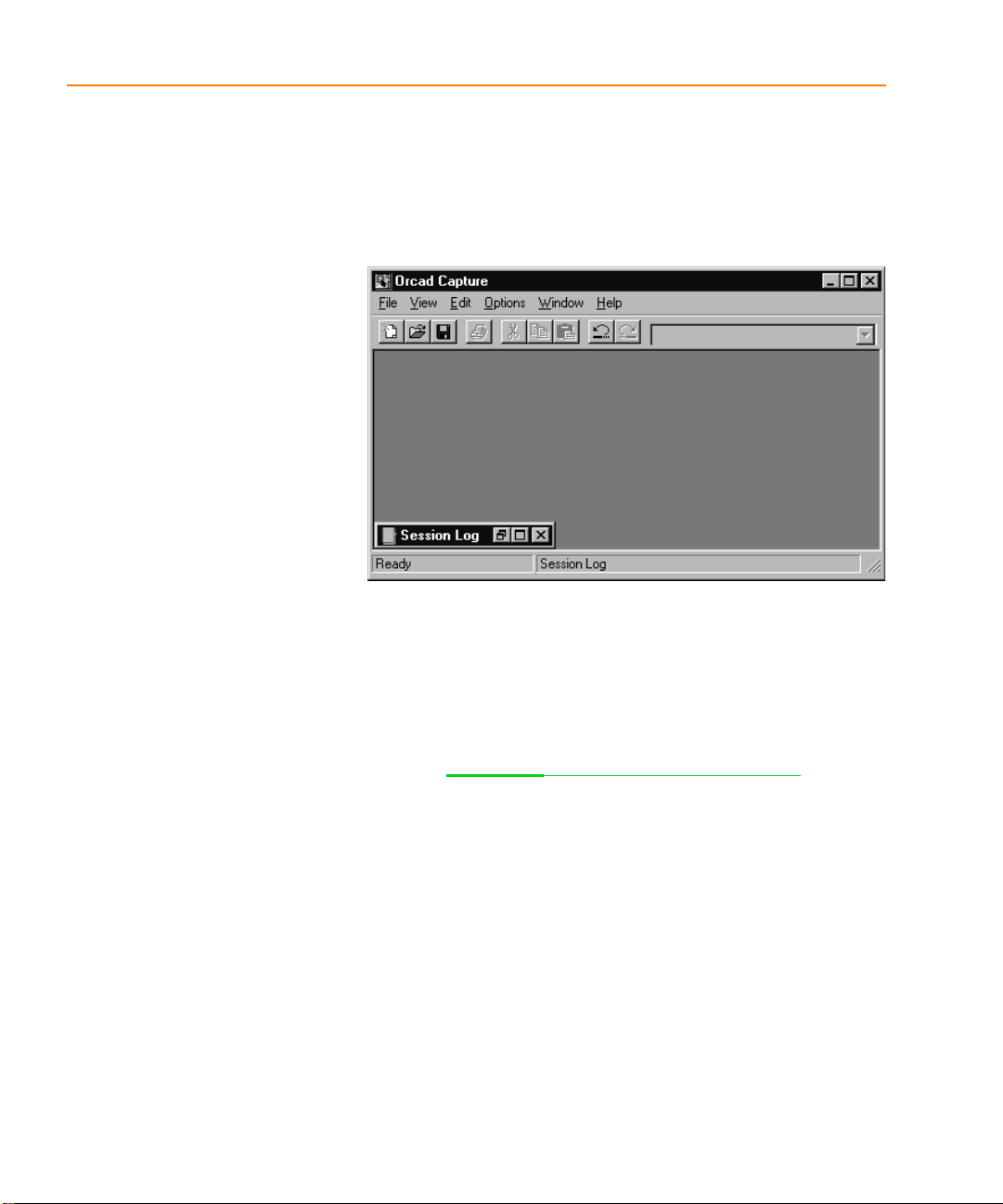
The Capture session frame
Once you start Capture, you see the Capture session frame.
You do all your schematic design and processing within
this window.
Figure 1 Capture’s session frame
The minimized Session Log icon in the lower left portion
of the Capture session frame is the sessi on log. The session
log provides information about everything you have done
in the current Capture session. Detailed information about
this window—and the other windows in Capture—is
given in Chapter 2,
In Capture, each design that you open is in a separate
project manager window. If you need to work
simultaneously with several designs, you can open them
all, and each will have its own project manager window.
Depending on which type of window you have active (an
active window is one whose title bar is highlighted),
certain buttons on the toolbar and certain items on the
menus may be unavailable, since you perform tasks and
use tools based upon the type of window that is active.
Also, the menus and menu choices vary, depending on
which type of window is active . The avail able me nus and
menu choices also vary depending upon the type of
project.
The Capture work environment.
4
Page 27

The Capture work environment
This chapter describes the things you need to know to find
your way around in Capture. It shows the windows you’ll
see in Capture: the project manager, the schematic page
editor, the part editor, the text editor, and the session log.
It also introduces you to the toolbar, tool palettes, and
general Capture concepts such as selecting and editing
objects, editing properties, and undoing and repeating
actions.
2
Page 28
Chapter 2 The Capture work environment
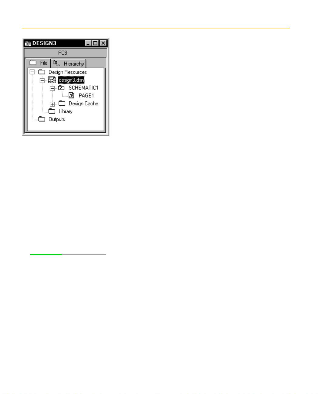
Figure 2 New project manager window
The project manager
You use the project manager to collect and organize all the
resources you need for your project. These resources
include schematic folders, schematic pages, part libraries,
parts, VHDL files, and output reports such as bills of
materials and netlists. Figure 2 shows a new project
manager window.
A project doesn’t actually contain all the resources. It
merely “points to” the various files that the project uses.
For this reason, be sure you don’t move or delete any f iles
referenced by a project. If you do, the project won’t be able
to find them.
The project file is saved with an .OPJ file extension. It is an
ASCII file, and can be viewed in any text editor.
Project manager folders
For information a bout hierarch ical designs ,
see Chapter 6,
6
Design structure.
The project manager provides a graphical display of a
project’s resources by grouping them into appropriate
folders, as described below.
• Shown underneath the Design Resources folder is the
design folder with the design’s schematic folders and
schematic pages, and a Design Cache folder that
shows all the parts used on the schematic pages.
Capture automatically adds any schematic folders or
schematic pages that you create to the design folder.
(In Figure 2, the design folder is named
DESIGN3.DSN.) You can add other files or
information using the Project command on the Edit
menu. For example, you can add an existing VHDL
file to the design folder and later attach the models
within that VHDL file to hierarchical blocks on a
schematic page.
Page 29

• The Library folder (in the Design Resources folder)
T
shows the schematic part library files you’ve add ed to
the project using the Project command on the Edit
menu.
• The Outputs folder shows the output of Capture’s
processing tools. Generally, these files include bill of
materials reports and technology-specific netlists.
Capture adds files to this folder when each is created.
The project manager
Each project may have only one design, but may have
multiple libraries. The design may consist of any number
of schematics or VHDL models, but it must have a single
root module. The root module is defined as the top level of
the design. That is, all other modules in the design are
referenced within the root module.
Within the project manager, you can expand or collapse
the structure you see by double-clicking on a folder, or by
clicking on the plus sign or minus sign to the left of a
folder. A plus sign indicates that the folder has contents
that are not currently visible; a minus sign indicates that
the folder is open and its c ontents are vis ible, liste d below
the folder. It appears as a schematic f older with a slash on
it in a design file, or as a page in a VHDL file.
Each project you open has its own project manager
window. You can move or copy folders or files between
projects by dragging them from one project manager
window to another (as well as to and from Windows
Explorer). To copy rather than move items, press and hold
C key while you drag them. If you close a project
the
manager window, you close the project.
ip The root module for a design has a
backslash in its folder icon, as shown in
Figure2 on page 2-6.
Note If a schematic page is open, you
cannot drag its icon to a different location.
In the project manager’s File tab, double-clicking on a
schematic folder expands it and displays icons for each
schematic page within the schematic folder. Then, if you
double-click on a schematic page icon, the schematic page
opens in a schematic page editor. Or, if the page is already
open, its window becomes active.
7
Page 30

Chapter 2 The Capture work environment
A design can consist of a single schematic page within a
single schematic folder, or a number of schematic pages
within a number of schematic fo lders. A s chemati c folder
contains schematic pages in a relationship similar to that
of a directory and the files it contains. Files are contained
in a directory; schematic pages are contained in a
schematic folder.
Note The project manager is also used to
manage libraries and the parts they
contain. This is covered in detail in
Chapter11, About libraries and parts.
A schematic page provides a graphical description of the
electrical connectivity of a design. It is made up of parts,
wires, and other electrical symbols. A schematic page may
also contain borders, title blocks, text, and graphics.
Capture acts on any schematic folders or schematic pages
you have selected within an active project manager
window. For example, the Find and Browse commands on
the project manager’s Edit menu, the Print command on
the project manager’s File menu, and the various tools on
the Tools menu only apply to the selected schematic folder
or page.
8
Page 31

Project manager tabs—File and Hierarchy
The project manager provides two ways to display a
project’s resources.
If you choose the File tab (shown in Figure 3), the project
manager displays all the project’s folders, schematic
folders, and schematic pages. These are displayed in a
tree-like fashion. You can expand or collapse the tree by
clicking the plus sign in front of the icon. When that
branch of the tree is expanded, the plus sign change to a
minus sign.
If you choose the Hierarchy tab (shown in Figure 4), the
project manager displays the hierarchical relationship
among the project’s schematic folders and schematic
pages.
For information abou t simple and complex hi erarchical
designs, see Chapter 6,
Design structure.
The project manager
Figure 3 File tab
Single view
In Capture v7.2 and earlier versions, Capture uses logical
view and physical view to separate instance and
occurrence information. In Capture Release 9 and later,
both instances and occurrences are together in a single
view. The project manager shows all occurrences in the
Hierarchy tab.
Capture v7.2 and earlier require you to change view
before creating a netlist for use with Orcad Layout. In
Capture Release 9 and later, the netlist tool provides an
option to use either the instance properties or the
occurrence properties for creating a netlist.
Figure 4 Hierarchy tab
9
Page 32

Chapter 2 The Capture work environment
Flat and hierarchical designs
In Capture, you can organize your schematics into flat or
heretical structures and interface to downstream EDA
products using either flat (popular for PCB layout) or
hierarchical (popular for synthesis and simulation)
netlists. The schematic system also supports reuse of
schematics within a hierarchy so you only need to draw a
schematic once, then instance it in multiple places for a
variety of applications. This guide uses the following
nomenclature to describe the parts and part properties of
these reused schematics:
Simple hierarchy. A hierarchical schematic design with no
reuse.
Complex hierarchy. A hierarchical schematic design with
reuse.
Part instance properties. The properties of any part that
has been placed in a schematic.
10
Part occurrence properties. The properties of a part that
make it unique from others in reused schematics.
Required to create a flat netlist with Capture.
Project manager pop-up menus
Several pop-up menus are available in the project
manager window. Pop-up menus are ava ilable by clicking
the right mouse button. You can use the commands on
these pop-up menus to open a file or schematic page, or
edit and view the properties of the currently selected item.
Page 33

The schematic page editor
In the schematic page editor, you can display and edit
schematic pages. You can place parts, wires, buses, and
draw graphics. The schematic page editor has a tool
palette that you can use to draw and place everything you
need to create a schematic page. You can print f rom within
the schematic page editor, or from the project manager
window.
The schematic page editor
Figure 5 Schematic page editor
11
Page 34

Chapter 2 The Capture work environment
The part editor
Create and edit parts using the part editor.
Figure 6 Part editor
From the View menu of the part editor, you can choose
Part or Package. In Part view you can:
• Create and edit parts and symbols, then store them in
new or existing libraries.
• Create and edit power and ground symbols, off-page
connector symbols, and title blocks.
For more information, see The part
editor tool palette on page 2-22.
See Chapter 11,
and parts for complete definitions of
parts and packages. See Chapter 12,
Creating and editing parts for a
complete description of the part editor.
12
About libraries
• Use the tool palette’s electrical tools to place pins on
parts, and its drawing tools to draw parts and
symbols.
Package view shows the entire package. A package is a
physical part that contains more than one logical part. You
can edit the properties of the entire package, such as part
reference, prefix, part alias, and so on. You cannot edit
individual parts in this view, but you can select individual
parts to edit by double-clicking on them.
The part editor is very similar to the symbol editor. The
main difference between the two is the symbol editor’s
lack of Pin and Pin Array tool palette buttons.
Page 35

The programmer’s editor
N
Use the programmer’s editor to create or view VHDL files
or other text files within Capture. VHDL keywords and
comments are displayed in the colors you specify. (From
the Options menu, choose Preferences and select the Text
Editor tab.)
Figure 7 Programmer’s editor
To create a new VHDL file in the programmer’s editor
1 From the File menu, point to New, then choose VHDL
File. A blank VHDL file appears in the text editor.
The programmer’s ed itor
To open a VHDL file in the programmer’s editor
1 From the File menu, point to Open, then choose VHDL
File. The Open VHDL File dialog box appears.
2 Select a file, then click OK.
Or
1 In the project manager, select a VHDL file.
2 Click the right mouse button, and choose Edit from the
pop-up menu.
oteDesigns and parts of designs can be
VHDL-based instead of schematic-based.
13
Page 36

Chapter 2 The Capture work environment
TipY
The session log
The session log lists the events that have occurred during
the current Capture session, including messages resulting
from using Capture’s tools. To display context-sensitive
help for an error message, put the cursor in the error
message line in the session log and press
The ruler along the top appears in either inches or
millimeters, depending on which measurement system
(U.S. or Metric) you have select ed in the Windows Control
Panel. You can add tab settings to the ruler by clicking in
the ruler bar and dragging the tabs to different positions,
or remove them by dragging them down into the session
log window. Capture saves your tab settings so that they
reappear each time you start Capture.
1.
ou can clear the session log by
choosing the Clear Session Log co mma nd ,
or by pressing
14
C+ X.
Figure 8 Session log
You can search for information in the session log using the
Find command on the Edit menu. You can also save the
contents of the session log to a file, which is u seful when
working with Orcad’s customer support staff to solve
technical problems. The default filename is SESSION.TXT.
Page 37

To display the session log
1 Click on the session log’s maximize button, or choose
Session Log from the Window menu.
To minimize the session log
1 Click the minimize button on the title bar.
To copy session log text to th e Clipboard
1 Select the session log window to make it active.
2 Select the text and choose Copy from the Edit menu.
To print the session log
1 Select the session log window to make it active.
2 From the File menu, choose the Print command.
To use Find in the session log
1 Select the session log window to make it active.
The session log
2 From the Edit menu, choose the Find command. The
Find dialog box appears.
3 Enter the word or words that you want to find.
4 Click Find Next.
To save the session log to a text file
1 Select the session log window to make it active.
2 From the File menu, choose the Save As command.
The Save As dialog box appears.
3 Enter a file name in the File name text box. By def ault,
the session log is saved to SESSION.TXT in the current
directory. If necessary, specify a new location for the
file.
4 Click Save. The session log text is saved to the file.
15
Page 38

Chapter 2 The Capture work environment
N
y
The toolbar
oteThe toolbar is always docked on the
top edge of the session frame the first time
ou open a project in a new session frame
of Capture. The position of the tool palet t e
is not saved.
Table 1 Tools on the Capture toolbar
Tool Name Description
New Create a new document based on the active document. Similar to the
New command on the File menu. For more information, see
new projects, designs, libraries, and VHDL files on page 3-52.
Open Open an existing project or library. Similar to the Open command on
the File menu. For more information, see
designs, libraries, and VHDL files on page 3-55.
Capture’s toolbar is dockable (that is, you can select an area
between buttons and drag the toolbar to a new location)
and resizable. By choosing a tool button, you can quickly
perform a task. If a tool button is dimmed, you can’t
perform that task in the current situation.
Figure 9 Capture’s toolbar
Some of the tools operate only on what you have selected,
while others give you a choice of either operating on what
is selected or expanding the scope to the entire project.
Table 1 summarizes the tools on the toolbar. The tasks that
these tools perform are described throughout this manual.
Creating
Opening existing projects,
Save Save the active document, schematic, or part. Equivalent to the Save
command on the File menu. For more information, see
Saving projects,
designs, and libraries on page 3-58.
Print Print the selected pages in the schematic folder, or the active schematic
page or part. Equivalent to the Print command on the File menu. For
more information, see
Cut Remove the selected object and place it on the Clipboard. Eq uivalent to
the Cut command on the Edit menu.
Copy Copy the selected object to the Clipboard. Equivalent to the Copy
command on the Edit menu.
Chapter 5, Printing and plotting.
16
Page 39

Table 1 Tools on the Capture toolbar (continued)
Paste Paste the contents of the Clipboard at the cursor. Equivalent to the
Paste command on the Ed i t me n u.
Undo Undo the last command performed, if possible. Equivalent to the Undo
command on the Edit menu.
Redo Redo the last command performed, if possible. Equivalent to the Redo
command on the Edit menu.
MRU Place a part or symbol from the list of most recently used parts and
symbols. For more information, see
Recently Used (MRU) List on page 7-120.
Zoom In Zoom in to see a closer, enlarged view. Equivalent to choosing Zoom
and In from the View menu. For more information, see
page 10-188.
Zoom Out Zoom out to see more of your document. Equivalent to choosing Zoom
and Out from the View menu. For more information, see
on page 10-188.
Zoom Area Specify an area of the schematic page or part to enlarge to fill the entire
window. Equivalent to choosing Zoom and Area from the View menu.
For more information, see
The toolbar
To place a part using the Most
To zoom in on
To zoom ou t
To view a selected area on page 10-189.
Zoom All View the entire document. Equivalent to choosing Zoom and All from
the View menu. For more information, see
To view the entire page or
part on page 10-191.
Annotate Assign part references to parts on the selecte d schematic pages.
Equivalent to the Annotate command on the Tools menu. For more
information, see
Back Annotate Back annotate the selected schematic pages. Equivalent to the Back
Annotate command on the Tools menu. For more information, see
Annotating on page 14-247 .
Back annotating on page14-266.
Design Rules
Check
Check for design rules violations on the selected schematic pages.
Equivalent to the Design Rules Check command on the Tools menu.
For more information, see
Checking for design rules violations on
page 14-256.
Create Netlist Create a netlist for the selected schematic pages. Equivalent to the
Create Netlist command on the Tools menu. For more information, see
Using the Create Netlist tool on page 15-271.
17
Page 40

Chapter 2 The Capture work environment
Table 1 Tools on the Capture toolbar (continued)
Cross Reference Create a cross reference report for the selected schematic pages.
Equivalent to the Cross Reference command on the Tools menu. For
more information, see
page 16-280.
Bill of Materials Create a bill of materials report for the selected schematic pages.
Equivalent to the Bill of Materials command on the Tools menu. For
more information, see
Snap-to-Grid Toggle schematic page and part editing to ei ther on or off grid.
Project Manager Di splay the project manager window for the active document,
providing an overview of project contents. Equivalent to choosing a
project manager window by number from the Window menu.
Help Topics Open online help. Equivalent to the Help Topics command on the
Help menu.
Creating a cross reference report on
Creating a bill of materials on page 16-275.
18
Displaying or hiding the toolbar
You can hide the toolbar, then display it again when you
need it.
To display or hide th e toolbar
1 From the schematic page editor’s View menu, choose
Toolbar.
or
From the part editor’s View menu, choose Toolbar.
Page 41

The tool palettes
Capture has two tool palettes: one for the schematic page
editor and one for the part editor. Both tool palettes are
dockable (that is, you can click on an area between buttons
and drag a tool palette to a new location) and resizable.
While the drawing tools on the two tool palettes are
identical, each tool palette has different electrical tools.
After you choose a tool (and, in the case of some tools,
after you respond to the tool’s dialog box), click the right
mouse button to display a context-sensitive pop-up menu.
The schematic page editor tool palette
The first group of tools on the tool palette is electrical
tools, used to place electrical connectivity objects. The
second group is drawing tools, used to create graphical
objects without electrical connectivity.
The tool palet te s
Note The tool palette is always docked on
the right edge of the session frame the first
time you open a schematic page or part in
a new session of Capture. The position of
the tool palette is not saved.
Figure 10 Schematic page editor tool palette
Table 2 describes the tools on the schematic page editor
tool palette.
For information on using the electrical
tools, see Chapter 7,
editing, and conne cting parts and
symbols. For information on how to use
the drawing tools, see Chapter 8,
Adding and editing graphic s and
Placing,
19
Page 42

Chapter 2 The Capture work environment
Table 2 Tools on the schematic page editor tool palette
Tool Name Description
Select Select objects. This is the normal mode.
Part Select parts from a library for placement.
Equivalent to the Part command on the Place
menu. For more information, see
Placing parts on
page 7-118.
Wire Draw wires. Press and hold
non-orthogonal (not a multiple of 90°) wires.
Equivalent to the Wire command on the Place
menu. For more information, see
S to draw
Placing wires on
page 7-149.
Net Alias Place aliases on wires and buses. Equivalent to the
Net Alias command on the Place menu. For more
information, see
Bus Draw buses. Press S to draw
non-orthogonal segments. Equivalent to the Bus
command on the Place menu. For more
information, see
Junction Place junctions. Equivalent to the Junction
command on the Place menu.
Bus Entry Draw bus entries. Equivalent to the Bus Entry
command on the Place menu. For more
information, see
Placing buses on page 7-152.
Placing buses on page 7-152.
Placing bus entries on
page 7-153.
Power Place power symbols. Equivalent to the Power
command on the Place menu. For more
information, see
Placing power and ground
symbols on page 7-128.
20
Ground Place ground symbo l s. Equivalent to the Ground
command on the Place menu. For more
information, see
Placing power and ground
symbols on page 7-128.
Page 43

Table 2 Tools on the schematic page editor tool palette (continued)
The tool palet te s
Hierarchical
Block
Place hierarchical blocks. Equivalent to the
Hierarchical Block command on the Place menu.
For more information, see
Placing hierarchical
blocks on page 7-134.
Hierarchical
Port
Place hierarchical ports on schematic pages.
Equivalent to the Hierarchical Port command on
the Place menu. For more information, see
Placing
hierarchical ports on page 7-139.
Hierarchical
Pin
Place hierarchical pins in hierarchical blocks.
Equivalent to the Hierarchical Pin command on
the Place menu. For more information, see
Placing
hierarchical pins on page 7-141.
Off-Page
Connector
Place off-page connectors. Equivalent to the
Off-Page Connector command on the Place menu.
For more information, see
Placing off-page
connectors on page 7-144.
No Connect Place no-connect symbols on pins. Equivalent to
the No Connect command on the Place menu. See
Placing and editing no-connect symbols on
page 7-132.
Line Draw lines. Equivalent to the Line command on
the Place menu. For more information, see
Drawing lines on page 8-159.
Polyline Draw polylines. Press and hold S to draw
non-orthogonal polylines. Equivalent to the
Polyline command on the Place menu. For mo re
information, see
Drawing polylines and polygons
on page 8-163.
Rectangle Draw rectangles. Holding
square. Equivalent to the Rectangle command on
the Place menu. For more information, see
S constrains t o a
Drawing rectangles and squares on page 8-160.
Ellipse Draw ellipses. Holding
to a circle. Equivalent to the Ellipse command on
the Place menu. For more information, see
S constrains shape
Drawing circles and ellipses on page 8-161.
21
Page 44

Chapter 2 The Capture work environment
Table 2 Tools on the schematic page editor tool palette (continued)
Arc Draw arcs. Equivalent to the Arc command on the
Place menu. For more information, see
Drawing
arcs on page 8-162.
Text Place text. Equivalent to the Text command on the
Place menu. For more information, see
Placing
text on page 8-168.
The part editor tool palette
The first group of tools on the part editor tool palette are
electrical tools, used to place pins and IEEE symbols. The
second group of tools are drawing tools, used to create
graphical objects without electrical connectivity.
For information on how to use the electrical
tools, see Chapter 12,
Creating
and editing parts. For information on
how to use the drawing tools, see
Chapter 8,
Adding and editing
Table 3 Tools on the part editor tool palette
Tool Name Description
22
Figure 11 Part editor tool palette
Table 3 describes the tools unique to the part editor tool
palette. The drawing tools are described in the previous
section, The schematic page editor tool palette on page 2-19
IEEE
Symbol
Place IEEE symbols on a part. Equivalent to the
IEEE Symbol command on the Place menu. For
more information, see
Adding graphics, text, and
IEEE symbols to a part on page 12-217.
.
Page 45

Table 3 Tools on the part editor tool palette (continued)
Pin Place pins on a part. Equivalent to the Pin
command on the Place menu. For more
information, see
Placing pins on a part on
page 12-218.
Pin Array Place multiple pins on a part. Equivalent to the
Pin Array command on the Place menu. For more
information, see
Placing pins on a part on
page 12-218.
The tool palet te s
23
Page 46

Chapter 2 The Capture work environment
Displaying or hiding a tool palette
Like the toolbar, you can hide a tool palette, then display
it again when you need it.
To display or hide a tool pa le tte
1 From the schematic page editor’s View menu, choose
Tool Palette.
or
From the part editor’s View menu, choose Tool
Palette.
24
Page 47

The status bar
N
The status bar, located at the bottom of the Capture
session frame, reports on current actions, number of items
selected, zoom scale, and pointer location.
Figure 12 The status bar
Left field
The left field displays descriptions of selected tools or
menu items, prompts, or the current status.
Center field
The status bar
The center field displays the number of items selected in
the schematic page editor or part editor.
oteWhen a session log or a project
manager window is active, the center field
of the status bar doesn’t display.
Right field
The right field displays the current scale and pointer
location (such as: Scale=50% X=10.0 Y=5.0). The location
in the schematic page editor is measured in either inches
or millimeters, depending on the Units settings in the
Schematic Page Properties dialog box (Page Si ze tab). The
pointer location in the part editor is measured in grid
units.
25
Page 48

Chapter 2 The Capture work environment
Displaying or hiding the status bar
You can hide the status bar, then display it again when
you need it.
To display or hide the status bar
1 From the schematic page editor’s View menu, choose
Status Bar.
or
From the part editor’s View menu, choose Status Bar.
26
Page 49

Selecting and deselecting objects
g
T
Selecting and deselecting objects
Once you select an object, you can perf orm operati ons on
it, including moving, copying, cutting, mirroring,
rotating, resizing, or editing. You can also select multiple
objects and edit them, or group them into a single object.
Grouping objects maintains the relationship among them
while you move them to another location.
This section describes different ways to select individual
objects and groups of objects in both the schematic page
editor and the part editor.
To select an object
1 Position the pointer on the object and click the left
mouse button. The object displays in the selection
color.
To reset the selection color
1 From the Options menu, choose Preferences, then
select the Colors tab.
2 Click the left mouse button on the Selection color.
3 Click to select a color from the Selection Color
window, then click OK. Click OK again to dismiss the
Preferences dialog box.
Note You can edit the properties of a
roup of objects using the property editor.
See The property editor on page 34.
To select multiple objects
1 For each object to select, position the pointer on the
object and hold
button. Every object in the selection set displ ays in the
selection color.
C while you click the left mouse
ip To select a part, click within the part
itself. To select a graphical object, zoom in
and click on an outside edge of the object.
To deselect objects
1 Click on the schematic page away from any objects.
Selected objects beco me deselected. Keep i n mind that
a part occupies a rectangular area encompassing all its
graphics. This means that a part may occupy a larger
area than is initially apparent.
27
Page 50

Chapter 2 The Capture work environment
N
y
To select all objects i n an area
1 From the tool palette, choose the selection tool.
2 Click on an area away from any objects or parts to
deselect any items that may be selected.
3 Move the pointer to one corner of the area to select.
Press and hold the left mouse button while you drag
the mouse to the opposite corner, then release the left
mouse button. Every object in the selection set appears
in the selection color.
To include or exclude objects intersected by yo ur selection
rectangle
1 From the Options menu, choose Preferences.
2 On the Select tab, select one of the Area Select options.
You can choose Intersecting to include items that are
not fully enclosed by your selection rectangle, or
choose Fully enclosed to exclude items that were not
entirely selected.
To select all objects on a schematic page or part
1 From the Edit menu, choose Select All. All objects
appear in the selection color.
oteA selection set behaves as if it is one
object, so you can move, copy, cut, delete,
mirror, or rotate the entire set. Be aware,
however, that the Select All command also
selects the title block on the schematic
page. If you copy or move the selectio n set,
ou could create a duplicate title block, or
inadvertently move the title block off the
schematic page.
28
To select an obje ct from a set o f object s stacke d atop o ne anoth er
1 Position the pointer over the stack of objects.
2 Press
F while you click the left mouse button. This
cycles through the objects in the stack.
To remove one object from a selection set
1 Place the pointer over the object, press C, and click
the left mouse button.
Page 51

Grouping objects
Use the Group command on the Edit menu to group
multiple objects into one selectable object. This is a
convenient way to maintain the relationship among
several objects while moving them to another location.
You can nest groups, meaning a group can contain other
groups as well as objects.
The Group command is only available when multiple
objects are selected. Objects remain grouped until you
ungroup them or close the schematic page or part that
contains the m.
To group multiple selected objects
Selecting and deselecting objects
1 Select the objects you want to group. (See Selecting a nd
deselecting objects on page 2-26 for more information).
2 From the Edit menu, choose Group. You can move the
objects as a group.
3 When have finished working with the objects as a
group, you can ungroup them. From the Edit menu,
choose Ungroup.
Caution The Group command will not be
available if your selection includes a net
alias (a property). Afte r block select ing the
objects you want to group, desel e ct the
included net aliases by holding the
key and clicking on each object.
C
29
Page 52

Chapter 2 The Capture work environment
Editing properties
In a Capture schematic design, each object has properti es
that define their characteristics. These objects include:
• Parts (including hierarchical blocks)
• Nets (including constituent nets within buses)
• Pins
• Globals
• Aliases
• Hierarchical ports
• Off-page connectors
• DRC markers
• Bookmarks
• Title block
A property consists of a property name (for example , Part
Value or Part Reference) and an associated value (for
example, TIP31C or Q2). For example, part properties
define the name, value, reference designator, and other
information for each part in your design.
30
In Capture you can edit property values, create or delete
properties, or cause the properties to be displayed on the
schematic page.
Use one of three editors to edit properties:
• The Browse spreadsheet editor, as described on
page 2-31
• The property editor, as described on page 2-34.
• The Package Properties spreadsheet editor, as described
.
on page 45.
Page 53

Instance and occurrence properties
Since Capture allows for complex hierarchical design
structures (as discussed in Chapter 6,
each of the objects listed above can exist as instances or
occurrences.
In complex hierarchical designs, a schematic page can be
referenced (or reused) at several points in the design. An
instance refers to the object that is placed on the defining
schematic. An occurrence represents the use or reuse of
that instance within a design. When you edit properties
for an object, you can edit the instance, or you can edit a
particular occurrence of that instance.
Instance properties
An instance property is a user property applied to the
placed instance of a part or symbol in the design. This
includes PCB Footprint, Value, and Name properties of
each placed part or symbol in a design. The instance
property overrides the library definition.
Design structure),
Editing properties
An instance property will “shine through” to all
occurrences of that instance unless it is overridden by
occurrence properties. A change using any of the tools,
like Annotate, also may update the instance property.
Occurrence properties
An occurrence property is a user property applied to
multiple occurrences of place instances of parts or
symbols in a design. The occurrence property overrides
the instance property definition.
The spreadsheet editors expand to display occurrence
properties if values are different from the instance value.
To quickly hide or display all the occurrence properties,
press and hold the
plus (+) symbols in the property editor.
A change using any of the tools, like Annotate, also may
update the instance property.
C key while clicking on one of the
31
Page 54

Chapter 2 The Capture work environment
The Browse spreadsheet editor
You display the Browse spreadsheet editor from the
project manager’s Edit menu, the schematic page editor,
or the part editor. The particular Browse spreadsheet that
you display depends on the object you select from the
Browse pull-right menu. The options include:
• Hierarchical ports
Figure 13 Browse spreadsheet editor
• Off-page connectors
• DRC markers
• Bookmarks
• Part (including hierarchical block) occurrences
• Net (including constituent nets within a bus)
occurrences
• Pin properties
• Title block occurrences
• Flat nets
The Browse spreadsheet editor browses the entire design
for the objects you select, then displays their properties.
Each property appears as a column heading in the
spreadsheet. Each row is an object located by the editor.
It is important to note that, in the Browse spreadsheet
editor you can only edit properties for occurrences. The
only exception being in the part editor, where you can
only edit instances. To edit instance properties, you must
use the property editor discussed in The property editor on
page 2-34.
32
Page 55

To create a new property in the Browse spreadsheet editor
1 In the first column of the Browse spreadsheet, select
the object or occurrence for which you want to create
the new property.
2 From the Edit menu, choose Properties. Capture
displays the object in a new Browse spreadsheet
window.
3 Click New. Capture displays the New Property dialog
box.
4 Enter a name and value for the new property, then
click OK. Capture adds the property to the object or
occurrence and displays the new prope rty in the
original Browse spreadsheet.
To copy a value from one prop erty to another proper ty in the
Browse spreadsheet editor
1 In the first column of the Browse spreadsheet, select
the object or occurrence that has the property with the
value you want to copy.
Editing properties
2 From the Edit menu, choose Properties. Capture
displays the object in a new Browse spreadsheet
window.
3 Select the cell that contains the value you want to
copy.
4 Click Copy.
5 Select the cell that you want to contain the copied
value.
6 Click Paste. Capture pastes the value into the selected
cell.
33
Page 56

Chapter 2 The Capture work environment
To remove a user-defined property in the Browse spread sheet
editor
Note Some properties cannot be r emoved
as they are essential for creating a netlist.
You can only remove user-defined
properties.
Note If you remove a property from an
occurrence for which there is a defined
instance property, the occurrence property
is not removed, but rather, th e instance
property value “shines through” to the
occurrence. In order to remove an instance
property you must use the property editor.
For more information about instance and
occurrence properties see The property
editor on page 2-34.
1 In the first column of the Browse spreadsheet, select
the object or occurrence that has the property you
want to remove.
2 Select the column heading for the property you want
to remove.
3 Click Remove. Capture removes that property from
the object.
To replace property values
1 Select the objects whose properties you want to edit.
Note that the objects must be of the same type (for
example, all pins or all hierarchical ports); otherwise,
the Properties command is grayed out.
2 From the Edit menu, choose Properties. The Browse
spreadsheet appears.
3 Double-click on a cell holding the value you wish to
replace, then enter the new value.
4 Click the copy button.
5 Select the cells that are to receive the replacement
value.
34
6 Click the Paste button. The replacement value appears
in the selected cells.
7 Click the OK button to close the Browse spreadsheet.
Page 57

The property editor
You display the property editor either by selecting items
on a schematic page, then choosing Properties on the Edit
or popup menu, or by simply double-clicking on an item
in the schematic page editor.
The property editor allows you to edit properties for
instances or occurrences of the following objects:
• Parts (including hierarchical blocks)
• Nets (including constituent nets within buses)
• Pins
• Title blocks
Editing properties
• Globals
• Ports
• Aliases
The property editor is constrained such that it can only
edit instances or occurrences on the active schematic page.
To browse and edit properties for an entire design, see The
Browse spreadsheet editor on page 2-31.
Note Globals are power and ground
symbols, or any other objects that behave
like power and ground.
35
Page 58

Chapter 2 The Capture work environment
The property editor window
Note When you first st a rt the property
editor all instance proper ties are displayed.
Occurrence properties are displayed only if
they have their own values assigned to
them (independent of the instance property
values).
The properties that appear in the property editor depend
on the items selected in the schematic page. Also, these
properties depend on the tab selection at the bottom of the
property editor. For example, if the Parts tab is active, the
properties for selected parts appear in the property editor.
Occurrence
hierarchical path:reference
Instance name
schematic name:page:reference
Property names
Item selection tabs
Filter drop-down list
Property value
36
Figure 14 Property editor
Each column in the property editor is a placeholder that
you can use to add properties.
Each row is an instance or occurrence. Occurrence rows
appear in yellow below their associated instance row.
They only appear if one or more occurrence property
values are different from the instance property values and
you expand the instance by clicking the plus sign (+) to the
left of the instance name.
The cells in the property editor show th e property values
for each instance or occurrence. If a white cell contains a
cross-hatch pattern, the corresponding property does not
have an instance value, causing the library definition to
“shine through” to the instance. If a yellow cell contains a
Page 59

cross-hatch pattern, the corresponding property does not
N
have an occurrence value, causing the instance property
value to “shine through” to the occurrence.
New Column or New Row Displays the Add New
Column dialog box or the Add New Row dialog box,
depending on the property editor orientation. These
dialog boxes add a new property column or row,
respectively. To add the property to an object, you must
enter a property va lue for the object.
Apply Applies the changes in the property editor to the
schematic page. The Apply button does not dismiss the
property editor. You can also apply the changes to the
schematic page by closing the property editor.
Display Opens the Display Properties dialog box to se t
the display options of the selected property and its value.
You cannot display properties of an occurrence property
using the Display Properties dialog box.
Editing properties
oteYou can pivot the property editor
spreadsheet. Instances and occurrences
appear in columns across the top and
properties appear in rows. This may be
advantageous if your selected object or
objects have several properties. See To
pivot the property editor
spreadsheet on page 2-38.
Delete Property Deletes the property, if editable, from
the selected object or objects. If you select all of a
property’s cells and click the Delete Property button, the
property will be removed from the selected objects but
will remain in the filter. This is indicated by the
cross-hatch pattern that appears in the cell.
Note Properties that are not editable
appear in italics.
Filter by Specifies a filter by which you can view
objects. Use the filters available in the drop-down list to
constrain the available properties. Each filter is a set of
properties that are typically useful for particular project
types. For example, the Actel Designer Part/Net
Properties filter includes properties that are useful for
constraining a PLD project for integration with Actel’s
Designer software. The Capture filter displays common
schematic capture properties available to most parts. The
Layout filter displays properties needed to send a design
to Orcad Layout. The <Current properties> filter causes
37
Page 60

Chapter 2 The Capture work environment
the property editor to display all properties that currently
exist for the selected item. For more information, see The
property editor Filter menu on page 2-39.
Parts tab Displays the parts of the selected objects,
including hierarchical blocks.
The Graphic property column provides the option to
toggle the display of the part between Normal and
Convert view. When you click the Graphic cell, a down
arrow indicates a drop-down list where you can select a
different view.
Schematic Nets tab Displays the schematic nets of the
selected objects, inclu ding constituent nets within buses.
Pins tab Displays the pins of the selected objects,
including hierarchical pins in hierarchical blocks.
38
Title Blocks tab Displays the title blocks of the
selected objects. With this tab, you can add a property to
the Title Block instance on a schema tic page that di splay s
the full hierarchical path to the schematic.
Globals tab Displays selected globals for simultaneous
editing of multiple names.
Ports tab Displays the source symbol, source library,
and type of port. This tab provides for simultaneous
editing of multiple ports.
Aliases tab Displays color, font, name, and rotation of
net aliases. Use this tab to edit multiple alia ses at one time.
Page 61

To pivot the property editor spreadsheet
1 Right-click the empty cell in the top-leftmost position
of the spreadsheet.
2 From the pop-up menu, choose Pivot.
To display or hide all occurrence properties
1 To display all occurrence properties, press and hold
C key while clicking on one of the plus (+)
the
symbols in the left-most column.
2 To hide all occurrence properties, press and hold the
C key while clicking on one of the minus (-) symbols
in the left -most colu mn.
To move columns in the property editor
Editing properties
Note The Find command searches down
columns in the spreadsheet, regardless of
the spreadsheet orientation.
1 Select the column you want to move by clicking on its
title cell.
2 Drag the column to the new location.
To sort columns in the property editor
1 Right-click on the column heading. A pop-up menu
appears.
2 Choose Sort Ascending or Sort Descending.
Note If the spreadsheet is pivoted, use
these steps to move rows.
39
Page 62

Chapter 2 The Capture work environment
The property editor Filter menu
The property editor filter is a powerful tool with which
you can show or hide properties on selected objects. You
can use the pop-up Filters menu on the spreadsheet to
view the status of a property or edit columns, tabs, or the
entire property editor spreadsheet.
You can add, delete, or change any filter except the
<Current properties> filter. The <Current properties>
filter displays all properties as undefined until you crea te
or select another filter.
When you create a new filter, all properties appear
undefined, just as in the <Current properties> filter. If you
right-click a column heading and select Filters from the
pop-up menu, you will see that each property is
Undefined, and the filter specifies Show Undefined.
Your results will be more reliable if you use the property
editor Filters menu to make changes rather than editing
the PREFPROP.TXT file manually.
Changes to the filters are saved to PREFPROP.TXT when
you close the spreadsheet. If you need to retrieve the
original version, you can copy PREFPROP.TXT from the
Orcad installation CD in the Captur e directory.
The first four choices on the Filter menu apply to the
appearance of a particular tab and column.
Show The selected column always appears when you
use the filter, unless the filter is inverted.
Hide The selected column never appears when you use
the filter, unless the filter is inverted.
Optional The selected column only appears if the
property exists on one or more objects when you use this
filter.
40
Page 63

Undefined The selected property is not defined. It isn’t
included or excluded from the filter.
You can control the display of undefined properties on
individual tabs with the next two choices on the Filter
menu. Select any combination of the two.
Show Undefined Sp ecifies that any undefin ed
property columns that are selected appear when you use
the filter. However, if you also select Invert Filter, these
same selections will not appear.
Defined properties appear at the beginning of the
spreadsheet (toward the left side) when you select this
option.
Invert Filter Shows hi dden property col umns when
you use the filter. Conversely, it will hide any property
columns that you have specified to show. For example, if
a property is optional and does not exist on any objects,
you can use Invert Filter to show the property.
Editing properties
The last two choices on the Filter menu affect all tabs on
the property editor.
Add Filter Add a new filter to all tabs. The default of a
new filter is to show all properties as undefined
Remove Current Filter Delete the filter currently
displayed in the Filter by list box. You cannot undo this
operation.
41
Page 64

Chapter 2 The Capture work environment
To create a new filter in the prope rt y edit or
1 Right-click any column heading in the spreadsheet.
2 Point to Filters in the pop-up menu and choose Add
Filter.
3 Type the new filter name in the Add Filter dialog box
and click OK. The new filter is saved in
PREFPR OP.TXT wh en you close the property editor.
To edit a filter
1 Select a filter from the Filter by drop-down list. The
appearance of the properties on the spreadsheet may
change when you change the filter.
2 Right-click any column heading and point to Filters in
the pop-up menu.
3 Use the Filters menu choices to change the property
definitions and appearance of the spreadsheet.
42
Page 65

Using the property editor
When editing properties in the property editor, it is
important to remember a few key points:
• Property values that are applied to instances will
“shine through” to all occurrences of those instances,
unless an occurrence has a value (independent of the
instance value) for a particular property.
• Occurrence property values override instance
property values.
• When you delete an instance property, that property
will no longer “shine through” to its occurrences.
• Deleting a property value from an occurrence causes
the instance property value to “shine through” to that
occurrence.
• Library definitions will “shine through” to the
instance and occurrence of the object only if the
instance or occurrence value is unedited.
Editing properties
To create a new property in th e property editor
1 In the schematic page editor, select the object(s) for
which you want to create the property.
2 From the Edit menu, choose Properties. Capture
displays the property editor.
3 Click the New Column or the New Row button.
Capture displays the Add New Column dialog box or
the Add New Row dialog box.
4 Enter a name for the new property and click OK.
Capture adds the new property to the property editor
and to all instances and occurrences currently
displayed therein.
5 Enter values for the property as described in To edit a
property value in the property editor.
43
Page 66

Chapter 2 The Capture work environment
Note Some property values (t hose that
have particular significance to th e design
database) cannot be edited. Properties that
are not editable appear in italics.
To edit a property val u e in th e property editor
1 In the property editor, select the cell that contains the
value you want to change.
2 Right-click and choose Edit from the pop-up menu.
The Edit Property Values dialog box appears.
3 Type in the new value and press
changing an instance property value causes that value
to “shine through” to all occurrences of the instance
that do not have a value independent of the instance.
R. Note that
To edit the a property value for all instances and occurrences
currently displayed in the property editor
1 In the property editor, click the top-leftmost cell to
select the entire spreadsheet.
2 Right-click and choose Edit from the popup menu.
3 Select a property cell in the Edit Property Value dialog
box spreadsheet.
4 Type the new value for the property and click OK. The
new property value appears on the spreadsheet for all
selected objects.
Note Some property values (t hose that
have particular significance to th e design
database) cannot be deleted.
44
To delete a property in the property editor
1 Select the column of the property you want to delete.
2 Click the Delete Property button. The property is
removed. (The property column remains in the
display. To see that the property is deleted, leave the
property editor and then return to it.)
Page 67

To display a property on the schematic page
Editing properties
1 In the property editor, select the instance property
cells you want to display, then click the Display
button. Capture displays the Display Properties
dialog box.
2 Complete the dialog box as desired, then click OK.
Capture displays the property on the schematic page
for all instances currently displayed in the property
editor.
For information on the Display Properties
dialog box, see the Capture online help.
Note Although you can only set the display
for instances, the property value that
appears on the schematic page is that of the
particular occurren ce.
45
Page 68

Chapter 2 The Capture work environment
The Package Properties spreadsheet editor
You can edit package properties using the Package
Properties spreadsheet editor. The Package Properties
spreadsheet editor is available in the part editor while in
Package View. Use the Properties command on the Edit
menu to display this spreadsheet. The spreadsheet
displays all the package information on pins.
46
Figure 15 Package Properties spreadsheet edi to r
The Package Properties spreadsheet editor is simi lar to the
Browse spreadsheet editor with the following differences:
• The Package Properties spreadsheet editor doesn’t
have New or Remove buttons. You cannot add
properties to a package or remove existing properties.
• The Package Properties spreadsheet displays all of the
pins in the package, regardless of what is selected in
the part editor.
• The Package Properties spreadsheet displays the
PinGroup and Ignore properties. These do not show
up in the Browse spreadsheet editor.
• The Package Properties spreadsheet has an Update
button and a Validate button.
Page 69

Update button Use this to update the properties of all
the pins in the package. This is useful if you change a
property on one pin and need to change this property on
the same pin in the other parts of the package. For
example, say you have a four-part package and each part
in the package has a pin named IN. If you c hange this pin
from a passive pin to an input pin the A package part, you
could use Update to change the property for the IN pin in
the B, C, and D package parts. The Update butt on updates
all pins at once, without requiring that you click OK.
Validate button Use this button to check for duplicate
pins. For example, suppose you have a pin 1, and then
change another pin to pin 1. Using Validate detects th e
duplicate. The Validate button checks for duplicate pin
numbers without requiring that you click OK.
Editing properties
47
Page 70

Chapter 2 The Capture work environment
Note For description s of ot her ways to
manipulate objects, see Chapter 8, Adding
and editing graphics and text.
Moving and resizing graphic objects
For some objects—such as wires, buses, lines, ellipses,
rectangles, and so on—you can edit the object’s size and
shape by clicking on it and dragging its resize handles.
Before you can move or resize a graphic object, you must
first select it. A selected object has resize handles that you
use to change the size of the graphical object.
To resize and move objects
1 Select the object to resize or move.
2 To resize the object, press the left mouse button on a
resize handle, and drag the handle until the object is
the size you would like it. Release the mouse button.
or
To move the object, press the left mouse button
anywhere on the object—except on a resize handle—
and drag the object until it is where you want it.
Release the mouse button.
48
3 To deselect the object, clic k i n an area whe re there a re
no parts or objects.
Page 71

Undoing, redoing, and repeating
T
an action
You use the Undo command to undo your action. To
repeat an edit action, use the Repeat command. For
example, you might move a selected object five grid units,
then realize you also need to move a different object the
same distance. Select the second object, then from the Edit
menu, choose the Repeat command. You can use the
Undo, Redo, and Repeat commands with the following
actions:
• Placing objects
• Deleting objects (except for the Repeat command)
• Copying objects
• Moving objects
• Resizing objects
Undoing, redoing, and repeating an action
• Rotating objects
• Mirroring objects
To undo an action
1 From the Edit menu, choose Undo.
To reverse an undone acti on
1 From the Edit menu, choose Redo.
To repeat a command
1 Perform the command once.
2 From the Edit menu, choose Repeat.
ip You can use the R e peat command to
align objects or to quickly create repetitive
structures such as buses.
49
Page 72

Chapter 2 The Capture work environment
To repeat a copy operation
1 Select an object on a schematic page.
2 Press
3 From the Edit menu, choose Repeat. The pointer
C and drag the object to a new location. This
creates a copy of the object. Leave the object selected.
repeats the relative move in step 2 and an additional
object is placed.
50
Page 73

Using the Accessories menu
You can use extensions to the Orcad-supplied
functionality of Capture if you purchase software
developed by associates of Orcad. These associ ates create
.DLL files that address specific Capture functionality,
such as customized netlist creation. The associates
configure their .DLL files so that they are listed as menu
choices on the Accessories menu, available in either the
project manager window or the schematic page editor
window.
Using the Accessories menu
51
Page 74

Chapter 2 The Capture work environment
52
Page 75

Starting a project
w
3
A project file (.OPJ) stores pointers to a single design file
(.DSN), and can also contain libraries, VHDL files, and
output reports associated with the design file. A design
file contains one or more schematic folders, in which there
are one or more schematic pages. A design file also
contains a design cache, which is like an embedded
library
used on the schematic pages. When a design is saved with
the project file, information from the various Tools dialog
boxes is also saved in the project file.
—it contains a copy of all the parts and symbols
Note Parts reside in a library the same
ay schematic pages reside in schematic
folders. Symbols and title bl ocks also reside
in libraries. A project can use any number
of libraries, and a library can be in cluded in
any number of projects. However, a project
may have only one design (.DSN).
Page 76

Chapter 3 Starting a project
w
y
Creating new projects, designs, libraries, and VHDL files
Capture includes a project wizard that provides an easy
method for creating a project, complete with library and
simulation resources.
Creating a project does not create a design within the
project. A new design inherits characteristics from the
settings in the Design Template dial og box, so you should
always check those settings before you create a design.
A newly created project contains a schematic folder that
holds one schematic page. After you create a schematic
folder, you can move existing pages into it, and you can
create new pages in it.
Libraries store parts, symbols, custom title bl ocks, as well
as schematic folders and the schematic pages cont ained in
them. With Capture, you can have as many libraries as
you wish to suit any purpose, and you can specify the
name and storage location of your library. Each library is
available to each project.
To create a new project
1 From the File menu, choose New, then choose Project.
The New Project dialog box appears.
2 Type a name for your new project in the Name text
box.
3 Use the Browse button to select a new directory.
Note The project types available to you
ill depend upon which Orcad programs
ou have installed. As a minimu m, you will
have the option to create a PC Board o r
Schematic project type.
52
4 Select a project type in the Create a New Project Using
group box, and click OK. Capture provides the
following project types:
• Analog or mixed signal circuit—select this type of
project if you intend to use your design with
PSpice. Follow the guidance of the Analog
Mixed-Mode Project wizard to add the
appropriate files to your project.
Page 77

• PC board—select this type of project if you intend
y
to use your design with Orcad Layout. Follow the
guidance of the PCB Project Wizard to add the
appropriate files to your project.
• Programmable logic—select this type of project if
you intend to use your design with an FPGA or
CPLD EDA tool. Follow the guidance of the
Programmable Logic Project Wizard to add the
appropriate files to your project.
• Schematic—select this type of project if none of the
other project types apply. Using this option,
Capture creates a basic project containing only the
design file.
To create a new design
1 From the File menu, choose New, then choose Design.
2 The design opens in a new PCB project manager and a
new schematic page displays.
The first time you save a new design, the Save As dialog
box appears, giving you the opportunity to specify a drive
and replace the system-generated name.
Creating new projec ts, designs, libraries, and VHDL files
Note A project cannot have more than one
design (.DSN) file. If you try to add a
second .DSN file to your project, the
Overwrite dialog box appears, asking if
ou want to replace the existing design.
To create a new schematic page
1 On the File tab of the project manager, select the
schematic folder that requires a new schematic page.
2 Click the right mouse button and choose New Page
from the pop-up menu. A new schematic page
appears within the schematic folder you selected in
step 1.
To create a new library
1 From the File menu, choose New, then choose Library.
2 The library opens in the project manager and a Library
Cache folder is added to the project manager, or the
library opens in the existing open project manager and
a library cache is added.
For information on how to create p arts for
inclusion in a library, see Chapter 12,
Creating and editing parts.
53
Page 78

Chapter 3 Starting a project
To create a new VHDL file
There are two ways to create a new VHDL file in Capture:
1 From the File menu, choose New, then choose VHDL
File.
2 A VHDL file opens in Capture’s VHDL programmer’s
editor.
Or
1 With the project manager active, choose New VHDL
File from the Design menu. The file opens in the
VHDL programmer’s editor and a dialog box appears,
asking if you want to add the file to the project.
Note If you choose the No button, Capture
does not add the VHDL file to your project
and you must save it yourself at a later
point in time.
2 Choose the Yes button to add the file to the project that
is currently open. The Save As dialog box appears.
3 Select a directory for the file and supply a filename. By
default, the VHDL file’s name is VHDLn.VHD (where
n is an integer indicating the number of .VHD files
created in the curre nt session).
4 Choose the Save button. Capture saves the file and
places it in the Design Resources folder of your
project.
54
Page 79

Opening existing projects,
T
designs, libraries, and VHDL files
Opening existing projects, designs, libraries, and VHDL files
You can open an existing project, design, library or VHDL
file. Existing schematic pages can only be opened from
within designs and libraries.
To open an existing project
1 From the File menu, point to Open, then choose
Project. The Open Project dialog box displays.
2 Select a project (.OPJ) or type the name in the File
name text box, then choose the Open button. The
project opens in the project manager.
To open an existing design
1 From the File menu, point to Open, then choose
Design. The Open Design dialog box displays.
2 Select a design (.DSN) or type the name in the File
name text box, then choose the Open button. The
design opens in the project manager.
To open an existing schematic page
1 In the project manager, select the File tab and
double- click the ico n of a schem atic folder ; this
expands the folder and reveals the schematic pages it
contains.
ip The four files that were last opened are
listed at the bottom of the File menu. To
open one of these files, select it from the
File menu.
Figure 16 Open project, design, and
schematic page
2 Double-click on the icon of the schematic page you
want to open. The schematic page opens in a
schematic page editor window.
55
Page 80

Chapter 3 Starting a project
Figure 17 Open library
Figure 18 Open VHDL file
To open an existing library
1 From the File menu, point to Open, then choose
Library. The Open Library dialog box displays.
2 Select a library (.OLB) or type the name in the File
name text box, then choose the Open button. The
library opens in the project manager.
To open an existing VHDL file
1 From the File menu, point to Open, then choose VHDL
File. The Open VHDL File dialog box displays.
2 Select a VHDL file (.VHD) or type a name in the File
name text box, then choose the Open button. The
VHDL file opens in Capture’s text editor.
56
Page 81

Working with files in a project
y
Using the project manager, you can add or delete project
files. You can add any file to your project, including
libraries and VHDL files. Files not in ASCII format, or a
Capture generated format, may not appear as expected
when opened in Capture.
To add a file to your project
1 In the project manager, select the folder to which you
want to add a file.
2 From the Edit menu, choose Project. The Add File to
Project Folder dialog box displays.
3 Select the file you want to add and choose the Open
button. The file is added to the project.
Or
1 Drag the file from the Windows Explorer into the
folder in the project manager.
Working with files in a project
Note You can also add files to you r project
interactively. When you create a design
using the New command on the File menu,
it is placed in the project manager’s Design
Resources folder.
To delete a file from a project
1 In the project manager, select the file you want to
delete.
2 Press the
project.
D key. The file is removed from the
Caution You will not be given a chance to
cancel this process after you pr ess the
D key. If you delete a file by mistake,
ou will have to add it back to the project.
57
Page 82

Chapter 3 Starting a project
w
T
Saving projects, designs, and libraries
When the project manager window is active, you can save
a new or existing project, design, or library. The Save
command saves all open documents referenced by the
project, as well as the project itself.
Note To avoid overwriting a design file
ith a misnamed project file, type in the
filename without a file extension. Capture
automatically saves the file with the correct
file extension.
ip To protect your work in the event of a
system crash or power outage you ca n
enable Auto Recovery, and set t h e in te rval
at which your design, library, or VHDL file
is saved. For information about the Auto
Recovery option, see Setting miscellaneous
options on page 4-73
Note If you choose Save when a schematic
page window is active, only that page’s
design is saved, not the entire project.
However, whe n you attempt to close the
project, a dialog box asks if you want to
save any project files that have been edited
but not yet saved.
.
A Capture design file (.DSN) is associated with a project
file (.OPJ). Each time you use the Save As command from
the File menu to save a design file to another name or
directory, you should also use Save As for the project file.
The Save As command saves files depending on what you
have selected in the project manager.
• If one or more designs or libraries are selected,
Capture prompts you to save each file in turn.
• If no top-level folders (Design Resources or Outputs)
are selected, and items other than designs or libraries
are selected, the Save As command is unavailable.
• If no designs or libraries are selected in the project
manager, Capture prompts you to save the project.
To save a new design or library
1 With the design or library selected in the project
manager, from the File menu, choose Save. The Save
As dialog box displays.
2 Enter a name for the design or library in the Fi le name
text box, specify a location, then choose the Save
button.
The design or library is saved, and the project manager
remains open. When you close the project, Capture
prompts you to save the project file.
58
Page 83

To save an existing project
1 With the Design Resources or Output folder selected,
choose Save from the File menu.
The project is saved, and remains open in the Capture
session frame.
Using the Save As command
The following process saves a .DSN file and a .OPJ file into
the same directory so you can continue editing the current
project without altering the original files.
1 In the project manager, select the design file.
2 From the File menu, choose Save As.
3 Change the drive and directory as appropriate, then
select the file name and click Save.
4 Select the Design Resources folder.
5 From the File menu, choose Save As.
Closing a project
6 Change the drive and directory as appropriate, then
select the file name and click Save.
Closing a project
When the project manager window is active, you can close
a project without quitting Capture, or you can close and
save your project as you quit.
To close a project
1 From the project manager’s File menu, choose Close
Project.
When you close a project, a dialog box displays, asking if
you want to save your changes.
To quit Capture
1 From the project manager’s File menu, choose Exit.
59
Page 84

Chapter 3 Starting a project
When you choose the Exit command, a dialog box
displays, asking if you want to save your changes.
• Choose Yes to save the specific document within
the project.
• Choose Yes All to save all documents in the
project.
• Choose No to close the document without saving
it.
• Choose No All to close all open documents
without saving them.
• Choose Cancel to abort closing the project.
60
Page 85

Archiving a project
When the project manager window is active, you can
archive a project. Archiving sa ves all file s related to your
project in the specified directory. Specifically, this
command saves your project files (*.OPJ), design files
(*.DSN), and library files (*.OLB) in the Design Resources
folder. You can include output files and library files, like
*.OLB files in the Library folder and *.VHD files.
To archive a project
1 Make sure that the project you want to archive is
active.
2 From the project manager’s File menu, choose Archive
Project. The Archive Project dialog box appears.
Archiving a project
3 Select the types of additional files you want archived
with your project. If you don’t select any of the options
(Library files, Output files, Re ferenced projects ),
Capture automatically archives your project (*.OPJ)
and design files (*.DSN).
4 Enter or browse to the directory in which you want to
archive your project.
5 Click OK. Capture archives your project with all the
selected external files to the specified directory. The
working directory does not change to the archive
directory.
Note Archive Project archives the
simulation profiles and the local files
(*.LIB, *.STL, and *.INC files) along with
PSpice projects. The Output files option
does not archive simulation output like
*.DAT and *.OUT files.
61
Page 86

Chapter 3 Starting a project
62
Page 87

Setting up your project
Capture provides different levels of configuration. Using
commands on the Options menu, you can:
• Customize the working environment specific to your
system (using Preferences).
4
• Create default settings for new designs (using Des ign
Template). These settings stay with the design as
design properties even if it is moved to another system
with different preferences.
• Override settings in individual designs ( using Design
Properties) or individual schematic pages (using
Schematic Page Properties).
Regardless of which Capture window is active, the
Options menu has a Preferences command and a Design
Template command. In addition, the Options menu
contains commands specific to the current active window.
For example, the project manager’s Options menu
contains the Design Properties command, while the
schematic page editor’s Options menu contains the
Schematic Page Properties command.
Page 88

Chapter 4 Setting up your project
The settings in the Preferences dialog box determine how
Capture works on your system, and persist from one
Capture session to the next because they are stored i n the
Capture initialization (.INI) file on your system. If you
pass projects to others, they won’t inherit your
Preferences settings. This means you can set colors, grid
display options, pan and zoom options, and so on to your
liking and be assured that your settings will rema in, even
if you work on a project created on another system.
The Design Template dialog box determines the default
characteristics of all the projects created on your system.
Because a new project inherits characteristics from the
current Design Template settings, it’s a good idea to check
the settings before you create a new project.
Once you begin working on a project, you can customize
its particular characteristics by choosing Design
Properties from the Options menu when you are in the
project manager, or Schematic Page Properties when you
are in the schematic page editor.
64
Page 89

Defining your preferences
The options that you define in the tabs of the Preferences
dialog box affect how Capture works with your projects.
Choose Preferences from the Options menu to access the
Preferences dialog box.
• Colors/Print. Set up colors for objects such as off-page
connectors, hierarchical blocks and ports, text, title
blocks, and so on, and specify which objects will be
printed or plotted. You can also change the
background color and the color of the grid.
• Grid Display. Select dots or l ines for your grid, and
whether to display or print your grid. You can select
whether to have your pointer snap to grid as you place
objects. You can set these options independently for
the schematic page editor and the part editor.
• Pan and Zoom. Define how you want autoscrolling to
work, and what the zoom factor should be. You can set
these options independently for the schematic page
editor and the part editor.
Defining your pr eferences
• Select. Define whether you want to select objects
enclosed by a selection rectangle or obje cts inside and
intersecting a selection recta ngle, the maximum
number of objects to display at high resolution while
dragging, and whether to show the tool palette. You
can set these options independently for the schematic
page editor and the part editor .
• Miscellaneous. Define the default fill, line style and
width, and color for graphic objects, define the font
used in the project manager and session log, render
TrueType fonts with strokes (for printing and
plotting), and set whether to auto recover your project
and how often. In addition, you can enable intertool
communication, which is the method that Capture
uses to communicate with other Orcad software, such
as Orcad Layout.
• Text Editor. Define which (if any) VHDL keywords
are highlighted, and the font and tab settings used
within the text editor.
65
Page 90

Chapter 4 Setting up your project
Defining colors/print options
You control the color in which different schematic page
objects display by using the Colors/Print tab in the
Preferences dialog box.
66
Figure 19 Colors/Print tab of the Preferences dialog box
To define if an object is printed or plotted
1 From the Options menu, choose Preferences, then
choose the Colors/Print tab.
2 Select the check box by the color for the object to be
printed or plotted. Clear the check box f or the object to
not be printed or plotted. Objects are always displayed
on your screen, regardless of the setting of their check
boxes.
Page 91

To define an object’s color
g
1 From the Options menu, choose Preferences, then
choose the Colors/Print tab.
2 Click the left mouse button on the color of a n item. The
color palette window opens.
3 Select a new color. Click OK to dismiss the color
palette.
4 Click OK.
Graphics objects (lines, polylines, and arcs) use the colors
specified by Miscellaneous tab. If the color options in the
Miscellaneous tab are set to Default color, then Capture
uses the color specified for graphics by the Colors/Print
tab.
Defining your pr eferences
Note The color that you select for Title
Block is also t he co lor used for bord ers a nd
rid references.
67
Page 92

Chapter 4 Setting up your project
T
T
Controlling the grid
Caution If you disable the Pointer
snap-to-grid option while you are drawing,
be sure to enable it before you place
electrical objects. Otherwise, your part pins
may be placed off-grid, making it difficult
to connect them properly.
You can control whether Capture displays a grid
independently in the schematic page editor and the part
editor, and whether the grid uses dots or lines. You can
also specify whether the pointer snaps to grid in each
editor.
Figure 20 Grid Display tab of the Preferences dialog box
To control the grid
ip You can also show or hide th e grid
using the Grid command on the View menu
in the schematic page editor or the part
editor.
ip You can toggle the snap-to-grid using
the snap-to-grid tool bar button.
68
1 From the Options menu, choose Preferences, then
choose the Grid Display tab.
2 For the schematic page editor and the part editor,
specify:
• Whether to display the grid.
• Whether the grid uses dots or lines.
• Whether the pointer snaps to grid as you place
objects.
3 Click OK.
Page 93

Setting pan and zoom
When you have an object attached to the pointer and you
move the pointer near the edge of the window while
holding the left mouse button down, the display changes
to a different region of the document. This change is called
panning. The display automatically pans only if you hold
the left mouse button down whether or not an object is
attached to the pointer; otherwise, you must use the
window’s scroll buttons to view a different region of the
document. You configure the percent by which the
display changes using the Auto Scroll Percent setting.
When you zoom in or out, the view changes by the zoom
factor. You can define pan and zoom settings for the
schematic page editor and the part editor independen tly.
Defining your pr eferences
Figure 21 Pan and Zoom tab of the Preferences dialog box
69
Page 94

Chapter 4 Setting up your project
T
To configure zoom factor and auto scroll percent
1 From the Options menu, choose Preferences, then
choose the Pan and Zoom tab.
2 For the schematic page editor and the part editor, set
these options:
• Zoom Factor. Enter an integer to indicate the
magnification or reduction of the objects shown in
the window when you zoom in or zoom out. This
number is a multiplier for each time you zoom in
or out.
ip You can also auto scroll without an
object attached to the pointer b y pressing
the left mouse button as the pointer
approaches the edge of the window.
• Auto Scroll Percent. Enter the percent of the
window’s horizontal or vertical dimen sion by
which the display will scroll when the pointer
approaches the edge of the window with an object
attached.
3 Click OK.
70
Page 95

Defining selection options
You can specify whether objects are selected when the
selection border intersects them or if the objects are
selected only when they are completely enclosed in the
selection area. You can also change the maximum number
of objects displayed at high resolution while dragging,
and set tool palette visibility in both the schematic page
editor, and the part and symbol editor.
Defining your pr eferences
Figure 22 Select tab of the Preferences dialog box
To define selection options
1 From the Options menu, choose Preferences, then
choose the Select tab.
2 For the schematic page editor and the part editor, set
these options:
• Area Select. Specify whether to select objects that
are inside and intersecting the selection border or
only objects that are fully enclosed b y the selection
border.
71
Page 96

Chapter 4 Setting up your project
Note Capture may perform slower if you
set the Maximum number of objects to
display at high resolution wh ile dragging t o
a large number.
• Maximum number of objects to display at high
resolution while dragging. If you drag more
objects than you specify here, you will see
rectangular placeholders for the objects as you
drag them.
3 Click OK.
72
Page 97

Defining your pr eferences
w
Setting miscellaneous options
You can specify the default fill, line style and width, and
color for graphics objects, define the font used in the
project manager and session log, render TrueType fonts
with strokes (for printing and plotting), and set whether to
enable auto recovery for your project and how often. In
addition, you can enable intertool communication, whi ch
is the method that Capture uses to communicate with
other Orcad software, such as PSpice.
You can change the fill style, line style and
idth, and color on graphic objects on an
individual basis once they are drawn on a
schematic page. Select the object, then
from the Edit menu, choose Properties. For
specific instructions, see Chapter 8,
Adding and editing graphic s and
text.
For information about intertool
communication between Capture and
Layout, see Chapter 19,
Capture with Orcad Layout.
For information about intertool
communication between Capture and
PSpice, see Chapter 20,
Capture with PSpice.
Using
Using
Figure 23 Miscellaneous tab of the Preferences dialog box
To set miscellaneous options
1 From the Options menu, choose Preferences, then
choose the Miscellaneous tab.
2 For the schematic page editor and the part editor, set
these options:
• Fill Style. Select the fill pattern to be used when
drawing rectangles, ellipses, and closed shapes
drawn with the polyline tool.
73
Page 98

Chapter 4 Setting up your project
T
y
y
• Line Style and Width. Select the line style and
width used for lines, polylines, rectangles, ell ipses,
and arcs.
Note The Default color is the color defined
in the Graphics box in the Colors /Pr in t tab
in the Preferences dialog box.
Graphics objects use the colors specified by
Miscellaneous tab. If the color options in the
Miscellaneous tab are set to Default color,
then Capture uses the color specified by the
Colors/Print tab.
ip The Render TrueType fonts with
strokes option produces text that is prin ted
or plotted quickly, but is not as aesthet ically
pleasing as TrueType text. For this reason,
ou may want to enable the option when
ou print or plot drafts of your schematic
pages, then disable the option when you
print or plot the final versions of your
schematic pages.
3 For the schematic page editor, set this option:
• Color. Select the color used for graphic object s
(rectangles, ellipses, and closed polylines).
4 Set the following options:
• Session L og. Select a font for display text in the
project manager and session log. If you select this
option, a standard Windows dialog box for font
selection appears. Select a font, styl e, and size from
the dialog box, then click OK.
• Text Rendering. The text rendering options affect
how text on a schematic page appears on your
screen, and how it is printed or plotted. The
Render TrueType fonts with strokes option
displays text as a series of lines, connected to
resemble the outlines of the corresponding
TrueType letters or numbers they represent.
Enabling the Fill text option causes the text
outlines to be filled in.
74
Page 99

• Auto Recovery. Select whether to enable auto
recovery for your project and, if so, the interval
between saves. You can specify any interval
between five minutes and 120 minutes. When the
time interval is up, any design, library, or VHDL
file in your project that hasn’t been saved, or has
been modified since the last save, is saved as a
temporary file (with an .ASP extension) in the
WINDOWS\TEMP\AUTOSAVE directory.
When you close your project normally, the
\AUTOSAVE directory and temporary files are
deleted. In cases of power outages or system
crashes, however, the temporary files are saved.
When you restart Capture, it loads the auto
recovered files, showing “Restored” in their title
bars. You must use the Save As command and
provide a filename to have an auto recovered file
overwrite the original file.
• Auto Reference. Select whether to enable
automatic annotating of reference designators
when parts are placed.
Defining your pr eferences
• Intertool Communication. Select whether to
enable intertool communication (also known as
ITC), so that you can test and display design
information using other Orcad software (such a s
Orcad Layout and PSpice) in conjunction with
Capture. Capture processes its tools faster w hen
intertool communication is not selected.
5 Click OK.
75
Page 100

Chapter 4 Setting up your project
Setting text editor options
Capture’s text editor options include automatic
highlighting of VHDL keywords, comments, or quoted
strings. You can also set the font, the tab sp acing, and
enable or disable the highlighting feature.
Note The Highlight Keywords, Comments,
and Quoted Strings option must be enabled
for Capture to use the syntax highlighting
options.
76
Figure 24 Text Editor tab of the Preferences dialog box
To set text editor options
1 From the Options menu, choose Preferences, then
choose the Text Editor tab.
2 Set these options:
• Syntax Highlighting. Select the color to use to
highlight VHDL keywords, comments, and
quoted strings. You can choose a different color for
each.
• Current Font Setting. Click Set to change the font
setting for the text editor to values other than those
displayed.
• Tab Setting Set the number of spaces to use for tabs
in the text editor.
 Loading...