

Orca GarageAce Installation Manual

Installation Instructions
& Owner’s Manual
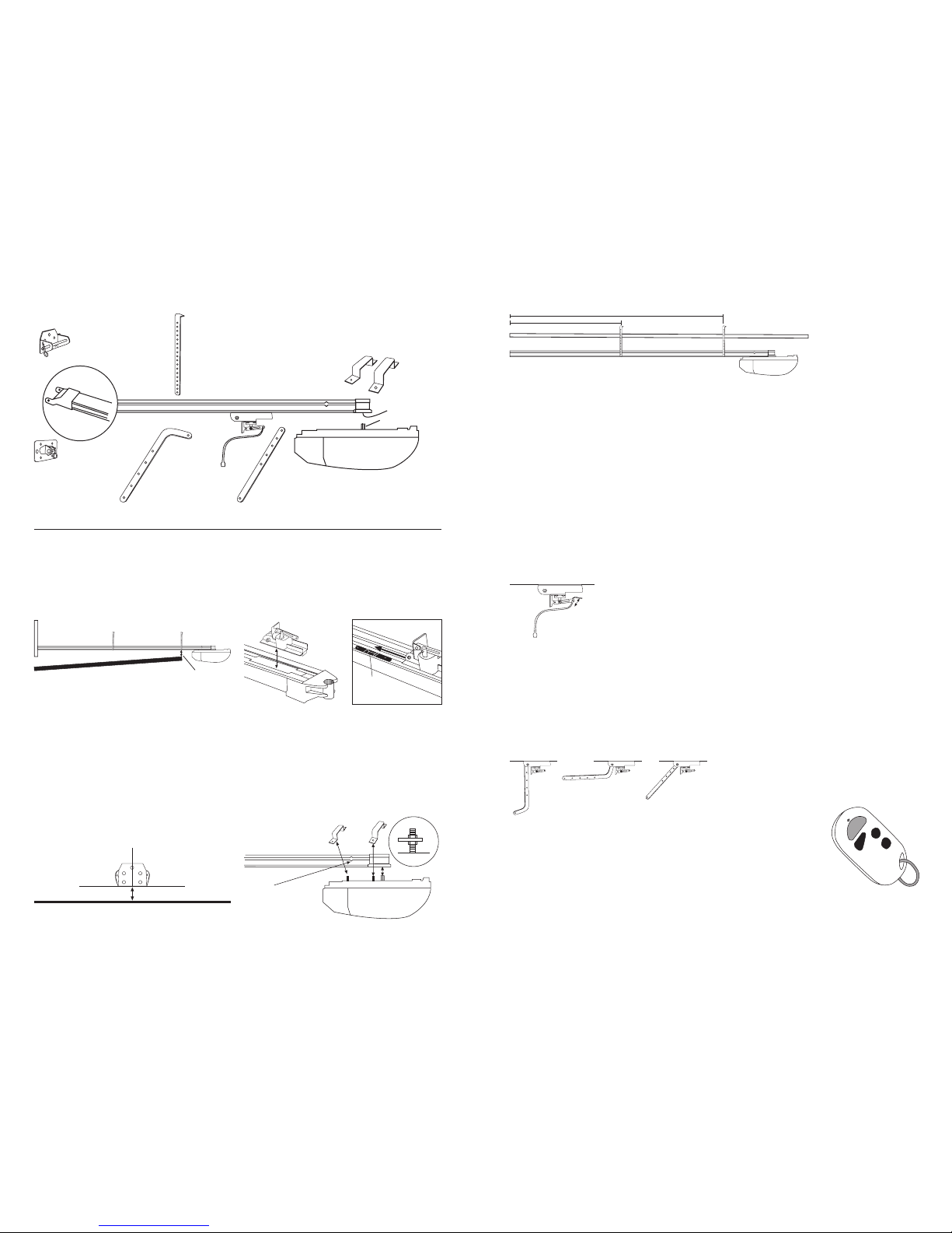
Front Assembly Bracket (Step 1)
MCU Brackets & Nuts (Step 2)
Arm Transport (Step 2)
Mounting Bracket Slider Bolts (Step 3)
Manual Bypass Cord (Step 4)
Garage Door Bracket (Step 4)
Garage Door Bolts (Step 4)
Remote Control x 3 (Step 6)
Thank you for purchasing the ORCA GarageAce. The unit is easy to install
and provided these instructions are followed, will provide many years of
smooth, trouble-free operation.
The photos at left are provided to help you identify the fastenings supplied.
In addition you will need appropriate screws to attach both the Front Assembly
Bracket and Mounting Brackets to the garage framework.
Warning: This opener is not to be used as a solution for hard-to-open doors.
The garage door must be properly balanced and easy to open manually before
installing the ORCA GarageAce Garage Door Opener.
Important Information
Do not allow children to play with door controls.
Keep remote controls away from children.
Watch the moving door and keep people away until the door is completely
opened or closed.
When using an electrical appliance, basic precautions should be observed to
reduce the risk of fire, electric shock, or injury:
1. Before connecting the unit to the power supply, make sure the voltage
indicated on the appliance corresponds with the voltage in your garage.
Otherwise, contact your dealer and DO NOT use the unit.
2. Use only as described in this manual. Use only manufacturer’s
recommended accessories.
3. Do not use extension cords or outlets with inadequate current carrying
capacity. Care should be taken to arrange the power cord so that it cannot
be pulled or entangled.
4. Never disconnect by pulling the cord; grasp plug and pull to disconnect.
5. Close attention is necessary when installing or operating near children
or pets.
6. Do not handle plug with wet hands.
7. To protect against fire, electric shock or personal injury, do not expose
cord or electric plugs to water vapours or other liquids.
8. Do not use the appliance if it appears damaged. All repairs, including
replacement of the power cable, must only be carried out by the authorized
service centre.
9. Use caution when operating the manual release with the door open since
the door may fall rapidly due to wear or broken springs or a door not
properly balanced.
10. Frequently examine the installation, in particular cables, springs and
mountings for signs of wear, damage or poor balance. Do not use if repair
or adjustment is needed since a fault in the installation or an incorrectly
balanced door can lead to injury.
Read all instructions carefully.
Garage Door Opener for Tilt Doors and
Sectional Doors only.
Maintenance
No particular maintenance is required for the Motor Control Unit. However,
check at least twice a year that the unit is in proper working order. Adjust
if necessary the motor force. Make sure that the safety devices are working
effectively. Check the tension on the chain. An adjustable bolt on the
Front Assembly will tighten/loosen this tension (Fig 8).
Check once a month that the drive reverses when an object (40mm or
higher) is placed in the door’s path. Adjust if necessaryand recheck since
an incorrect adjustment may present a hazard.
If you experience any problems, contact ORCA on Freephone 0800
ORCAHELP.
Technical Data
Model: GDO Tilt
Maximum door size: 5.5 metres wide; 2.4 metres high
Power input: 230-240V 50Hz
Motor: 24V DC 100W
Fuse: 3A 240V 5x20mm
Rated power input: 300W
Courtesy light time: 3 minutes
Working temperature: -20~+70C
Relative humidity: < 90%
Open and close force: 600N
Auto Reverse: returns to open position on meeting an obstruction
Built-In Receiver: Reception frequency: 433.22Mhz
Sensitivity: greater than 1V for correct receiver signal, (average range
50m with an aerial)
Decoding: rolling code
Transmitter power: 27A 12V Battery
Manual over-ride via service cord in event of power failure
ORCA has the right to modify it’s product at any time without prior notice.
Accessories:
The ORCA GarageAce has a number of optional accessories available
to enhance the functionality of your GarageAce. Consult your retailer
for details on . . .
Battery Back-up Part No. OGA-BBU
If the power goes off, the GarageAce can be operated manually
from the inside – but with a battery back-up you can still operate
the door from the comfort of your car!
Photo Safety Beam Part No. OGA-PSB
If you have young children around, the safety beam will protect
them when the door is closing. Perfect for peace of mind.
Outside Disconnect Mechanism Part No. OGA-ODS
A key-lock mechanism that operates the manual bypass from
outside the door. Great for garages where there is only one entrance.
Remote Control Transmitter Part No. OGA-RCU
Additional or replacement units are always available.
Cat. OGA-GDO
SafetyAce
Fire Extinguisher
Great for the home, garage, vehicle, caravan,
boat. A small sized extinguisher that packs a
powerful punch.
Designed for class A, B and E fires, the SafetyAce
is just what you need!
Cat. OSA-FE
Don’t forget these other great ORCA products . . .
IMPORTANT
SAFETY
INSTRUCTIONS
Warning:
It is vital for the
safety of persons
to follow all
instructions.
Incorrect
installation can
lead to severe
injury.
Save these
instructions.
Figure 8
Adjustable Tension Bolt
Step 4: Attach the Door.
(Figure 6) If it is not already in place,
attach the Manual Bypass Cord to the
nylon Arm Transport. This should be
at a reachable height of less than 1.8
metres. Pull this down to free up the
transport and slide it close to the door.
Choose the appropriate Garage Door Arm for your door type (Figure 7).
Bolt into place on the Arm Transport. Attach the Garage Door Bracket to
the other end. Position this bracket against the top edge of the garage
door (and directly below the Front Assembly Bracket) and bolt or rivet
bracket in place on the door (some bolts are supplied for this purpose).
Move the door so that the Garage Door Arm and Arm Transport assembly
slide along until the Arm Transport once more locks into the Arm Transport
Locator.
Make sure the lbel concerning the manual release is attached to the
actuating member.
Motor Control Unit (MCU)
Front Assembly
Front Assembly Bracket
Chain Drive
Mounting Brackets (4)
MCU Brackets
Gear Socket
Arm Transport
Garage Door Bracket
Garage Door Arm (Tilt)
Garage Door Arm (Sectional)
Manual Bypass Cord
Component Identification
Installing the Orca GarageAce
Preliminary:
The ORCA GarageAce is positioned along the garage rafters
central to and above the path taken by the garage door when it opens
and closes (Figure 1). There should be a minimum gap of 30mm between
the bottom of the Chain Drive and the top of the Garage Door at its closest
point. The Mounting Brackets allow for considerable height adjustment
but please make sure the correct positioning is possible before you
begin. Additional timber braces may need to be installed to attach the
Mounting Brackets.
If you are installing with an existing garage door, make sure all existing
locking devices are removed before beginning installation.
Close the door before you begin.
Step 1: Install the Chain Drive Front Assembly Bracket
(Figure 2) Measure the garage door width and mark the centre. Using a
spirit level, extend a vertical line above the top of the door on the inside
of the front wall. Measure approx. 65mm from the top of the door upwards.
Mark a horizontal line. Locate the Front Assembly Bracket. Position this
so that it is centred on your vertical line and the bottom (non-tapered)
edge of the bracket is sitting on your horizontal line. Screw into place
(screws not supplied). Important: Bracket must be attached to
solid timber or masonry.
Figure 1
Garage Door
30mm minimum gap
Figure 2
65mm
Top of Garage Door
Front Assembly Bracket
Centre Line
Step 2: Attach the Arm Transport and Motor Control Unit
Slip the Arm Transport Unit into the gap at the rear end of the Chain Drive
(Figure 3a). Be sure it faces the correct way – the metal arm faces
backwards. Slide the Arm Transport along until it clicks into the brass
Arm Transport Locator and locks in place (Figure 3b). Push on the Arm
Transport so that the whole chain moves and slide along until the Arm
Transport is approximately half way along the Chain Drive.
Using the slider bolts supplied slide two bolts into the Bolt Entry gaps
on each side of the Chain Drive.
(Figure 4) Attach the Motor Control Unit (MCU) to the end of the Chain
Drive, ensuring that the Drive Gear sits properly in the Gear Socket at the
end of the Chain Drive. There are two MCU Brackets, one narrower than
the other. Fit the wider one over the bolts closest to the Drive Gear and
the narrower one over the other set of bolts. It is important that you
fit a spacer nut on each of these bolts before mounting the
brackets to reduce excess tension on the MCU. Using the nuts
provided, secure the brackets in place.
Figure 3a
Arm Transport
Gear
Socket
Figure 3b
Brass Arm
Transport Locator
Arm Transport
Motor Control Unit (MCU)
MCU Brackets
Drive Gear
Bracket
Nut
Bolt
(Narrower)
(Wider)
Figure 4
Nut
Step 3: Mount the Assembly
Carefully position the Chain Drive and MCU assembly on the floor, with
the MCU furthest away from the door. Lift up the other end (with the
nylon bracket) and secure to the Front Assembly Bracket, sliding the bolt
through both sets of holes and securing the cotter pin on the outside.
(Figure 5) there are four Mounting Brackets for securing to the rafters,
with one pair (“inner”) approx. 1400mm from the front wall and the
second pair (“outer”) approx. 2800mm from the front wall. Mark these
distances on the rafters for easier positioning later.
Using the slider bolts, secure first set of these to the inner Mounting
Brackets, the second set to the outer Mounting Brackets, using the nuts
provided.
Lift up the assembly and position the outer Mounting Brackets over the
marks made previously and screw into place, making sure the Chain
Drive is level. Secure the inner Mounting Brackets in place, once
again using your marks as a guide.
Excess overhang on the Mounting brackets can be either cut off or the
brackets bent upwards to remove any hazardous overhang.
Motor Control Unit
Mounting Bracket ‘Inner’
Mounting Bracket ‘Outer’
1400mm
2800mm
Figure 5
Figure 6
Arm Transport
Manual Bypass Cord
Figure 7
Preferred
for
sectional
doors
Acceptable
for tilt doors
Preferred
for tilt doors
Step 5: Connecting the Electrics
In the top of the MCU are a double set of wires, a single wire and an
outlet cord. The double set is for attaching an optional battery back-up
(not supplied). This can be tucked out of the way. The single wire is an
antenna for remote control operation. Leave this hanging free.
Plug the outlet cord into a convenient outlet. Ideally this will be one
installed at ceiling level but an extension cord may be used to reach to
an existing outlet. All cords must be tied up neatly to avoid any chance
of snagging, pulling or entangling.
Step 6: Program the Unit
Make sure the unit is plugged in. Locate the four buttons on the base of
the Motor Control Unit – labelled UP, DOWN, SET, CODE. These will be
used to program the unit.
Setting the open and close positions:
1. Press and hold UP until the LED displays the letter L.
2. Press UP button and hold, the door will travel to the opening position,
release the button when the door has reached the desired position.
3. If the door has over-run its position, press DOWN button to move
the door downwards. Adjust the position by pressing UP and DOWN
button.
4. Press and hold SET button to confirm open position. The LED will
now display the letter d. It is now time to set the closed position.
5. Press and hold the DOWN button, the door will travel to the closing
position, release the button when the door has reached the closed
position.
6. If the door has over-run its position, press the UP button to move
the door upwards. Adjust the position by pressing DOWN and UP
button.
7. Press the SET button to confirm. The door will now open and
close as the force requirements are set.
8. The door is now set for normal operational mode.
Setting Force Adjustment:
Normally the force settings are automatically set at 3 and adjustment is
not necessary, however the force can be adjusted for a special purpose.
The adjustment range is between 1 (min) & 9 (max).
A photoelectric
safety beam must be fitted if setting the force above 3.
9. Press DOWN button and hold, the LED will display a setting number
from 1 to 9, release the button, it is now in force adjustment state.
10. Press DOWN to increase the force one degree, and press UP to
decrease one degree.
11. Press SET to confirm.
Chain Drive
(Upside
down)
Drive Gear
Programming the Remote Control (Transmitter):
The supplied Remote Control units can be programmed for any number
of purposes. Although the unit has four buttons, only one is needed to
operate the GarageAce. The same button will open and close the door.
If you have other devices (such as a burglar
alarm) that can program a remote control,
use the other buttons for this purpose.
A. Press receiver program button,
CODE and release until the LED
displays a dot. Press the preferred
button of Remote Control (Transmitter)
then release and press again. The dot will
flash to confirm the code.
B. Repeat step A for each Remote Control.
To delete all stored codes, press and hold CODE for 8 seconds until the
dot turns off. All stored codes have now been deleted.
Bolt Entry
Gap for
Slider Bolts
 Loading...