

ORBRY Smart Touch, Smart Touch Thermostat User Manual
Smart Touch
Thermostat
Colour
Touchscreen
Thermostat
OBSMART

DO DO NOT
Install a conduit for your
sensor probe before thermostat installation.
Ignore electrical regulations.
Install this thermostat in
a wet zone.
The Orbry Smart Touch Thermostat is IP30 rated and suitable for
safe installation in bathrooms. It is not suitable for use in special locations, such as wet zones. All electrical circuits in bathrooms must
be protected by a 30mA RCD. The instructions we supply include as
much information as possible to ensure that all installations comply
with current electrical regulations. Please call our customer support
line, if in any doubt, on 0845 208 0221.
The Orbry Smart Touch Thermostat is a digital thermostat, which is
designed for electric underoor heating systems with a maximum
load of up to 16A (3600W). The Orbry Smart Touch features a 4.3”
colour touchscreen display and four (4) languages.
ALL WIRING MUST CONFORM TO
IEE 17TH EDITION PART P REGULATIONS.
THIS PRODUCT IS RATED IP30.
Orbry Smart Touch Thermostat
INTRODUCTION
IMPORTANT SAFETY REGULATIONS
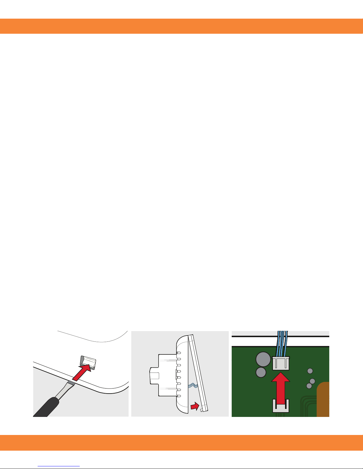
Place the unit face down on a hard surface and push the three (3)
clips located on the bottom of the Orbry Smart Touch in with
a screwdriver to release the face plate.
Once the face plate has been gently opened disconnect the ribbon
cable to release the face plate.
Step 1: Release the face plate
Step 2: Disconnect ribbon cable & remove face plate
The sensor conduit and deep back box must be tted before
installation of the actual thermostat can begin. Feed the sensor
probe provided down through the sensor conduit into
a representive area of the oor. For technical advice or help with
any queries, please call our customer support team
on 0845 208 0221 or visit www.orbry.com/orbry-downloads.
Before you begin
Installation
INSTALLING THE ORBRY SMART TOUCH
1. 4.
2. 5.
3.
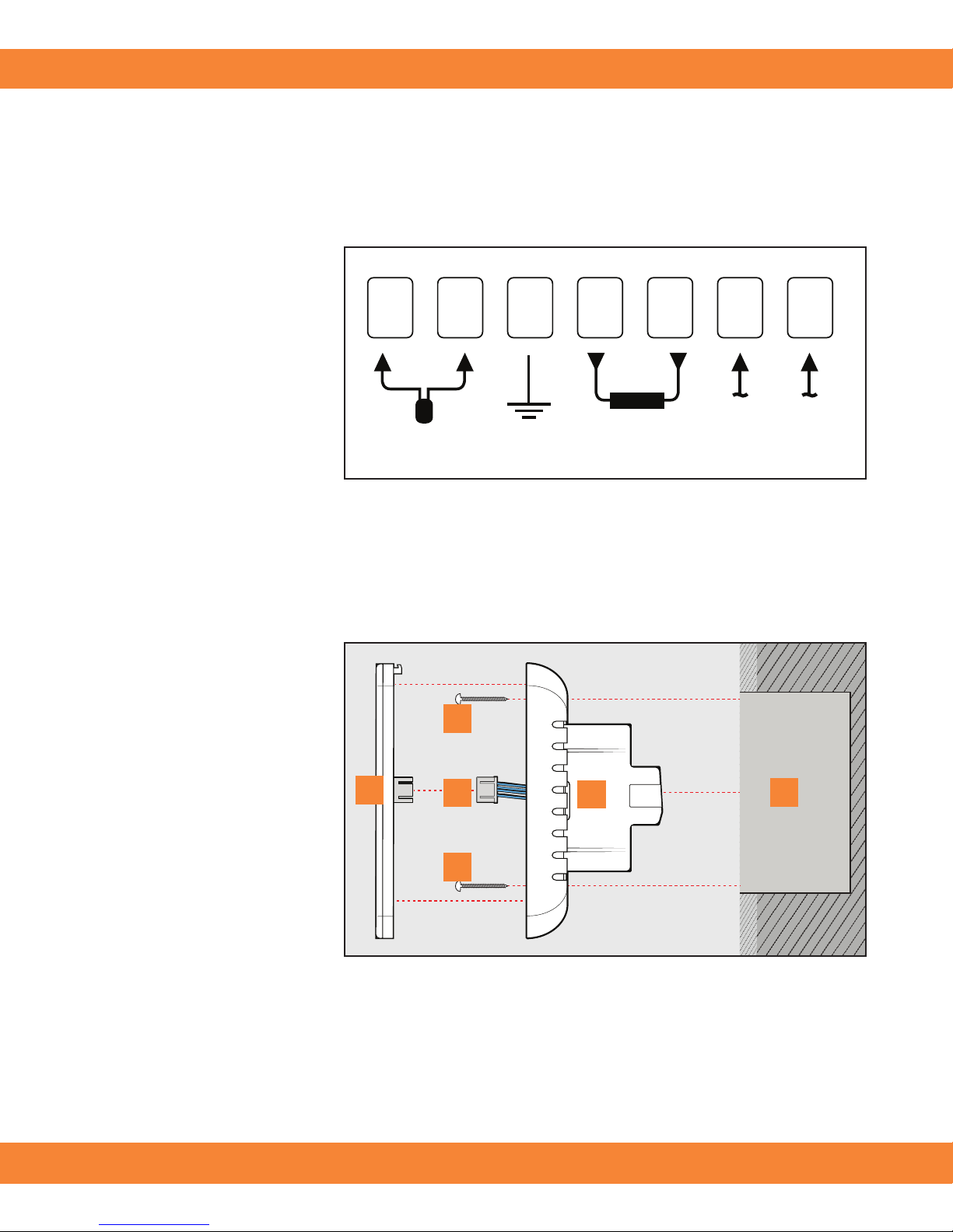
Fix the Orbry Smart Touch Thermostat to the wall
Align the Orbry
Smart Touch with
your back box and
x in place with the
screws provided.
Now, reconnect the
ribbon connections
and reseat the face
plate (bottom edge
rst). Ensure the
Orbry Smart Touch
is securely xed
before continuing.
Faceplate
Provided screws
Ribbon connectors
Back plate
Back box
Wire and replace the face plate
Sensor
7 6 4 3 2 15
LL
3600W/16A
230V/AC
NN
Loosen the tension
screws to allow the
wires to be inserted
and xed. Position
the cables as shown
in the wiring diagram
and ensure each
screw is tightened
correctly.
Ensure system is correctly earthed.
WIRING THE ORBRY SMART TOUCH
1
5
4
3
2
2
 Loading...