

Page 1

V052015
OPERATING MANUAL (ENG
)
Page 2
WARRANTY
All Orbot equipment has been carefully tested and inspected at our USA factory. Orbot machines are
guaranteed for one year from the date of original purchase against defects or workmanship made during
manufacture. Within the guarantee period we undertake at our discretion, to repair or replace any part
found to be defective, free of charge to the purchaser with subject to the following conditions:
Claims made under the terms of the guarantee must be supported by the original invoice issued at the
time of sale along with the machine serial number.
For claims under this guarantee contact the supplier from whom you’ve purchased the product who will
arrange the appropriate action. Do not initially return the product as this could lead to transit damage.
Neither Orbot nor its distributors will be held responsible for any incidental or consequential loss.
This guarantee does not cover:
Periodic maintenance, repair, or replacement of parts due to normal wear and tear.
Damage caused by accident, misuse or neglect, re, or the tting of other than genuine Orbot parts.
Defects in other than genuine Orbot parts, repairs, modi cations or adjustments made by other than
a Orbot service engineer or authorized service dealer. Costs and risks of transport relating directly or
indirectly to the guarantee of this product. Consumable items such as brushes, drivers, velcro discs,
gliders, pads, and so forth. Orbot has a policy of continual product development and we reserve the right
to alter speci cations without prior notice.
Model:
Serial:
Date of Purchase:
Dealer:
Address:
Phone Number:
Sales Representative:
Machine Type: Floor Model: Orbot Sprayborg
This Machine is in conformity with the following EU directives:
- Machinery Directive: 2006/42/EC
- Electro Magnetic Compatibility Directive: 2004/108/EC
- In conformity with 2006/95/EC
Applied harmonized standards:
EN 60335-1, EN 60335-2-67
MACHINE DATA
EC Declaration of Conformity
HOS GmbH
Hruby Orbital Systems
Kleiststraße 7
10787 Berlin
Date: 02/08/2010
2
Jeffrey Hruby CEO
Page 3

TABLE OF CONTENTS
Warranty
EC Declaration of Conformity
How to use this Manual
Safety
Technical Details
Operation
Unpacking and Initial Operations
Pre-Run Inspection
Power Cable Connection
Spray System Preparation
Spray Jets
Adjusting Height
Process of Cleaning
End of Application
2
4
5 - 7
8
9 - 16
9
10
11
Storage
Lifting and Carrying
Weight Kit Installation
Brush Installation
Attaching and Removing the Driver Plates
Accessories and Applications
Driver Plates
Standard Driver Plates
Carpet Pads
Melamine Pads
AkwaStrip Pads
StoneFlash Pads
Scrub Brush
Concrete Brush
Operation/Maintenance
12
13
14
15
16
17
Application on Different Floor Types
Cleaning the Machine
Changing the driver grip face
Parts Diagram and Parts List
Notes
18 - 38
39
3
Page 4

HOW TO USE THIS MANUAL
This manual contains the following sections:
• How to Use This Manual
• Safety
• Operations
• Maintenance
• Parts List
The HOW TO USE THIS MANUAL section will tell
you how to nd important information for ordering
correct repair parts.
Parts may be ordered from authorized dealers.
When placing an order for parts, the machine
model and machine serial number are important.
Refer to the MACHINE DATA box which is lled
out during the installation of your machine. The
MACHINE DATA box is located on the inside of the
front cover of this manual.
The model and serial number of your machine
is located on the left side of the handle, from the
operators perspective.
The PARTS LIST section contains assembled parts
illustrations and corresponding parts list. The parts
lists include a number of columns of information:
• REF – column refers to the reference number on
the parts illustration.
• PART NO. – column lists the part number for the
part.
• PRV NO. – reference number.
• QTY – column lists the quantity of the part used in
that area of the machine.
• DESCRIPTION – column is a brief description of
the part.
• SERIAL NO. FROM – If this column has an (*) and
a Reference number, see the SERIAL NUMBERS
page in the back of your manual. If column has
two asterisk (**), call manufacturer for serial
number. The serial number indicates the rst
machine the part number is applicable to. The
main illustration shows the most current design of
the machine. When a boxed illustration is shown,
it displays the older design.
• NOTES – column for information not noted by the
other columns.
The SAFETY section contains important information
regarding hazardous or unsafe practices of the
machine. Levels of hazards are identied that could
result in product damage, personal injury, or severe
injury resulting in death.
The OPERATIONS section is to familiarize the
operator with the operation and function of the
machine.
The MAINTENANCE section contains preventive
maintenance to keep the machine and its
components in good working condition. They are
listed in this general order:
• Storage
• Maintenance
• Troubleshooting
NOTE: If a service or option kit is installed on your
machine, be sure to keep the KIT INSTRUCTIONS
which came with the kit. It contains replacement
parts numbers needed for ordering future parts.
NOTE: The manual part number is located on the
lower left corner of the front cover.
4
Page 5

WARNING
SAFETY
IMPORTANT SAFETY INSTRUCTIONS
When using this machine, basic precaution must always be followed, including the following:
READ ALL INSTRUCTIONS BEFORE USING THIS MACHINE.
To reduce the risk of re, electric shock, or injury:
• Use only indoors. Do not use outdoors or expose to rain.
• Use only as described in this manual. Use only manufacturers recommended components and
attachments.
• If the machine is not working properly, has been dropped, damaged, left outdoors, or dropped into
water, return it to an authorized service center.
• Do not operate the machine with any openings blocked. Keep openings free of debris that may reduce
airow.
• Machine can cause a re when operating near ammable vapors or materials. Do not operate this
machine near ammable uids, dust or vapors.
• This machine is suitable for commercial use such as: in hotels, schools, hospitals, factories, shops, and
ofces for more than normal housekeeping purposes.
• Maintenance and repairs must be done by qualied personnel.
• During operation, use caution around other persons, especially children.
• The machine shall only be operated by instructed and authorized persons.
• When leaving unattended, unplug the machine.
• Do not handle the plug or machine with wet hands.
• Do not unplug machine by pulling on cord. To unplug, grasp the plug and not the cord.
• Do not use with damaged cord or plug. Follow all instructions in this manual concerning grounding the
machine.
• Do not pull or carry by cord, use cord as a handle, close a door on cord, or pull cord around sharp
edges or corners.
• Do not pull/run machine over cord. Keep cord away from heated surfaces.
• Connect to a properly grounded outlet. See Grounding Instructions.
• If the supply cord is damaged it must be replaced by an authorized service agent.
• Unplug before cleaning or servicing.
• Operational hazard may occur when running the machine over the supply cord.
• This appliance has been designed for use with pads specied by the manufacturer. The tting of other
pads may affect its safety.
• This machine is for dry use only and shall not be used or stored outdoors in wet conditions
• Moving Parts - To reduce the risk of injury, unplug before servicing.
READ AND SAVE THESE INSTRUCTIONS
5
Page 6

WARNING
CAUTION
SAFETY
The following symbols are used throughout this guide as indicated in their descriptions:
HAZARD INTENSITY LEVEL
There are three levels of hazard intensity identied by signal words -WARNING, CAUTION, and FOR
SAFETY. The level of hazard intensity is determined by the following denitions:
WARNING - Hazards or unsafe practices CAN result in severe personal injury or death.
CAUTION - Hazards or unsafe practices which could result in minor personal injury or product or
property damage.
FOR SAFETY: To Identify actions which must be followed for safe operation of equipment.
Report machine damage or faulty operation immediately. Do not use the machine if it is not in proper
operating condition. The following is information that signals some potentially dangerous conditions to
the operator or the equipment. Read this information carefully. Know when these conditions can exist.
Locate all safety devices on the machine. Please take the necessary steps to train the machine operating
personnel.
FOR SAFETY:
DO NOT OPERATE MACHINE:
• Unless trained and authorized.
• Unless Operation Guide is read and understood.
• In ammable or explosive areas.
• In areas with possible falling objects.
WHEN SERVICING MACHINE:
Avoid moving parts. Do not wear loose clothing, jackets, shirts, or sleeves when working on the machine.
Use only manufacturer approved replacement parts.
6
Page 7
GROUNDING INSTRUCTIONS 120V
WARNING
THIS PRODUCT IS FOR COMMERCIAL USE ONLY
ELECTRICAL:
In the USA this machine operates on a 15 amp
nominal 120V, 60 hz, A.C. power circuit. The
amp, hertz, and voltage are listed on the data label
found on each machine. Using voltages above or
below those indicated on the data label will cause
serious damage to the motors.
GROUNDING INSTRUCTIONS:
This appliance must be grounded. If it should
malfunction or break down, grounding provides a
path of least resistance for electric current to reduce
the risk of electric shock. This appliance is equipped
with a cord that has an equipment-grounding
conductor and grounding plug. The plug must be
inserted into an appropriate outlet that is properly
installed and grounded in accordance with all local
codes and ordinances.
This appliance is for use on a nominal 120-volt
circuit, and has a grounded plug that looks like
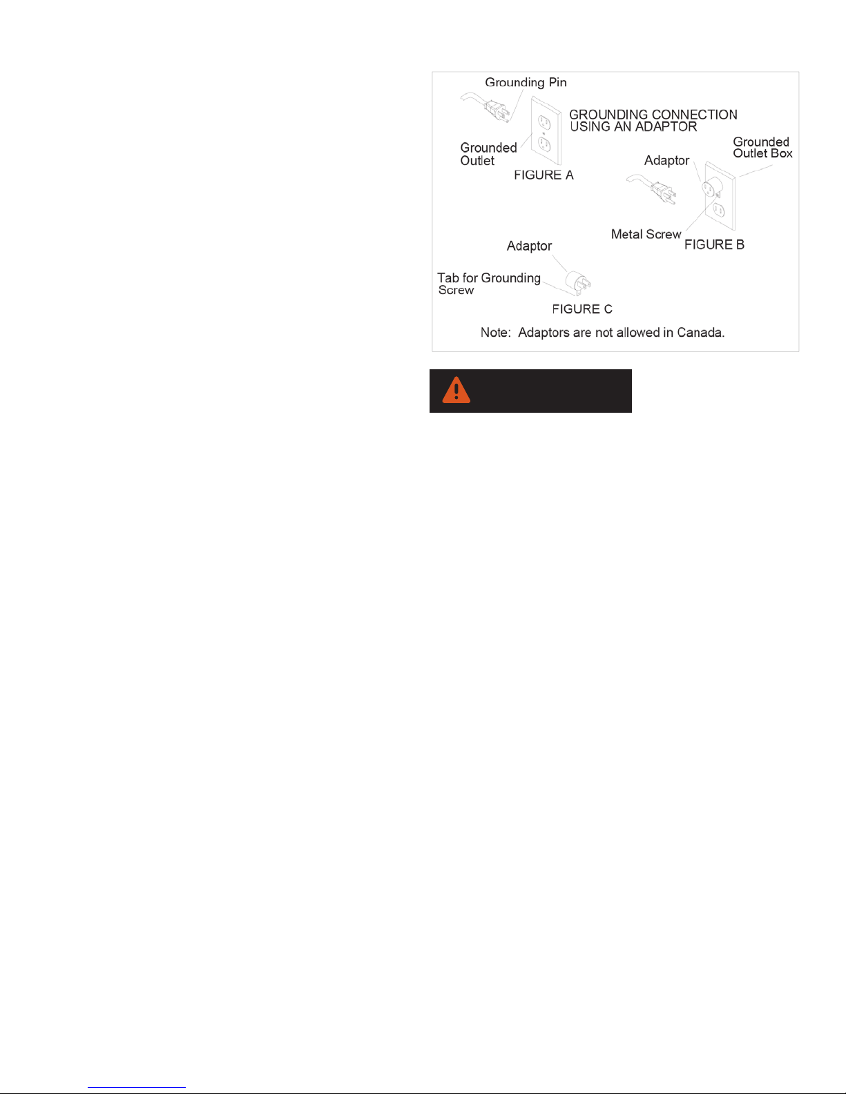
the plug in “Fig. A”. A temporary adaptor that
looks like the adaptor in “Fig . C” may be used to
connect this plug to a 2-pole receptacle as shown
in “Fig. B”, if a properly grounded outlet is not
available. The temporary adaptor should be used
only until a properly grounded outlet (Fig. A) can
be installed by a quali ed electrician. The green
colored rigid ear, lug, or similar that extends from
the adaptor must be connected to a permanent
ground such as a properly grounded outlet box
cover. Whenever the adaptor is used, it must be
held in place by a metal screw.
SAFETY
Improper connection of the equipment-grounding
conductor can result in electric shock. Check with a
quali ed electrician or service person if you are in
doubt as to whether the outlet is properly grounded.
Do not modify the plug provided with the appliance
- if it will not t the outlet, have a proper outlet
installed by a quali ed electrician.
SAFETY LABEL LOCATION
These drawings indicate the location of safety labels
on the Machine. If at any time the labels become
illegible, contact your authorized representative for
prompt replacement.
7
Page 8
TECHNICAL DETAILS
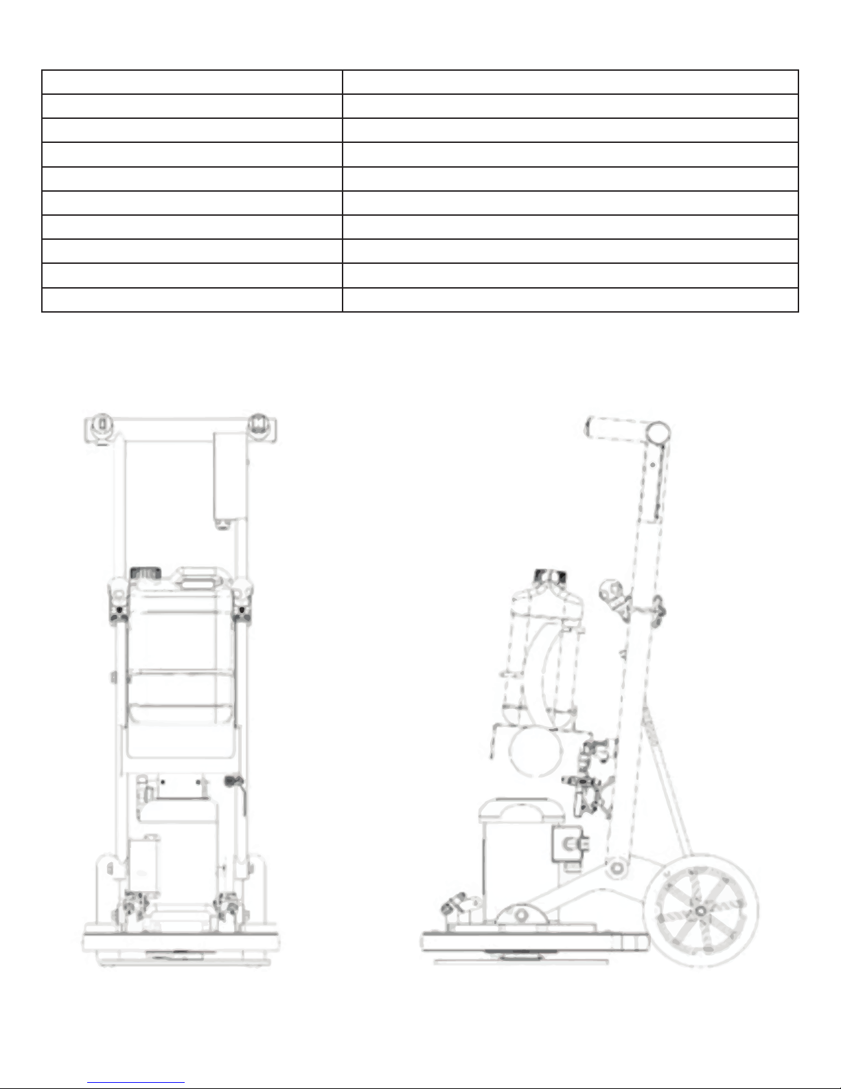
ITEM MEASURE
Motor 1HP, 100-240V/50-60Hz, 6 amps (50Hz)/11amp (60Hz)
RPM 1725 (60Hz)/1400 (50Hz)
Base Diameter 17“/43 cm
Orbital Diameter 3/8” (9.5 mm)
Weight 102 Lbs./46.7 kg
Height 48” (122 cm)
Length 29” (75 cm)
Wheels 10”/25 cm Diameter, resistant to chemicals
Decibel Rating 59 dB
8
Page 9
Unpacking and Initial Operations
CAUTION
WARNING
Open the shipping box on both sides, remove the
packaging material and roll the machine out of the box.
Pre-Run Inspection
Before each use, inspect the accessory such as the pad
driver for cracks, tears, or excess wear. If the machine or
accessory is dropped, inspect for damage to install an
undamaged accessory.
Repair the damaged machine before the next application.
Tilt the head back and place the foot of the bumper on the
ground.
Choose a pad for the appropriate application. Center the
pad on the driver plate.
Position the handle in a lower position.and push slowly
forward until the machine base tilts towards the ground.
OPERATION
Make sure to put the wheels back on the ground in time to
avoid the base from falling on the ground. This might cause
damage!
Check to make sure the power switch is in the “off” position.
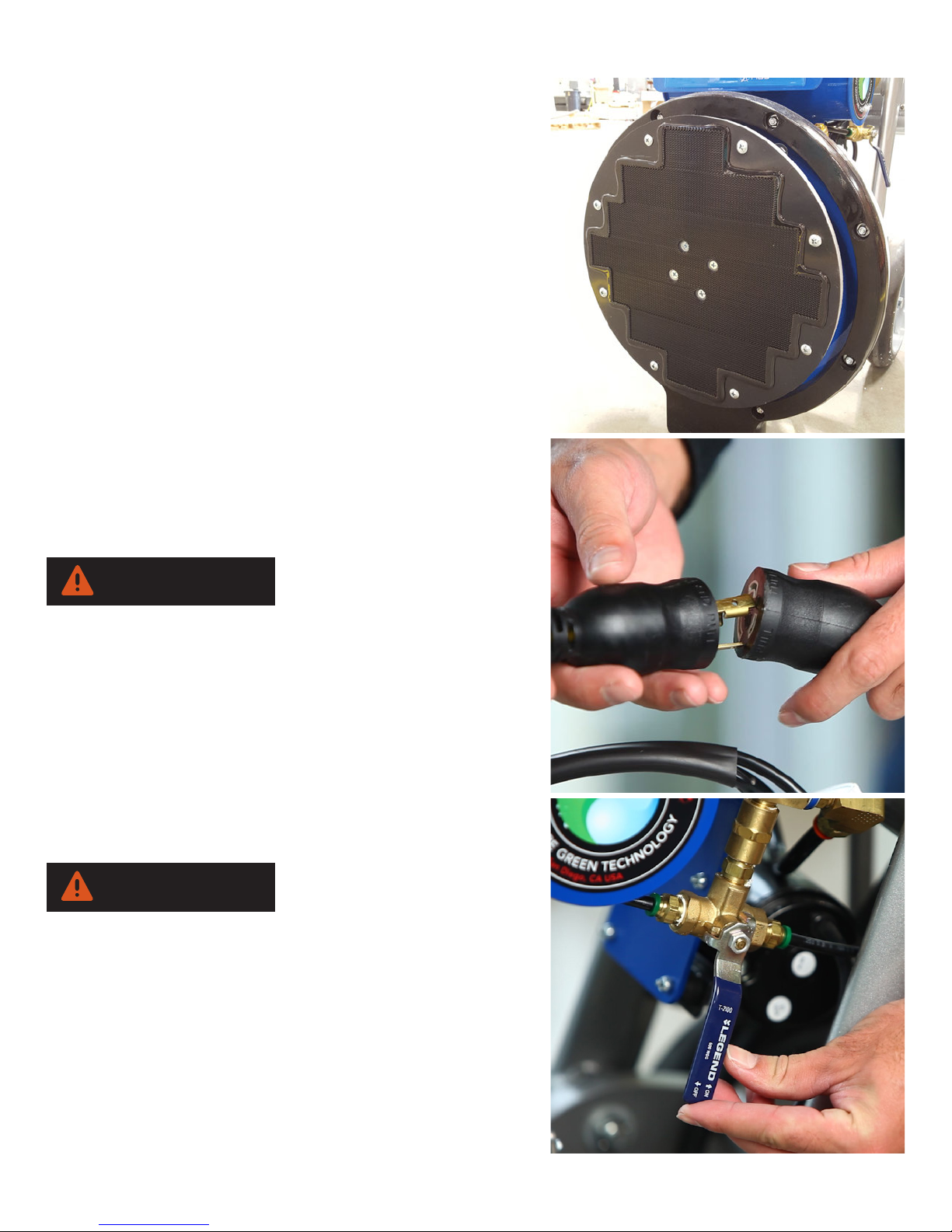
Power Cable / Quick Disconnect
Take provided power cable and connect to machine quick
disconnect located on machine. Push and twist to lock
cables together. You can now plug power cord into outlet.
Spray System Preparation
Fill the bottle cartridge with recommended cleaning solution.
For priming the pump system for the rst system, move the
valve lever to the vertical position and depress spray switch
for 30 seconds. For standard priming, 10 seconds is usually
sufcient.
By adjusting the valve lever you can vary the spray
9
Page 10
OPERATION
CAUTION
pressure. The further you move the lever counterclockwise
upwards, the higher the water pressure. A horizontal
position means maximum water output at maximum
pressure.
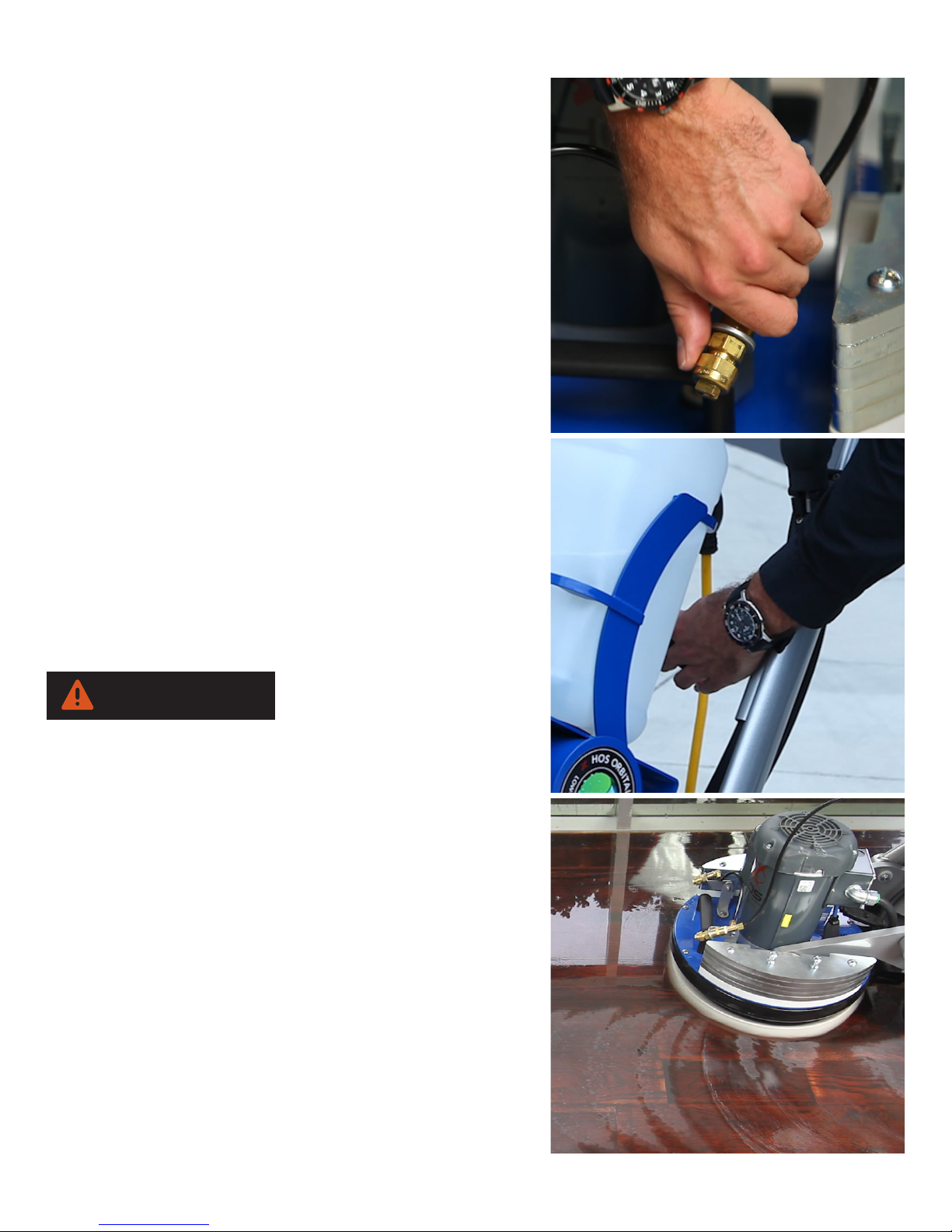
To turn the machine on, press the power button on the end
of the left handle.
Spray Jets
Adjust the spray jets on the machine base to the desired
position. For most oor cleaning applications adjust the
spray jets so that they spray about 6 inches (15 cm) in front
of the base.
Adjusting Height
Set the handle position to the desired height by pulling and
releasing the black knob with the left hand.
While holding the black knob out, raise or lower the handle
frame with your right hand.
To x the handle frame into place, release the black knob so
that it locks rmly into one of the holes provided.
Position “0” is off and position “I” is on.
Make sure a suitable pad or brush is mounted before
starting the machine. The immediate contact of the oor and
driver plate without a pad can lead to serious damage of
the oor and/or the machine.
Process of Cleaning
For effective oor cleaning, move the machine forward and
backwards. It is recommended to wet the oor as you move
the machine forward, releasing the solution button when
you move the machine backwards.
To increase the pressure and cleaning effect on certain oor
types like tile and grout, you can lift the machine frame up,
raising the wheels off the ground. When lifting the wheels
off the ground the full weight of the machine lies on the
machine base.
10
Page 11
CAUTION
Make sure the surface to be cleaned is not damaged by the
CAUTION
increase in pressure.
Omit this measure on very sensitive oors.
End of the Application
Turn off the machine by putting the on/off switch to “O”. If
a cleaning solution was used, ll bottle cartridge with water
and spray out system for 30 seconds.
Make sure to not let solution come in contact with the motor.
Storage
To avoid damage to the handle frame, DO NOT lay the
machine frame on the oor as done with other traditional
cleaning equipment. Remove the pad from the driver plate
by pulling it down rmly. Put the machine frame in an
upright position by pulling the black knob with the left hand
and move the handle frame upwards with the right hand.
OPERATION
The black knob should lock rmly in the top hole.
To allow an easy transportation of the machine, remove the
weight kit if used.
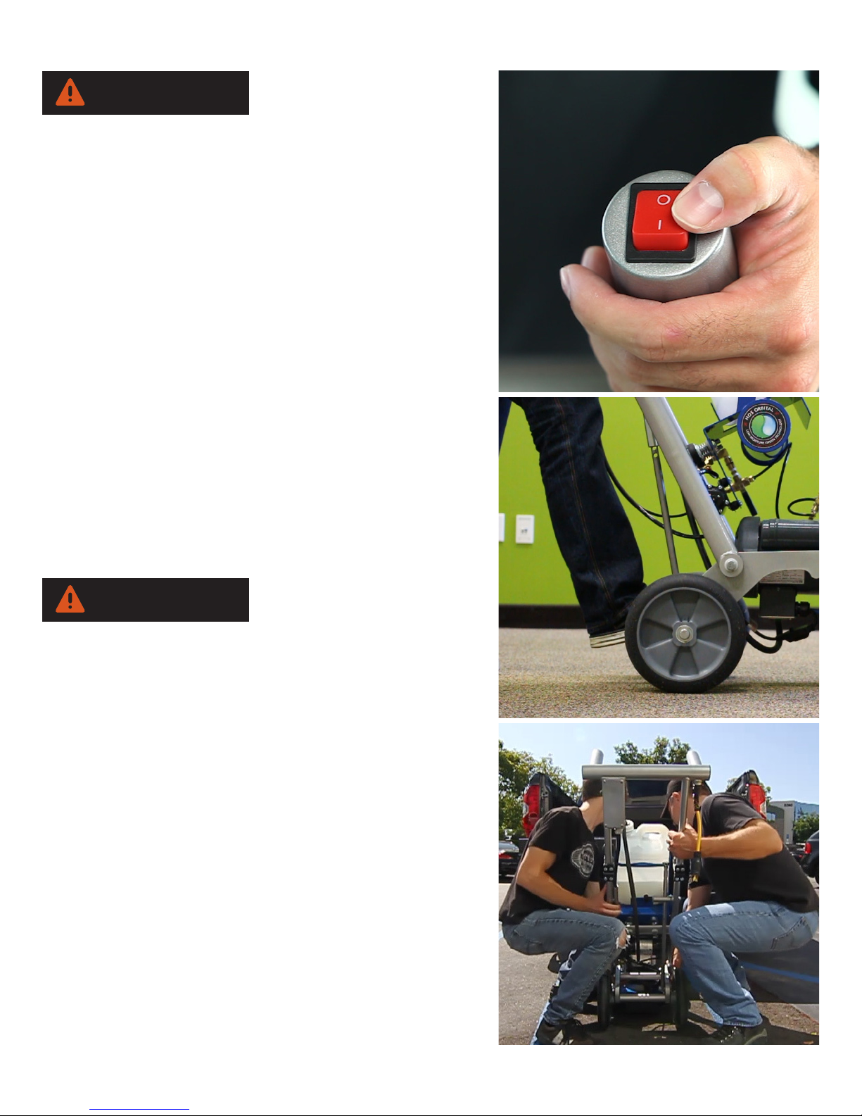
To easily roll the machine, push your foot on the back wheel
axle to create leverage and pull the handle towards your
body. The machine can be moved similar to a dolly now.
Always store with the base in the upright position.
Lifting and Carrying
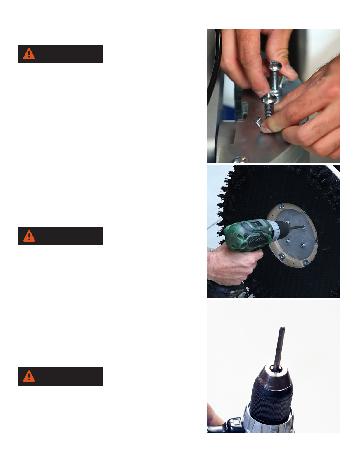
If you do not have a ramp, we recommend two people to
life machine in and out of a vehicle. Put the rmly locked
handle into a lowered position. Make sure that the machine
base rests on a pad, so that the grip surface of the driver
plate does not get damaged or hooked onto a carpeted
surface.
Grip the machine from each side as shown.
When lifting the machine in or out of the vehicle, set the
11
Page 12
OPERATION
WARNING
wheels down rst, followed by the machine base.
Make sure not to grip too close to the machine base. If the
base should ip upwards it can cause serious hand injuries.
Make sure you lift the machine with a back-friendly posture.
Secure machine rmly so it will not move.
Weight Kit Installation
The total weight of the weight kit is 40 lbs.
Put the weights on top of the mounting plates located on the
sides of the machine base.
Put the four screws into the holes provided on the weight
plates and fasten by turning clockwise.
Once the screws have threaded at least 5 full turns, tighten
the wing nuts by turning them clockwise, until the weights t
securely to the base.
CAUTION
Make sure that the weights are securely attached to the
base. Loose weights can cause serious damage.
For storage and transport we recommend removing the
weight kit. The machine can be transported more easily
without the weights.
Brush Installation
Put the machine base in an upright position, sitting on the
foot of the bumper.
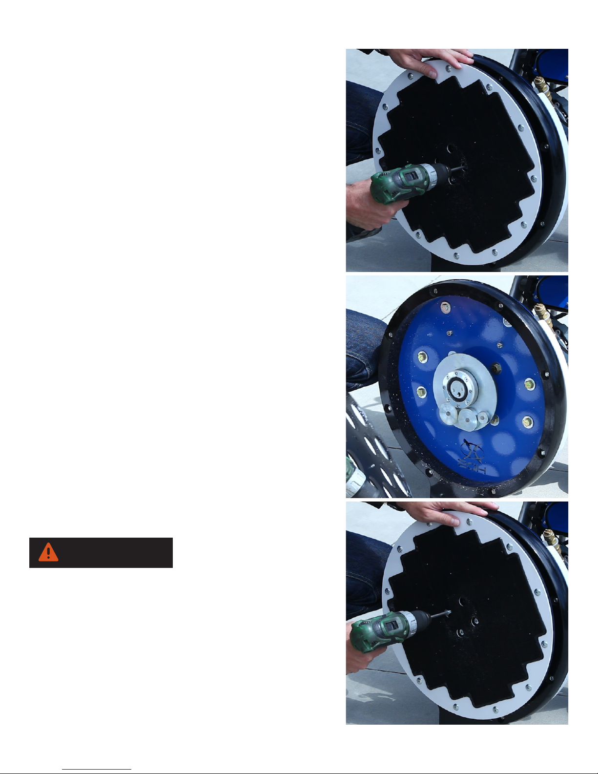
Remove the driver plate by removing the four countersink
screws in the center of the plate using an electric
screwdriver.
WARNING
It is important to only use a Number 3 Phillips head
screwdriver bit. Smaller bit sizes can damage the screw
heads and leave sharp edges, which can tear or snag the
pads. Damaged screws can cause further damage.
12
Page 13
Mount the brush with the same countersink screws used for
WARNING
mounting the driver plates.
• NOTE: Tighten the screws sufciently to avoid
disengagement of the brush from the machine during
operation.
To avoid stripping the screws do not over tighten. An electric
screwdriver with a clutch will ensure that stripping will not
occur.
Attaching and Removing the Driver Plates
Put the machine base in an upright position, sitting on the
foot of the bumper. Remove the driver plate by removing the
four countersink screws in the center of the plate using an
electric screwdriver.
Attach a driver plate to the machine base by lining up the
holes of the driver plate with the appropriate threads of the
bearing retainer ring. It is recommended to align the threads
of the bearing horizontally to the ground.
OPERATION
Put the four countersink screws through the holes of the
driver plate and rst screw them into the bearing retainer
ring threads manually. Then, tighten the screws with an
electric screwdriver
• NOTE: Tighten the screws sufciently to avoid
disengagement of the driver plate from the machine base
during operation.To avoid stripping the screws do not
over tighten. An electric screwdriver with a clutch will
ensure that stripping will not occur.
ACCESSORIES AND APPLICATIONS
Never store the accessories in wet conditions. Keep the
accessories away from extreme heat and from chemicals.
13
Page 14
OPERATION
WARNING
WARNING
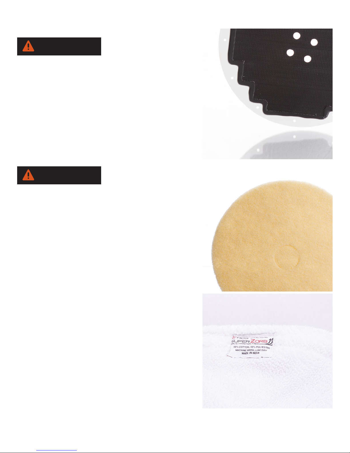
Driver Plates
Exclusively use designed driver plates only. The use of other
driver plates will damage the machine and its mechanical
action.
The driver plates are fastened on the machine base with
four countersink screws.
Standard Driver Plate
The standard driver plate (17” in diameter) supplied is
suitable for use with all pads for textile and hard oor
applications. The pads can be easily attached and removed
from the driver disc.
Never put the driver on carpet without a pad attached as
this might cause serious damage to the oor.
AgiClean Pads
The beige AgiClean pads are made of a special blend of
bers and latex that allows gentle cleaning of heavily soiled
short-pile carpets as well as scrubbing of hard oors. Attach
the AgiClean pads by centering them onto the driver plate.
An AgiClean pad, used on both sides, cleans an
approximate area of 1000 -2000 sq. ft (100 to 200m²),
depending on oor type and level of soil. Rinse the
AgiClean pads after each use with clean water.
SuperZorb Pads
Our exclusive SuperZorb Pads are made of a special cotton
and polyester blend. One of the primary components that
help to extract an essential amount of soil from the carpet
bers, they also play an important role to achieve fast dry
times.
A SuperZorb Pad, used on both sides, cleans an
approximate area of 3000 sq. ft (280m²), depending on
oor type and level of soil. SuperZorb Pads are machine
washable and can be reused hundreds of times. Allow to
air dry.
14
Page 15

Melamine Pad
The Melamine pad can be used on stone, concrete, VCT,
marble and other porous surfaces.
Each pad can clean an approximate area of 2000 sq.ft.
(190m²) depending on oor type and level of soil.
AkwaStrip Pad
The AkwaStrip Pad is a chemical free stripping pad made
of a unique material lled with diamonds. They can be used
for deep cleaning and to remove wax off of vinyl, VCT,
linoleum, wood, safety tiles, and more.
An AkwaStrip Pad, used on both sides, cleans an
approximate area of 1000-2000 sq. ft (100 to 200m²),
depending on oor type and the level of wax and soil.
Make sure to thoroughly rinse with clean water after each
use.
OPERATION
StoneFlash Pads
Our newly redesigned StoneFlash pads are part of a 6
step system for grinding, honing, and polishing Marble,
terrazzo, travertine, limestone, and more.
Each pad cleans an approximate area of 5000sq.ft.
(460m²) depending on oor type and level of soil.
• NOTE: StoneFlash pads require the use of the Orbot
Weight Kit (sold separately).
15
Page 16
OPERATION
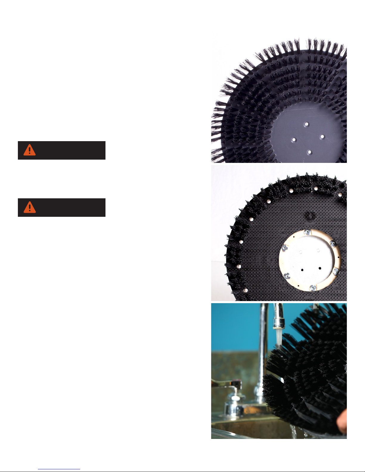
Scrub Brush
The bristles of the brush are made of high quality nylon.
The unique brush design is ideal for cleaning tile and grout,
smooth concrete, rubber ooring, and micro-porous surfaces
such as porcelain and safety tiles. It can also be used for
any other hard surfaces.
Concrete Brush
Our concrete brush is designed for outside concrete and
other rough surfaces. It is great for cleaning walkways with
minimal water.
WARNING
Never use the concrete brush on any other oor other than
specied outside concrete or rough surfaces, as this brush
will cause serious damage to all other ooring.
CAUTION
The use of the multi-purpose brush may splash in certain
applications. Take appropriate measures or use a splash
guard to prevent the wetting of walls and other obstacles.
Rinse the brush as needed with clean water after each
use. Depending on usage and care, you can use the multipurpose brush for many years.
• NOTE ON STORAGE: Never store the multi-purpose
brush with the bristles down. This can deform the bristles,
damage the brush, and reduce the cleaning performance.
You can bring deformed bristles back into their original form
by heating them with a heat gun.
16
Page 17
APPLICATION ON DIFFERENT FLOOR TYPES
WARNING
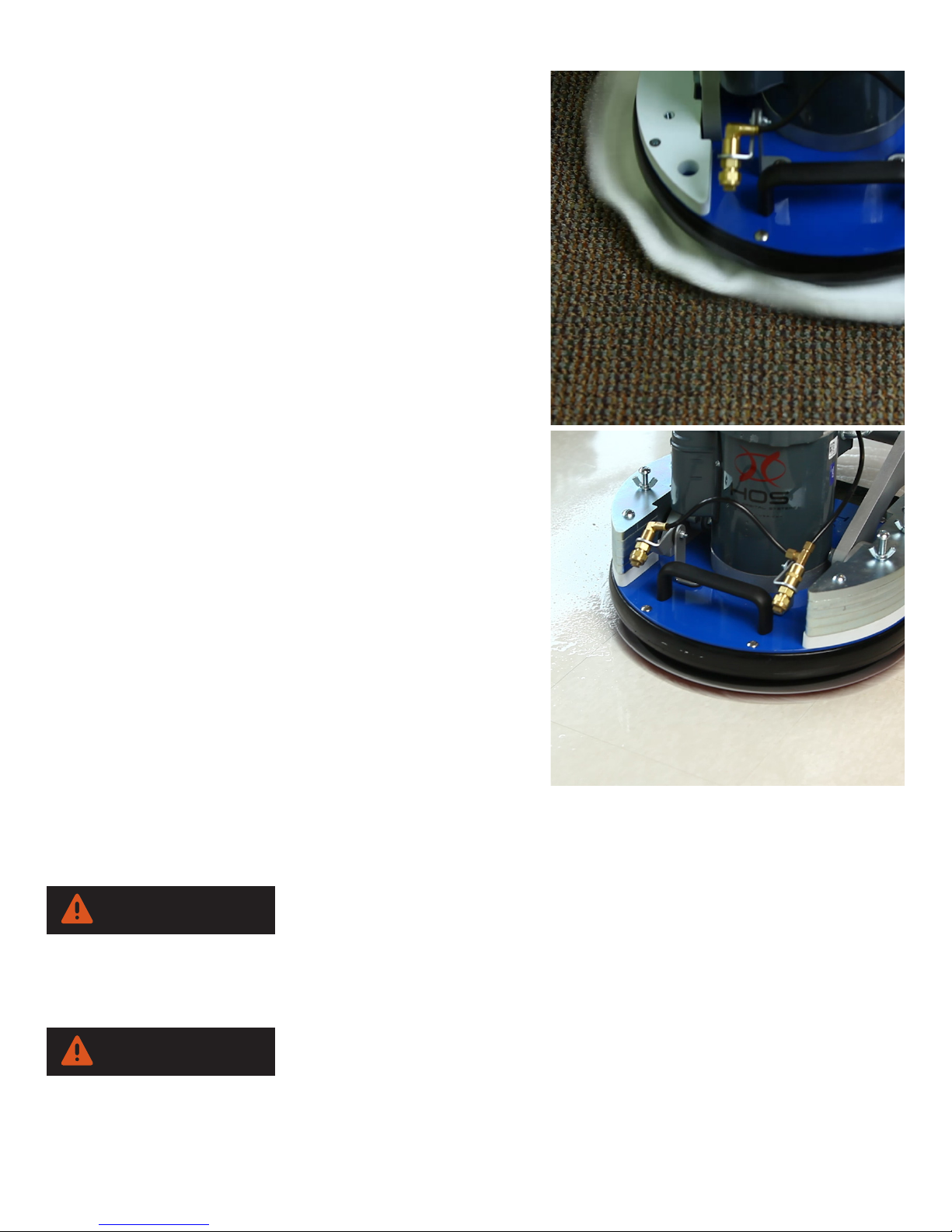
Carpet Cleaning
Vacuum the carpet thoroughly before cleaning. Large dirt
particles are removed, allowing the application to be more
effective.
Apply solution as you move forward. The carpet should
be cleaned by going forward and backwards two to three
times, while applying solution on the rst pass in order to
keep the drying time low. Depending on the level of soil
and the nature of the carpet, this process can be shortened
or extended. As required, carpets can be vacuumed again
after cleaning.
Cleaning Hard Floors
Remove dust and coarse dirt from the surface before
cleaning. Choose a suitable pad according to the
application. Place the pad in the center of the driver.
Gently lower the head on to the oor. Moving forward
and backwards while adding water cleans the surface.
w Use a cleaning solution as needed. Depending on soil
contamination and oor type, this process can be shortened
or extended.
OPERATION / MAINTENANCE
MAINTENANCE
Cleaning the Machine:
Clean the machine and bearing with a soft cloth and a
neutral pH cleaner. Regular cleaning of the bearing is
required to prevent build up that will cause it to seize up.
Changing the driver grip face:
Remove the ten outer screws that fasten the grip face disc
on the driver plate. To save time, use an electric screwdriver with a #3 Phillips Head bit.
WARNING
The Number #3 Phillips head bit is slightly larger than standard size. It is important that you are using a
#3 Phillips Head bit, as smaller bits can damage the screw heads and produce sharp edges which can
damage the cleaning pads. Attach a new grip face disc to the driver plate using the ten screws.
Make sure that the screws are very tight, not loose. If the screws are the slightest loose it can cause
damage to the grip face disc. Ensure that the four holes in the middle of the grip face disc are aligned
with the screws located on the driver plate. An exact alignment allows an easy removal and installation of
the driver plate.
17
Page 18

PARTS
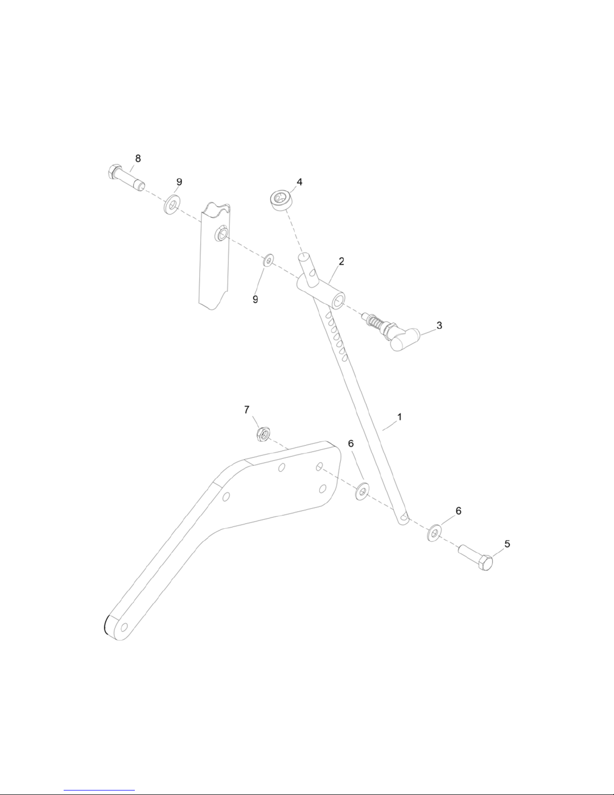
ITEM NO PART NUMBER QTY DESCRIPTION
1 1026 1 ROD, HANDLE
2 1022 1 LATCH BODY PULL
3 1025 1 LATCH, PULL
4 1027 1 COLLAR, HANDLE LATCH
5 1028 1 SCREW, 1/2-13 X 1-3/4",HH, STL, ZNPLT
6 1029 2 WASHER, NYLON, 1/2", LATCH
7 1030 1 NUT, 1/2-13 HEXTHIN NYLOCK STL ZNPLT
8 1023 1 SCREW, 1/2-13 X 2",HH, STL, ZNPLT
9 1024 2 WASHER, NYLON, 1/2", LATCH MOUNT
18
Page 19
PARTS
19
Page 20

PARTS
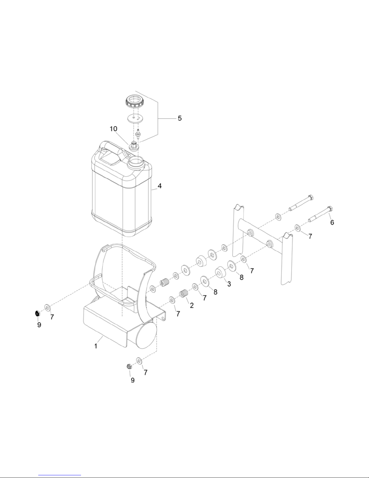
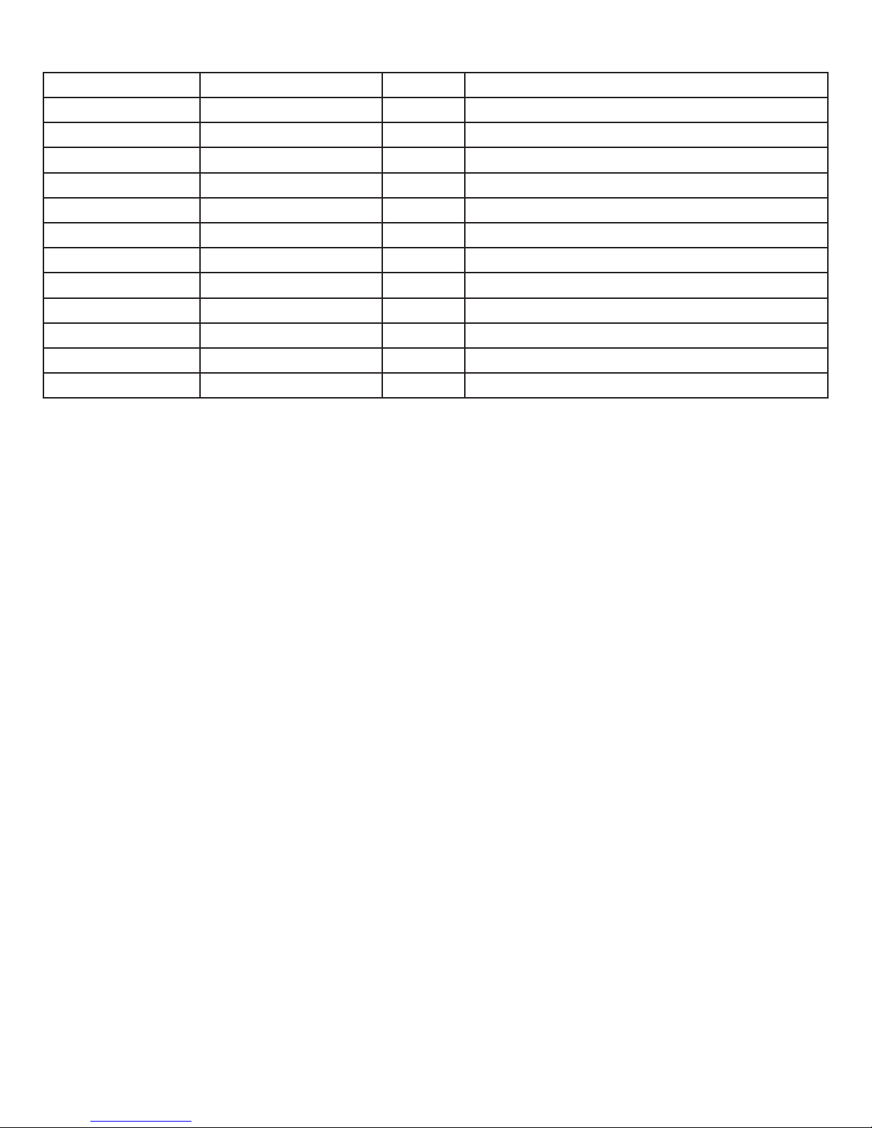
ITEM NO PART NUMBER QTY DESCRIPTION
1 2000 1 CAGE ASSY, BOTTLE HOLDER
2 2024 2 SPRING, BOTTLE HOLDER
3 2023 2 DAMPNER, RUBBER
4 2019 1 BOTTLE, CARTRIDGE, 3 GAL
5 2018 1 BOTTLE CAP, ASSY
6 2020 2 SCREW, 1/2-13 X 4-3/8",HH, STL, ZNPLT
7 2022 10 WASHER, NYLON, CAGE
8 2021 4 WASHER, 5/8ID X 1-3/4OD X .134L, FLT,
9 2025 2 NUT, 1/2-13 HEXTHIN NYLOCK STL ZNPLT
10 2017 1 STRAINER, SOLUTION BOTTLE
20
Page 21
PARTS
21
Page 22
PARTS
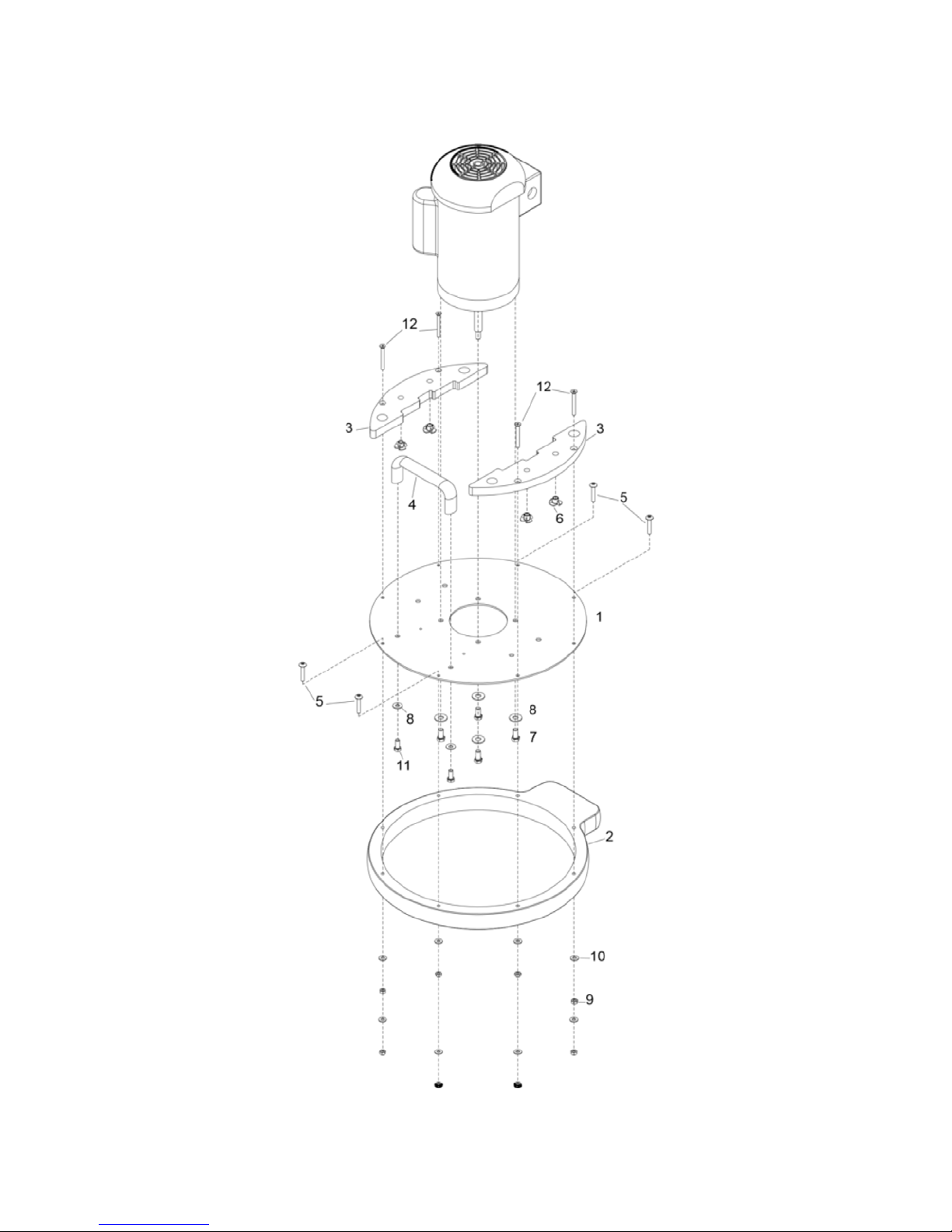
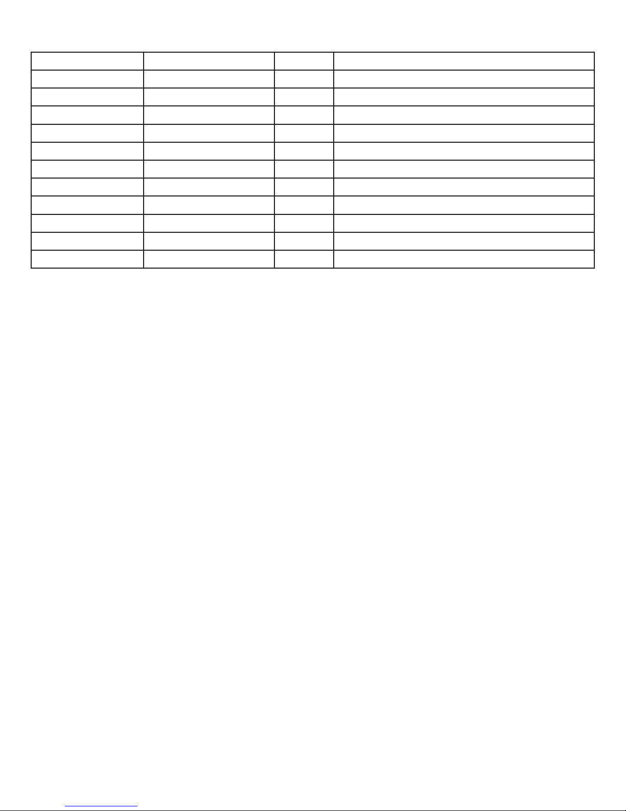
ITEM NO PART NUMBER QTY DESCRIPTION
1 3000 1 PLATE, MOTOR MOUNT
2 3001 1 BUMPER SET
3 3045-14 2 PLATE, BASE, WEIGHT
4 3004 1 HANDLE, BASE
5 3002 4 SCREW, 1/4-20 X 1-1/2", PHTRH,SS
6 3045-06 4 NUT, 1/4-20 X 5/16, TEE, 4 PRONG, ZNPLT
7 3034 4 SCREW,3/8-16 X 3/4",HH, STL, GRD8, YL,
8 3035 6 WASHER, 3/8, FLAT
9 3003 8 NUT, 1/4-20, HEX, LK, STL ZNPLT
10 3003-02 8 WASHER, 1/4 ID X 5/8 OD, STL, PLT
11 3006 2 SCREW, 5/16-18 X 3/4",HH, STL, ZNPLT
12 3045-04 4 SCREW, 1/4-20 X 2-1/4", PHFLH, ZNPLT
22
Page 23
PARTS
23
Page 24
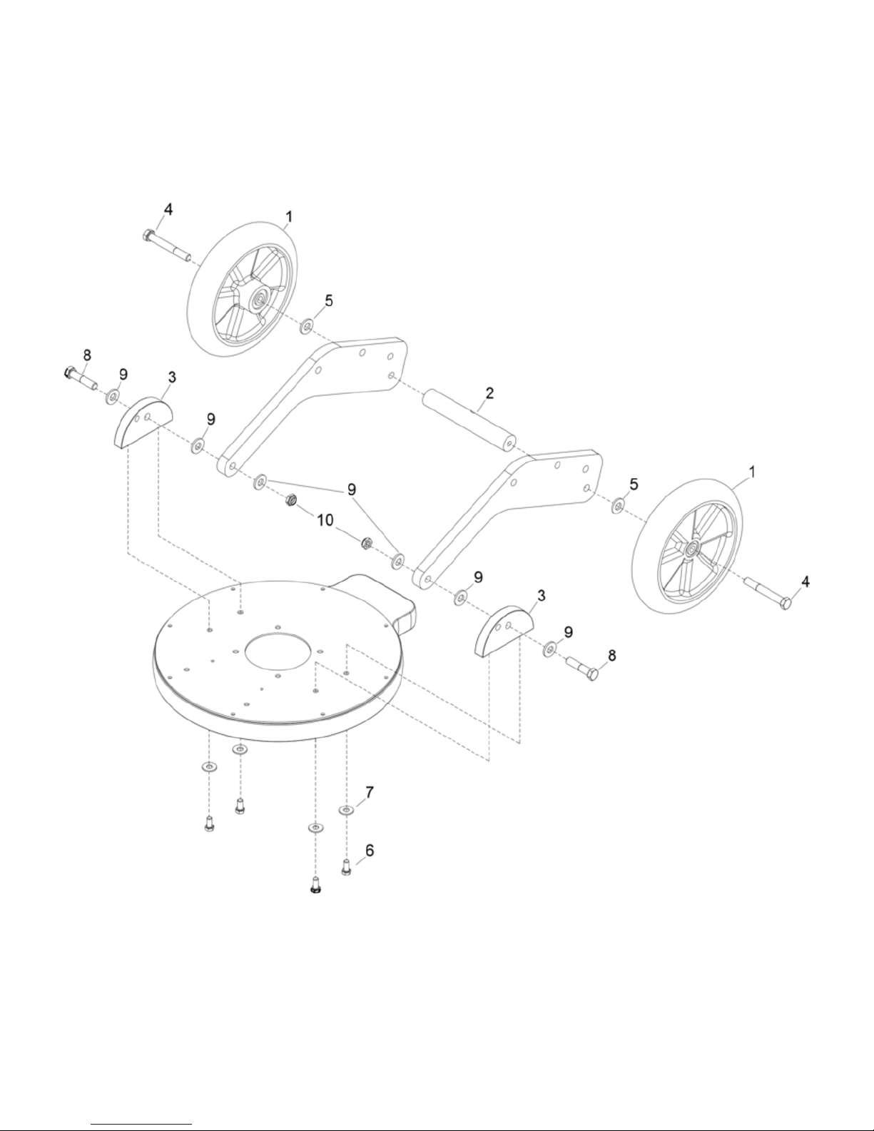
PARTS
ITEM NO PART NUMBER QTY DESCRIPTION
1 4003 2 WHEEL, 10”
2 4002 1 ROD, WHEEL
3 - 1 3007-051 1 LEFT EAR
3 - 2 3007-052 1 RIGHT EAR (with pin)
4 4005 2 SCREW, 1/2-13 X 3-3/4",HH, STL, ZNPLT
5 4004 2 WASHER, NYLON, WHEEL
6 3034 4 SCREW,3/8-16 X 3/4",HH, STL, GRD8, YL,
7 3008 4 WASHER, 3/8, FLAT
8 4009 2 SCREW, 1/2-13 X 2-1/4",HH, STL, ZNPLT
9 4010 6 WASHER, NYLON, ARMS TO EAR
10 4011 2 NUT, 1/2-13 HEXTHIN NYLOCK STL ZNPLT
24
Page 25
-1
PARTS
-2
25
Page 26
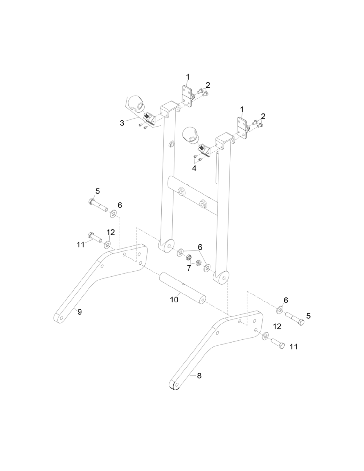
PARTS
ITEM NO PART NUMBER QTY DESCRIPTION
1 1001 2 HINGE, HANDLE
2 1002 8 SCREW, 5/16-24 X 1/2",HHMS, STL, ZNPLT
3 1003-10 2 LATCH, LOWER ASM, HANDLE
4 1003-12 4 SCREW, 10-32 X 1/4",SCHCS, STL, ZNPLT
5 1019 2 SCREW, LOWER HANDLE
6 1021 4 WASHER, NYLON
7 1020 2 NUT, 1/2-13 HEXTHIN NYLOCK STL ZNPLT
8 4001 1 PLATE, ARMS, LIFT, LH
9 4000 1 PLATE, ARMS, LIFT RH
10 4006 1 ROD, BRACE
11 4008 2 SCREW, 1/2-13 X 2",HH, STL, ZNPLT
12 4007 2 WASHER, NYLON, ARM SUPPORT
26
Page 27
PARTS
27
Page 28
PARTS
ITEM NO PART NUMBER QTY DESCRIPTION
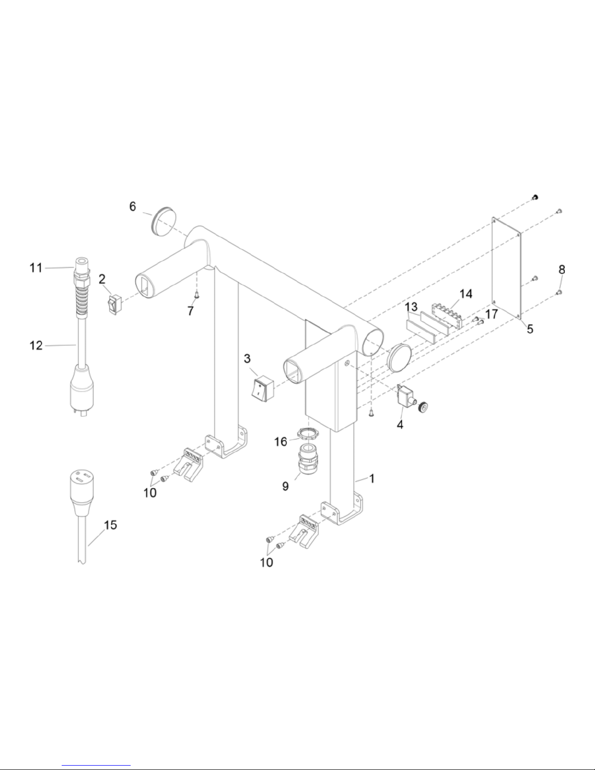
1 1000-06U 1 HANDLE ASM, UPPER, W/ELEC BOX
- 3028 1 HARNESS, MAIN HANDLE
2 1007 1 SWITCH, DP, 2POS, ROCKER SPR
- 1008 1 HARNESS, SPRAYER SWITCH
3 1005-03 1 SWITCH, DP POS, ROCKER
- 1006 1 HARNESS, ON/OFF SWITCH
4 1010 1 BREAKER, 20A 125/250VAC 32VDC
5 1011 1 PLATE, COVER, ELECTRICAL BOX
6 1015 2 COVER, TUBE, HANDLE
7 1016 2 SCREW, 6-20 X 3/8",PHPNH, STL, ZNPLT
8 1012 4 SCREW, ELECT BOX
9 1013 1 STRAIN RELIEF, ELEC BOX
10 1003-12 4 SCREW, 10-32 X 1/4",SCHCS, STL, ZNPLT
11 1018 1 STRAIN RELIEF, POWER CORD
12 1017 1 POWER CORD, HANDLE
13 1034 1 VELCRO, TERMINAL SWITCH
14 1009 1 TERMINAL SWITCH
15 1033 1 POWER CORD, 50’ 110V
16 1014 1 NUT, 1/2”, CORD GRIP
17 1032 2 SCREW, 8-32 X 3/8", SLTDHH, SS
28
Page 29
PARTS
29
Page 30
PARTS
ITEM NO PART NUMBER QTY DESCRIPTION
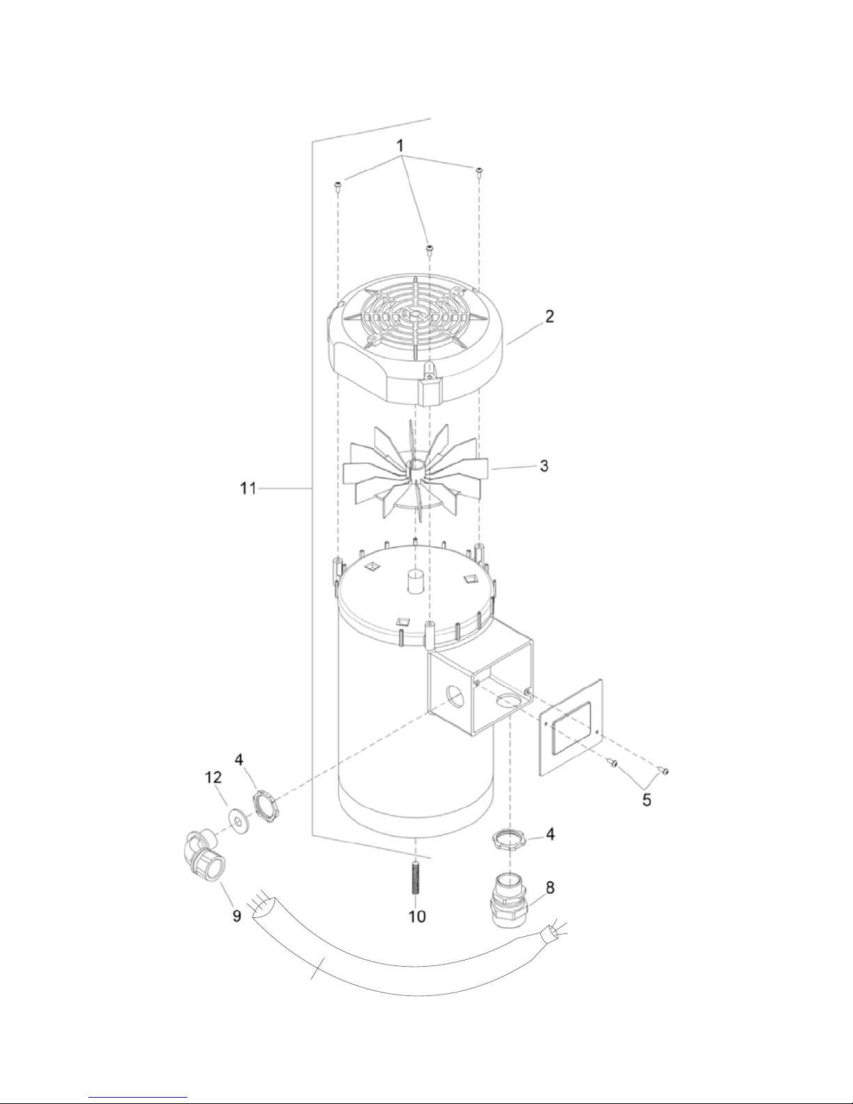
1 3023-05 3 TBD
2 3023-04 1 COVER, FAN MOTOR
3 3023-03 1 FAN, MOTOR
4 3030 2 NUT, 3/4”, CONDUIT
5 3023-06 2 SCREW, MOTOR LID
6 3032 1 CORD, BLUE PLUG, 100-120V
7 3033 1 CORD, BLACK PLUG, 100-120V
8 3031 1 CORD GRIP, 3/4", MOTOR
9 3029 1 CORD GRIP, 90 DEG, MOTOR
10 3024 1 SCREW, 3/8-24 X 1-1/2" SCH, SET, BLKOX
11 3023 1 MOTOR, 110/220V, 1750RPM
12 3023-02 1 WASHER, CORD GRIP, SERRATED
13 1 BODY CORD
30
Page 31
PARTS
13
31
Page 32
PARTS
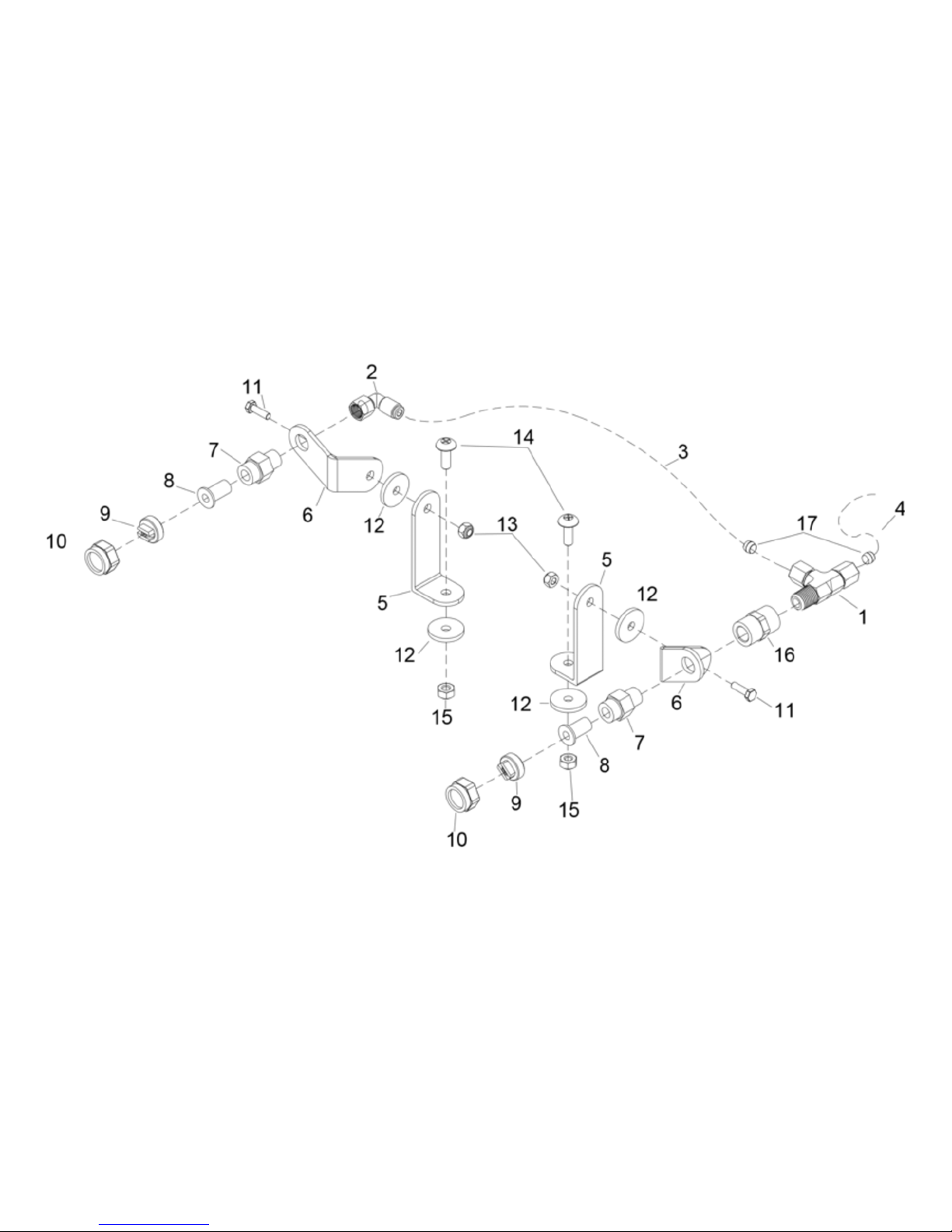
ITEM NO PART NUMBER QTY DESCRIPTION
1 3019 1 FITTING, TEE, SPRAY NOZZLES
2 3021 1 FITTING, 90, SPRAY NOZZLES
3 3022 1 HOSE, SPRAY NOZZLES
4 3022-01 1 HOSE, SPRAY NOZZLES CAGE
5 3009 2 PLATE, ANGLE, NOZZLE BASE
6 - 1 3010-001 1 SPRAY BRACKET, TOP LEFT
6 - 2 3010-002 1 SPRAY BRACKET, TOP RIGHT
7 3016 1 COUPLER, FILTER
8 3015 2 STRAINER, CHECK VALVE
9 3014 2 NOZZLE, SPRAYER
10 3017 2 NOZZLE RETAINER
11 3011 2 SCREW, 10-32 X 3/4", HXUNS, ZNPLT
12 3013 2 WASHER, SPRAY JET ARM
13 3012 2 NUT, 10-32 HEX NYLOCK STL GR2 ZNPLT
14 3036 2 SCREW, 1/4-20 X 3/4", PHTRH, SS
15 3037 2 NUT, 10-32 HEX NYLOCK STL GR2 ZNPLT
16 3020 1 COUPLER, NOZZLE BASE PLATE
17 3019-01 2 SLEEVE, COMPRESSION, CON
32
Page 33
PARTS
-1
-2
33
Page 34

PARTS
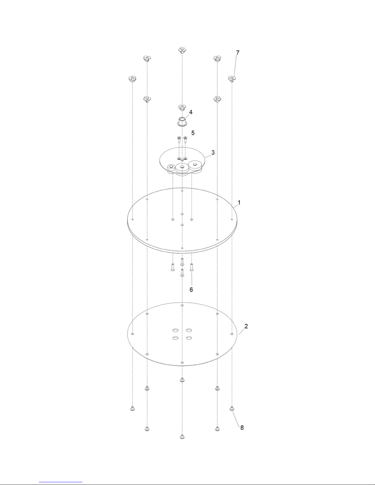
ITEM NO PART NUMBER QTY DESCRIPTION
1 3038 1 DRIVER, DISK, 15”
2 3040 1 DRIVER, VELCRO PLATE, 15”
3 3026 1 ASSY, COUNTERWEIGHT, 17 DISK
4 3025 1 SHAFT SUPPORT
5 3026-17 2 SCREW, 1/4-20 X 3/4, PHFLHMS, SS
6 3047 4 SCREW, 1/4-20 X 1", PHFLH, SS
7 3043 8 NUT, 1/4-20 X 5/16, TEE, 4 PRONG, ZNPLT
8 3042 8 SCREW, 1/4-20 X 3/8", PHTRH, SS
34
Page 35
PARTS
35
Page 36
PARTS
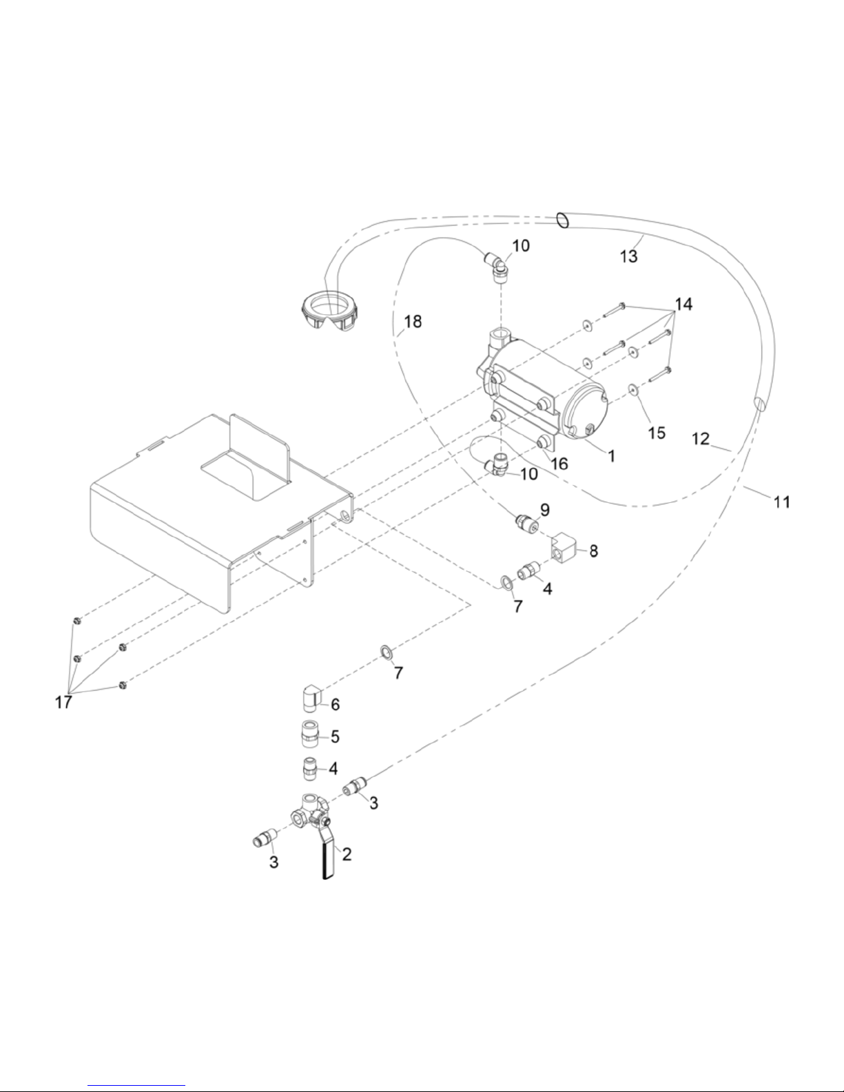
ITEM NO PART NUMBER QTY DESCRIPTION
1 2010 1 PUMP, 90PSI, 120V
2 2008 1 VALVE, FLOW CONTROL, 3-WAY
3 2008-01 2 COUPLER, QD, FLOW CONTROL
4 2008-02 2 NIPPLE, 1/4”, HEX
5 2008-03 1 COUPLER, FLOW CONTROL
6 2007 1 ELBOW, 1/4”, 90
7 2000-05 2 WASHER, 1/2ID X 3/4" OD, DSP, ZNPLT
8 2008-04 1 FITTING, ELBOW, 1/4”, 90
9 2016 1 FITTING, GUEST, STRAIGHT
10 2011 2 FITTING, GUEST, 90
11 2015-01 1 HOSE, 1/4”, BOTTLE CARTRIDGE
12 2015 1 HOSE, 3/8”, BOTTLE CARTRIDGE
13 2015-02 1 HOSE, BOTTLE CARTRIDGE ASSY
14 2012 4 SCREW, 6-32 X 1-1/4", HEXFLGH, ZNPLT
15 2014 4 WASHER, PUMP MOUNT
16 2010-02 4 GROMMET, DAMPNER, PUMP
17 2013 4 NUT, 6-32, HEX NYLOCK STL ZNPLT
18 2004 1 HOSE, 1/4”, PUMP CAGE
36
Page 37
PARTS
37
Page 38
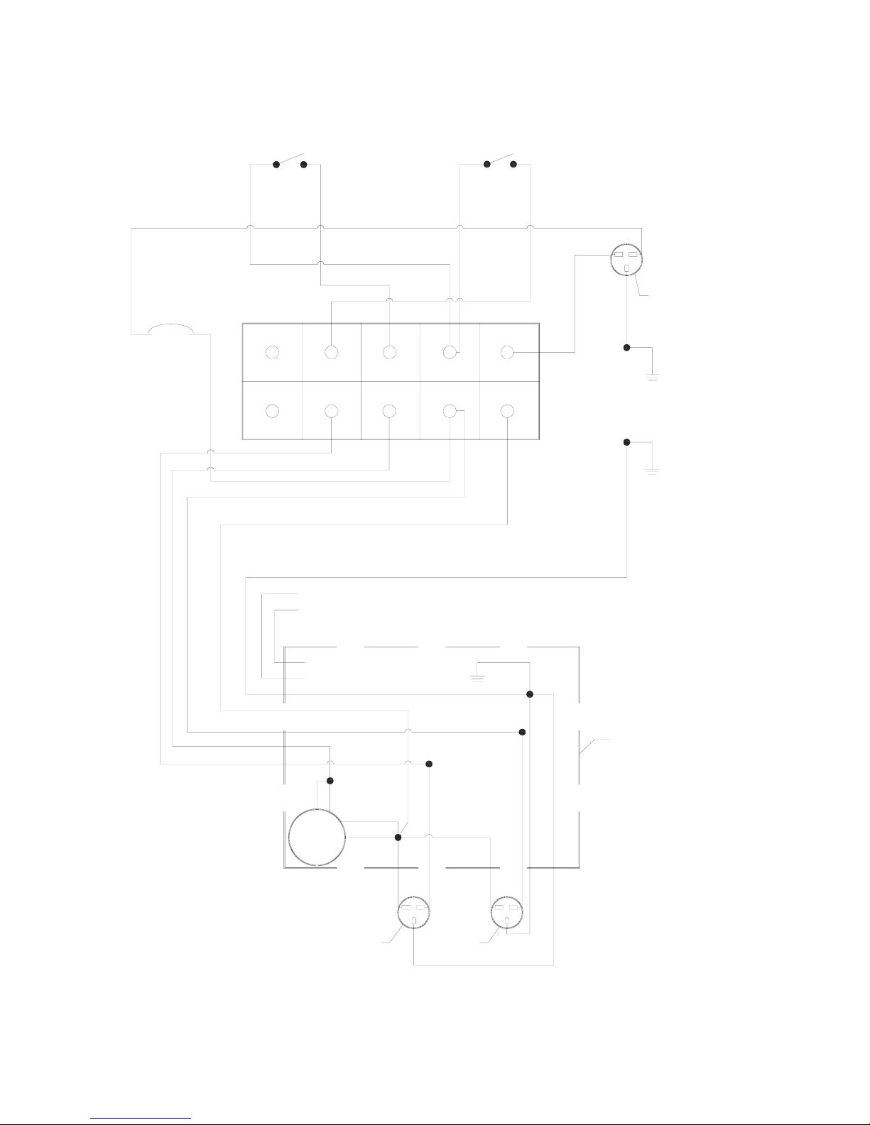
WIRING DIAGRAM
SPRAY SWITCHON/OFF SWITCH
Circuit Breaker
BLK
4 (RED)
1 (BLK)
3 (BLU)
1 (BLK)
2 (WHT)
2 (WHT)1 (BLK)2 (WHT)
5(YLW) No Connection (Insulated)
6 (BRN) No Connection (Insulated)
Terminal Strip
inside handle
wiring box
Ground
WHT
BLK
Power Cord
from Wall
Ground
Ground
38
YLW
BLK
Motor
Housing
Wires
BLU
ORG
WHTWHT
Pump Plug Extra Plug
BLK
Ground
Ground
Motor Wiring Box
BLK
Ground
Page 39

NOTES
39
 Loading...