

Page 1

2019
OPERATING MANUAL
Page 2
WARRANTY
All ORBOT equipment has been carefully tested and inspected at our USA factory. ORBOT
SLiM machines are guaranteed for one year from the date of original purchase against
defects or workmanship made during manufacture. Within the guarantee period we
undertake at our discretion, to repair or replace any part found to be defective, free of
charge to the purchaser with subject to the following conditions:
Claims made under the terms of the guarantee must be supported by the original invoice
issued at the time of sale along with the machine serial number.
For claims under this guarantee contact the supplier from whom you’ve purchased the
product who will arrange the appropriate action. Do not initially return the product as this
could lead to transit damage.
Neither ORBOT nor its distributors will be held responsible for any incidental or
consequential loss.
This guarantee does not cover:
• Periodic maintenance, repair or replacement of parts due to normal wear and tear.
• Damage caused by accident, misuse or neglect, re or the tting of other than genuine
ORBOT parts. • Defects in other than genuine ORBOT parts, repairs, modications or
adjustments made by other than an ORBOT service engineer or authorized service dealer.
• Costs and risks of transport relating directly or indirectly to the guarantee of this product.
• Consumable items such as brushes, drivers, velcro discs, gliders, pads and so forth.
ORBOT has a policy of continual product development and we reserve the right to alter
specications without prior notice.
MACHINE DATA
Model:
Serial:
Date of Purchase:
Dealer:
Address:
Phone Number:
Sales Representative:
EC Declaration of Conformity
Machine Type: Floor Model: Orbot Sprayborg
This Machine is in conformity with the following EU directives:
- Machinery Directive: 2006/42/EC
- Electro Magnetic Compatibility Directive: 2004/108/EC
- In conformity with 2006/95/EC
Applied harmonized standards: EN 60335-1, EN 60335-2-67
HOS GmbH
Hruby Orbital Systems
Kleiststraße 7, 10787 Berlin
2
Date: 02/08/2010
Jeffrey Hruby CEO
Page 3

TABLE OF CONTENTS
Warranty
EC Declaration of Conformity
How to Use This Manual
Safety - Important Instructions
Technical Details
Operation
Unpacking
Solution Tank
Pad/Brushes
Power Switch
Battery
Handle Position
Operating Machine / Operating Option
Spray System
Lifting and Handling
Storage
Accessories and Applications
Pad Driver
SuperZorb Pad
MicroFiber Pad
UltraLift Pad
AkwaStrip Pad
StoneFlash Pad
Carpet Brush
Tile & Grout Brush
2
4
5 - 7
8
9 - 16
9
10
11
12
13
Maintenance
Cleaning the Machine
Checking the Machine
SLiM Cleans in Small Spaces
Part Diagrams and Part Lists
Wiring Diagram
14
15 - 22
23
3
Page 4

HOW TO USE THIS MANUAL
This manual contains the following sections:
• How to Use This Manual
• Safety
• Operations
• Maintenance
• Parts List
The HOW TO USE THIS MANUAL
section will tell you how to nd important
information for ordering correct repair
parts.
Parts may be ordered from authorized
dealers. When placing an order for
parts, the machine model and machine
serial number are important. Refer to the
MACHINE DATA box which is lled out
during the installation of your machine.
The MACHINE DATA box is located on the
inside of the front cover of this manual.
The model and serial number of your
machine is located on the left side of the
handle, from the operators perspective.
The SAFETY section contains important
information regarding hazardous or unsafe
practices of the machine. Levels of hazards
are identied that could result in product
damage, personal injury, or severe injury
resulting in death.
The OPERATIONS section is to familiarize
the operator with the operation and
function of the machine.
The MAINTENANCE section contains
preventive maintenance to keep the
machine and its components in good
working condition. They are listed in this
general order:
The PARTS LIST section contains assembled
parts illustrations and corresponding parts
list. The parts lists include a number of
columns of information:
• REF – column refers to the reference
number on the parts illustration.
• PART NO. – column lists the part number
for the part.
• PRV NO. – reference number.
• QTY – column lists the quantity of the part
used in that area of the machine.
• DESCRIPTION – column is a brief
description of the part.
• SERIAL NO. FROM – If this column has
an (*) and a Reference number, see the
SERIAL NUMBERS page in the back of
your manual. If column has two asterisk
(**), call manufacturer for serial number.
The serial number indicates the rst
machine the part number is applicable
to. The main illustration shows the most
current design of the machine. When a
boxed illustration is shown, it displays the
older design.
• NOTES – column for information not
noted by the other columns.
NOTE: If a service or option kit is installed
on your machine, be sure to keep the KIT
INSTRUCTIONS which came with the kit. It
contains replacement parts numbers needed
for ordering future parts.
NOTE: The manual part number is located
on the lower left corner of the front cover.
• Storage
• Maintenance
• Troubleshooting
4
Page 5

WARNING
SAFETY
IMPORTANT SAFETY INSTRUCTIONS
When using this machine, basic precautions must always be followed,
including the following:
READ ALL INSTRUCTIONS BEFORE USING THIS MACHINE.
To reduce the risk of re, electric shock, or injury:
• Use only indoors. Do not use outdoors or expose to rain.
• Use only as described in this manual. Use only manufacturers recommended components
and attachments.
• If the machine is not working properly, has been dropped, damaged, left outdoors, or
dropped into water, return it to an authorized service center.
• Do not operate the machine with any openings blocked. Keep openings free of debris that
may reduce airow.
• Machine can cause a re when operating near ammable vapors or materials. Do not
operate this machine near ammable uids, dust or vapors.
• This machine is suitable for commercial use such as: in hotels, schools, hospitals, factories,
shops, and ofces for more than normal housekeeping purposes.
• Maintenance and repairs must be done by qualied personnel.
• During operation, use caution around other persons, especially children.
• The machine shall only be operated by instructed and authorized persons.
• When leaving unattended, unplug the machine.
• Do not handle the plug or machine with wet hands.
• Do not unplug machine by pulling on cord. To unplug, grasp the plug and not the cord.
• Do not use with damaged cord or plug. Follow all instructions in this manual concerning
grounding the machine.
• Do not pull or carry by cord, use cord as a handle, close a door on cord, or pull cord
around sharp edges or corners.
• Do not pull/run machine over cord. Keep cord away from heated surfaces.
• Connect to a properly grounded outlet. See Grounding Instructions.
• If the supply cord is damaged it must be replaced by an authorized service agent.
• Unplug before cleaning or servicing.
• Operational hazard may occur when running the machine over the supply cord.
• This appliance has been designed for use with pads specied by the manufacturer. The
tting of other pads may affect its safety.
• This machine is for dry use only and shall not be used or stored outdoors in wet conditions
• Moving Parts - To reduce the risk of injury, unplug before servicing.
READ AND SAVE THESE INSTRUCTIONS
5
Page 6

WARNING
CAUTION
SAFETY
The following symbols are used throughout this guide as indicated in their descriptions:
HAZARD INTENSITY LEVEL
There are three levels of hazard intensity identied by signal words -WARNING,
CAUTION, and FOR SAFETY. The level of hazard intensity is determined by the following
denitions:
WARNING - Hazards or unsafe practices CAN result in severe personal injury or death.
CAUTION - Hazards or unsafe practices which could result in minor personal injury or
product or property damage.
FOR SAFETY: To Identify actions which must be followed for safe operation of equipment.
Report machine damage or faulty operation immediately. Do not use the machine if it is not
in proper operating condition. The following is information that signals some potentially
dangerous conditions to the operator or the equipment. Read this information carefully.
Know when these conditions can exist. Locate all safety devices on the machine. Please take
the necessary steps to train the machine operating personnel.
FOR SAFETY:
DO NOT OPERATE MACHINE:
• Unless trained and authorized.
• Unless Operation Guide is read and understood.
• In ammable or explosive areas.
• In areas with possible falling objects.
WHEN SERVICING MACHINE:
Avoid moving parts. Do not wear loose clothing, jackets, shirts, or sleeves when working on
the machine. Use only manufacturer approved replacement parts.
6
Page 7

SAFETY
HYBRID GROUNDING INSTRUCTIONS 120V (when applicable)
THIS PRODUCT IS FOR COMMERCIAL USE ONLY
ELECTRICAL:
In USA this machine operates on a 15 amp nominal 120V, 60 hz, A.C. power circuit. The
amp, hertz, and voltage are listed on the data label found on each machine. Using voltages
above or below those indicated on the data label will cause serious damage to the motors.
GROUNDING INSTRUCTIONS:
This appliance must be grounded. If it should malfunction or break down, grounding
provides a path of least resistance for electric current to reduce the risk of electric shock.
This appliance is equipped with a cord that has an equipment-grounding conductor and
grounding plug. The plug must be inserted into an appropriate outlet that is properly
installed and grounded in accordance with all local codes and ordinances.
For use on a nominal 120 volt circuit with a grounded plug that looks like the plug in
FIGURE A. A temporary adaptor that looks like the adaptor in FIGURE C may be used to
connect this plug to a 2-pole receptacle as shown in FIGURE B, if a properly grounded
outlet is not available. The temporary adaptor should be used only until a properly
grounded outlet (FIGURE A) can be installed by a qualied electrician. The green colored
rigid ear, lug or similar that extends from the adaptor must be connected to a permanent
ground such as a properly grounded outlet box cover. Whenever the adaptor is used, it
must be held in place by a metal screw.
WARNING
Improper connection of the
equipment-grounding conductor
can result in electric shock. Check
with a qualied electrician or
service person if you are in doubt
as to whether the outlet is properly
grounded. Do not modify the plug
provided with the appliance - if it
will not t the outlet, have a proper
outlet installed by a qualied
electrician.
SAFETY LABEL LOCATION
If at any time the safety labels become illegible, contact your authorized representative for
prompt replacement.
7
Page 8

TECHNICAL DETAILS
ITEM SPECIFICATIONS
Motor 36 V/330W - DC, 3000 RPM, 59 dB with protective cover
Dual Speed 3000 RPM (Orbital), 120 RPM (Rotational)
Base Diameter 11” (27.9 cm)
Wheel Diameter 4” (10.16 cm)
Solution Tank Capacity 3/4 Gallon (2.84 L)
Pump 58 PSI (4 BAR)
Noise Level 59 dB
Height 47” (119 cm)
Weight 28 Lbs/12.7 Kg (+6 lbs/2.7kg w/tank & battery)
Battery (BMS) Lithium-ion 36V/40W/6Ah (Battery Management System)
Run Time Up to 45 Minutes (depending on oor type/pad)
Charge Time 90 Minutes
8
Page 9
Unpacking
CAUTION
WARNING
Open shipping box (both sides). Remove
packaging material and roll machine out of
the box.
Solution Tank
Disconnect the quick-connect tting located
at the bottom of the solution tank. Remove
solution tank by pulling away from the handle
frame. Add water or cleaning detergent of
choice. Snap solution tank onto frame.
Reconnect the quick-connect tting.
Ensure solution tank cap is securely fastened
to avoid leaks and spills.
Pads/Brushes
Choose an Orbot pad or brush of choice to
clean or restore the desired oor.
Place under the hook pad driver BEFORE
powering on machine.
To remove, simply peel off.
OPERATION
Power Switch
Turn power switch to the OFF position located
at the top of the handle. The power switch will
illuminate when powered ON.
Battery
Insert the battery into the battery tray located
inside the base housing cover.
Ensure to completely lock the battery into
position until you hear a click sound.
To remove the battery, release the battery
lever and pull out. You can use your right
hand to help push the battery out of the tray.
Always remove battery and immediately
charge to avoid damage.
9
Page 10
OPERATION
Handle Position
Before powering ON the machine, lower the
handle into a comfortable position by pulling
out the pull-pin lever located on the lower left
side of the handle fork.
Operating Machine
Turn power switch on, and begin to maneuver
the machine over the oor surface.
The machine can be moved in all directions.
When cleaning carpet, the machine is best
moved forward to backwards, while spraying
only forward.
Operating Option
To increase operator comfort, the wheel
kit can be lowered down onto the oor by
releasing the pull-pin lever and choosing the
desired height.
Spray System
To apply water or detergent to the oor
surface, press the spray switch located on the
top right side of the handle.
System Light Indicators
(Located on Top of Motor Cover)
Blue lights:
• One Blue Light: Low Battery Level
• Two Blue Lights: Medium Battery Level
• Three Blue Lights: Full Battery Level
Red light:
• Machine is working over full load capacity.
Run times will lessen.
Green light:
• Machine is working under light load
capacity. Run times will increase.
10
Page 11
HANDLING & STORAGE/ACCESSORIES & APPLICATIONS
CAUTION
WARNING
CAUTION
WARNING
Lifting & Handling
To lift the machine into a vehicle, use handle
located on fork. To lift the machine up stairs,
lower the wheel kit to 90 degrees.
Storage
Always keep machine stored in the upright
position. Do not store brushes under pad
driver when not in use.
_______________________________________
ACCESSORIES AND APPLICATIONS
_______________________________________
Never store the accessories in wet conditions.
Keep away from extreme heat and from
chemicals.
Pad Driver
To replace the pad driver, remove the 4
screws using a #3 Phillips/Star screwdriver.
Using the incorrect screwdriver can result in
stripping the screw head.
Pad drivers should be replaced when the hook
material becomes clogged with excess lint and
debris.
It is important to operate the machine using
clean pad drivers to ensure optimal cleaning
performance. When excess clogging occurs
from lint and debris, the hook tensile strength
is reduced which leads to damaged pads and
brushes.
Never place driver onto oor surface without
a pad or brush.
11
Page 12
OPERATION
SuperZorb Pad
Our exclusive SuperZorb pad is made of a
special cotton and polyester blend. One of the
primary components that help to extract an
essential amount of soil from the carpet bers.
They also play an important role to achieve
fast dry times. SuperZorb pads can be used
on both sides. SuperZorb pads are machine
washable. Allow to air dry.
SuperZorb pads are also great to be used to
power mop hard oors.
MicroFiber Pad
Use for cleaning all carpets and hard oors.
Best used for high friction oor types. Choose
over SuperZorb Pads when laundry machines
are limited. Can be easily washed by hand.
UltraLift Pad
The UL pads are used to remove stubborn
stains and grease trapped in microporous
hard oors such as tile, stone, VCT/vinyl,
concrete, wood, epoxy, and more.
Use with water or mild detergents.
AkwaStrip Pad
The AkwaStrip pad is a chemical free
stripping pad made of a unique material lled
with diamonds. Used for deep cleaning and
to remove wax off of vinyl, VCT, linoleum,
wood, safety tiles and more. Used on both
sides. Thoroughly rinse with clean water after
use.
12
Page 13
StoneFlash Pads
CAUTION
CAUTION
StoneFlash pads are part of a 5 step system
for grinding, honing and polishing marble,
terrazzo, travertine, limestone and more.
Carpet Brush
To lift carpet ber piles.
Use for extra scrubbing power to release
stubborn stains.
Also use on hard or rubber oors to release
dirt from small cracks, crevices, and pores.
OPERATION
Do not store brushes under the machine. As
a result, bristles will become damaged and
deformed.
Tile & Grout Brush
Use for cleaning hard oor tiles, grout lines,
pores, cracks, and crevices.
Do not store brushes under the machine. As
a result, bristles will become damaged and
deformed.
13
Page 14

MAINTENANCE
COMMON MAINTENANCE
Cleaning the Machine
• Always maintain a clean machine
to preserve it’s presence and optimal
performance.
• Maintain clog free hook pad drivers
to maximize cleaning performance and
eliminate damage to pads and brushes.
Checking the Machine
• Check counter weight bearing to ensure
optimal performance and minimal vibration.
• Check for any loose nuts and bolts to
minimize vibration.
• Check pull lever pins for any loose
fasteners.
• Check solution tank lters to ensure
maximum solution ow.
SLiM Cleans in Small Spaces
• Ease of cleaning in tight and narrow spaces
such as under chairs.
• Ease of cleaning within hard to reach spots
in bathrooms.
• Ease of carrying up stairs as well as
cleaning them.
• Also, planes, trains, automobiles, etc. are
very hard to clean where the SLiM comes
in handy to assist in these areas. Plus many
more possible opportunities where most
cleaning machines are too large to get to
those small spaces.
14
Page 15

SOLUTION TANK ASSEMBLY
PARTS
ITEM NO PART NUMBER DESCRIPTION QTY.
1 01-221 SOLUTION TANK 1
2 01-222 FILL TANK 1
3 01-223 TANK FILTER ADAPTER ASSEMBLY 1
4 01-224 MALE QUICK-CONNECT 1
5 01-225 TANK SOLUTION HOSE 1
6 01-226 TANK TAB SCREW, 1/4”-20 X 3/4” 2
7 01-227 TANK TAB 2
15
Page 16

PARTS
HANDLE / FRAME ASSEMBLY
16
Page 17
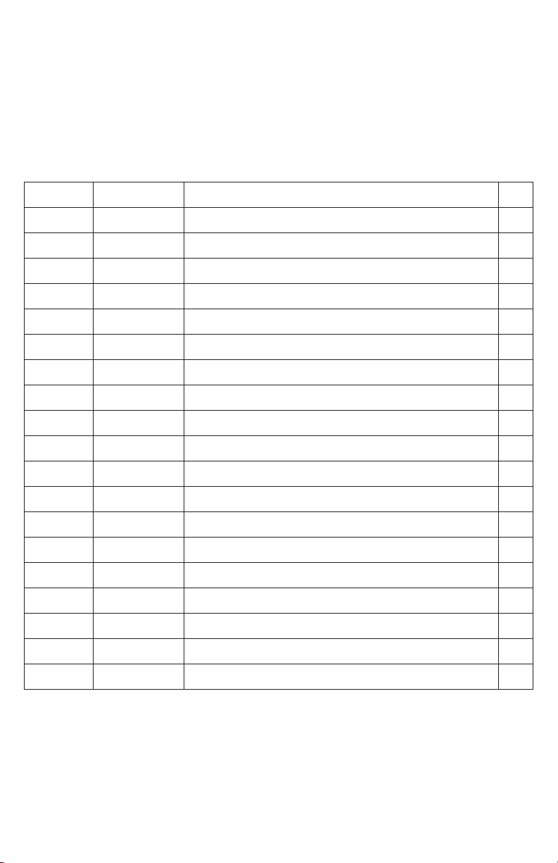
PARTS
HANDLE / FRAME ASSEMBLY
ITEM NO PART NUMBER DESCRIPTION QTY.
1 01-201 WELDED ALUMINUM HANDLE ASSEMBLY 1
2 01-202 15 AMP CIRCUIT BREAKER 1
3 01-203 RUBBER, TANK MOUNT STOP 2
4 01-204 PUMP MOUNT SCREW 6-32 X 7/8” 4
5 01-205 HANDLE FORK MOUNTING SCREW, 3/8-16 X 1-3/8” 2
6 01-206 HANDLE FORK MOUNTING WASHER 3/8” 4
7 01-207 HANDLE FORK SPACER 2
8 01-208 HANDLE FORK INNER MOUNTING WASHER 1/2” 4
9 01-209 HANDLE FORK MOUNTING NUT 3/8” 2
10 01-210 PULL PIN MOUNTING SCREW 10-24 X 5/8” 2
11 01-211 PULL PIN 1
12 01-212 REED SWITCH, MAGNET, SCREW, 6-32 X 5/8” 2
13 01-213 REED SWITCH, MAGNET 1
14 01-214 RUBBER, TANK MOUNT STOP, NUT, 8-32 2
15 01-215 PLASTIC CAPS, TUBE 2
16 01-216 TERMINAL BOX COVER SCREW, 8-32 X 3/16” 4
17 01-217 TERMINAL BOX COVER 1
18 01-218 SPRAYER SWITCH 1
19 01-219 POWER SWITCH 1
17
Page 18

PARTS
WHEEL KIT / PUMP ASSEMBLY
ITEM NO PART NUMBER DESCRIPTION QTY.
1 02-221 WHEEL, 3” 2
2 02-222 ALUMINUM WHEEL KIT FRAME 1
3 02-223 WHEEL KIT WASHER, NYLON, 3/8” ID X 3/4” OD 4
4 02-224 WHEEL KIT MOUNTING SCREW, 3/8”-16 X 1” 2
5 02-225 WHEEL KIT MOUNT 1
6 02-226 WHEEL KIT MOUNT SCREW, 10-24 X 5/8” 4
7 02-227 PULL PIN MOUNTING SCREW, 10-24 X 5/8” 2
8 02-228 PULL PIN 1
9 02-229 PUMP COVER SCREW 6-32 X 5/8” 4
10 02-230 PUMP MOUNT 1
11 02-231 PUMP CIRCUIT BOARD 1
12 02-232 PUMP 58 PSI / 4 BAR 1
13 02-233 PUMP COVER 1
18
Page 19
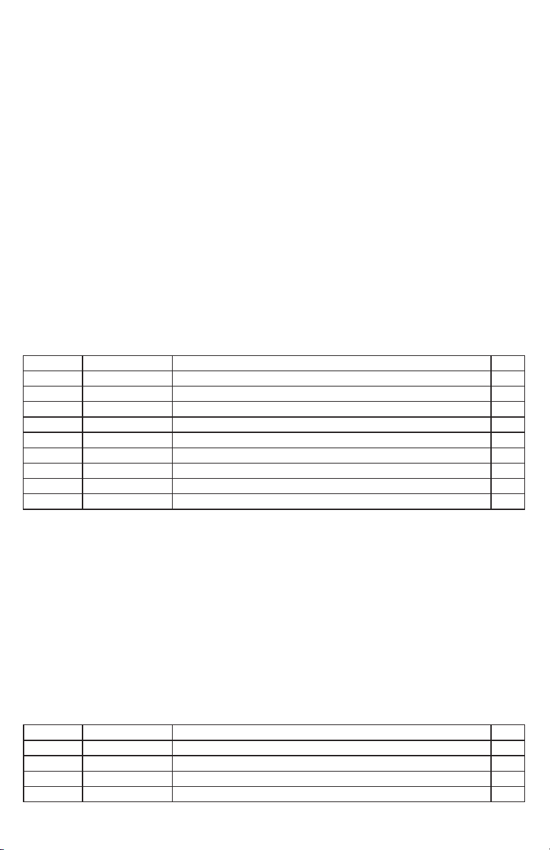
PARTS
SPRAY NOZZLE &
MOTOR COVER
ASSEMBLY
ITEM NO PART NUMBER DESCRIPTION QTY.
1 03-201 MOTOR COVER, SILVER 1
2 03-202 90° QUICK-CONNECT SPRAY FITTING 1
3 03-203 SPRAY JET BODY 1
4 03-204 CHECK VALVE STRAINER 1
5 03-205 SPRAY JET TIP 1
6 03-206 SPRAY JET CAP 1
7 03-207 FRONT MOTOR COVER MOUNTING SCREW, 1/4-20 X 5/8” 2
8 03-208 REAR MOTOR COVER MOUNTING SCREW, 1/4-20 X 1” 2
9 03-209 SPRAYER HOSE 1
BATTERY ASSEMBLY
ITEM NO PART NUMBER DESCRIPTION QTY.
1 03-211 BATTERY, 36V, 6AH 1
2 03-212 BATTERY FOAM BASE 1
3 03-213 BATTERY TRAY 1
4 03-214 BATTERY TRAY MOUNTING SCREW, 10-32 X 1-1/2” 4
19
Page 20

PARTS
BASE & DRIVER PLATE ASSEMBLY
20
Page 21
PARTS
BASE & DRIVER PLATE ASSEMBLY
ITEM NO PART NUMBER DESCRIPTION QTY.
1 03-221 WEIGHT KIT MOUNTING SCREW, 1/4-20 X 1-1/4” 4
2 03-222 WEIGHT PLATE 2
3 03-223 BUMPER THREADED INSERT 16
4 03-224 MOTOR, 36V / 330W, 3000 RPM, 59DB 1
5 03-225 MOTOR MOUNTING SCREW, 10-32 X 3/4” 4
6 03-226 BASE PLATE 1
7 03-227 SHAFT SUPPORT 1
8 03-228 BEARING ASSEMBLY MOUNTING SCREW, 1/4-20 X 3/4” 2
9 03-229 BEARING ASSEMBLY WASHER 1
10 03-230 BEARING ASSEMBLY 1
11 03-231 DRIVER ASSEMBLY 1
12 03-232 DRIVER MOUNTING SCREWS, 1/4-20 X 1” 4
13 03-233 LOWER BUMPER RING 1
14 03-234 COUNTER WEIGHT PLATE 1
15 03-235 UPPER BUMPER RING 1
16 03-236 EAR STOPPER PIN 1
17 03-237 WHEEL MOUNTING SCREW, 5/16” X 2-1/4” 2
18 03-238 WHEEL, 4” 2
19 03-239 WHEEL SPACER 2
20 03-240 WHEEL MOUNTING WASHER, 5/16” X 5/8” 2
21 03-241 WHEEL MOUNTING LOCK NUT, 5/16” 2
22 03-242 PULL PIN SLIDE MOUNTING SCREW, 10-24 X 3/8” 3
23 03-243 PULL PIN SLIDE 1
24 03-244 REED SWITCH, MAGNET MOUNTING SCREW, 6-32 X 3/8” 2
25 03-245 REED SWITCH, MAGNET 1
26 03-246 BASE MOUNTING WASHER, .281 OD, .734 X 1/16” 4
27 03-247 BASE MOUNTING SCREW, 1/4-20 X 1-1/2” 4
21
Page 22

PARTS
COMPLETE ASSEMBLY
22
Page 23

WIRING DIAGRAM ORBOT SLiM
23
Page 24

“Innovators in Orbital Floor Care”
3275 Corporate View, Vista, CA 92081, USA
P: 760-936-8054 | [email protected]
www.orbotusa.com
EXPERIENCE THE NEW METHOD to CLEAN ANY FLOOR!
 Loading...