

Orbit Merret OMX 333UNI Quick Start Manual
OMX 333UNI
SETTING
Selection of measuring type/mode
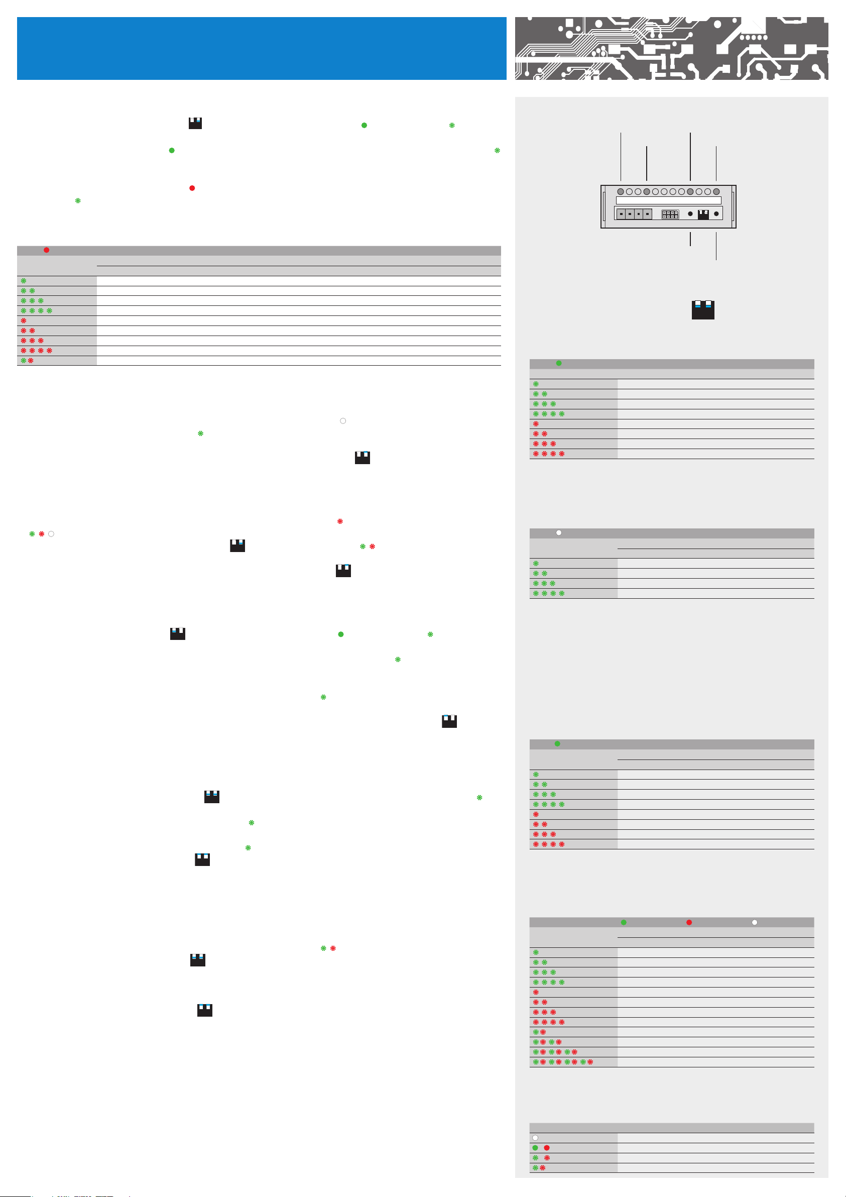
1. by switching dipswitch no. 2 to position „ON“ 12 programming mode is accessed - LED „Lo“ lights up and LED „Hi“ signals the
type of input by flashing (table 1)
2. change of input type, LED „Lo“ is green - by repeated pressing of button „Lo“ input types are accessed step by step and LED „Hi“
signals the type of input by flashing (table 1)
3. by pressing button „Hi“ our selection is confirmed and a next menu item can be accessed
4. setting the measuring range - LED „Lo“ is red
and LED „Hi“
signals the type of measuring range (table 2) or for input type „DU“ it is the setting of minimum (if the slider is in a
- by repeated pressing of button „Lo“ measuring ranges are accessed step by step
static position, then by pressing button „Lo“)
Tab. 2
LED „LO“
LED „HI“
MODE
PM DC T/C OHM Pt Ni Cu DU - calib. of min
±2 V ±30 mV B 0…100 Ω Pt 100 - Eu Ni 1 000/5 000 Cu 50/4285
±5 V ±60 mV E 0…300 Ω Pt 500 - Eu Ni 1 000/6 000 Cu 100/4285
±10 V ±1 V J 0…1,5 KΩ Pt 1 000 - Eu Ni 10 000/5 000 Cu 50/4260
0…20 mA ±20 V K 0…3 KΩ Pt 100 - Us Ni 10 000/6 000 Cu 100/4260
4…20 mA ±40 V N 0…24 KΩ Pt 50 - Ru
4…20 mA (Er) ±80 V R 0…30 KΩ Pt 100 - Ru
±90 mA S
±180 mA T
L
5. by pressing button „Hi“ our selection is confirmed and a next menu item can be accessed (if it exists for the given type), otherwise
there is return to type
6. setting of connection (only for type DU, OHM, Pt, Ni, Cu, T/C) - LED „Lo“ does not light up - by repeated pressing of button „Lo“
types of connection are accessed and LED „Hi“ signals the type of connection (table 3) or for type „DU“ setting the maximum
(if the slider is in a static position, then by pressing button „Hi“)
7. by pressing „Hi“ selected setting is confirmed and dipswitch no. 2 can be switched to „OFF“
12
LED „L2“
Tab. 1
LED „LO“
LED „HI“ TYPE
LED „Lo“
LED „L1“
L2 L1 Lo Hi
LED „Hi“
12
OM Link
Button
„Lo“
Button
Switch
12
PM
DC
T/C
DU
OHM
Pt
Ni
Cu
„Hi“
OFF
ON
Setting of Limits 1 (2)
1. after pressing button „Hi“ (for Limit 2 it is button „Lo“) red LED „L 1“ („L 2“) starts flashing and both LED “Lo” and “Hi” flash in cycles
2. set dipswitch no. 2 (for Limit L2 it is switch no. 1) to „ON“
, LED “Lo” an “Hi” flash in cycles
12
3. on the OMX 333 input set the sinal to the level required for the Limit to be actuated
4. select your setting by pressing the „Hi“ button and switch the dipswitch no. 2 to „OFF“
12
Setting of Analogue/Data output
1. by switching the dipswitch no. 1 to „ON“
of output by flashing (table 4) or the rate of analogue output (table 5)
2. by repeated pressing of button „Lo“ the types of analogue output are accessed (rychlosti) and LED „Lo“ signals the the type of
output (tab. 4) or the rate of data output (tab. 5)
3. by pressing „Hi“ the selected setting is confirmed and a next menu item can be accessed (only for further setting of data output)
4. by repeated pressing of „Lo“ button instrument‘s address can be set ang LED „Lo“ signals by flashing the address of OMX 333
(table 5) (this procedure only applies to setting of data output)
5. our setting is confirmed by pressing „Hi“ button and progarmming mode is exited by switching dipswitch no. to „OFF“
programming mode is accessed - LED „Hi“ lights up and LED „Lo“ signals the type
12
12
Changing analogue output (AO) range
1. OMX 333 AO is set by manufacturer. This procedure is for experienced users
2. by switching dipswitches no. 1 and no 2 to „ON“
3. to input terminals of OMX 333 connect signal of requested level which equals to minimum range of AO (for example 4 mA)
and by pressing „Lo“ button this value is recorded, LED „Lo“ fl ashes twice the normal rate
4. to input terminals of OMX 333 connect signal of requested level which equals to maximum range of AO (for example 20 mA)
and by pressing „Hi“ button this value is recorded, LED „Hi“ fl ashes t wice the normal rate
5. by switching dipswitches no. 1 and 2 to „OF F“
programming mode is accessed - LED „Lo“ and „Hi“ fl ash alternatively
12
programming mode is exitted
12
Tab. 3
LED „LO“
LED „HI“
CONNECTION
OHM/RTD T/C DU - calib of max
Int. 1
2-wire Int. 2
3-wire Ext. 1
4-wire Ext. 2
Cold junction compensation (CJC)
Int. 1 measurement of CJC on instrument’s terminals
Int. 2 measurement of CJC on instrument’s terminals and anti-serial connection
of referential T/C
Ext. 1 the entire system wokrs in a uninamous and constant temperature
Ext. 2 with a compensation box and referential T/C
Tab. 4
LED „HI“
LED „LO“
ANALOGUE OUTPUT
TYPE
0…2 V
0…5 V
0…10 V
±10 V
4…20 mA (Er)
4…20 mA
0…20 mA
0…5 mA
Restoration of manufacturer‘s /user settings
1. this is a good way how to return to the original manufacturer’s setting especially when making a mistake during the set
up process
2. by pressing buttons “Lo” and Hi” simultaneously for approx 2 s LEDs „Lo“ and „Hi“
3. by switching dipswitches no. 1 and 2 to „ON“
the rate of flashing increases
12
4. by pressing button „Hi“ restoration of manufacturer‘s setting is executed (linearisation table, if it had been entered, is deleted), by
pressing button „Lo“ restoration of user settings including those which had been set via OM Link SW is executed, (linearisation table
remains)
5. by switching dipswitches no. 1 and 2 to „OF F“
this mode is exitted
12
start flashing alternatively
Tab. 5
LED „HI“
LED „LO“
Tab. 6
LED SYMBOL LEGEND
/
/
DATA OUTPUT
RATE ADDRESS ADDRESS PB
300 0 0
600 1 1
1200 2 2
2400 3 3
4800 4 4
9600 5 5
19200 6 6
38400 7 7
57600 8 8
115200 9 9
230400 10 10
11 11
LED is off
LED is on
LED flashes
LED flashes twice with a shotr pause
OMX 333UNI
SETTING PROFI
142.8
INP. CHA . SER.
CLR.
CFG.
DC
PM
OHM
RTD
T/C
PAS. 0
+
Zeroing of tare
C. TA.
M. P.S.
TYP
MOD
30n 60m U. 1
I 0. I 4. E4. U 2. U 5. U10.
E0.1 E0.5 E1.0 U0.1 r.0.5 r0.1
E0.1 E0.5 E1.0 U0.1 r.0.5 r0.1
Cu.1 Cu..2 Cu.3 Cu.4
Ni.5 Ni.6
B E J K N R S t L
0.5 1.2 2.5 5.0 10.0 20.0
Setting of instrument’s measuring mode
DC PM T/C DU
Selection of input and range
Setting of measuring rate
OUT.
C. A. MI N . 1
SET.
FI L . MOD.
Setting for beginning of range
Setting for end of range
MAX. 1
Setting the digital fi lters*
NO EXP.. RND.
Setting the fi ltration constant
CON .
0
LI M . L. 1
L. 2
DAT. DAUB
Setting of baud rate
Setting of address
Selecting output mode**
TYP.
CLO. OPE. rDY. Err.
Setting of limit value
L.1 25
Setting of limit’s hysteresis
H.1 0
Setting of limit’s time delay
T.1 0
600 1200 2400 115200 230400
ADD. 0
A. O . TYP. AV.
Selecting output type
i 20 E. 4. i 4. i 5. u 2 u 5 u10
Setting minimum for analogue output
0A. Lo
Setting maximum for analogue output
100A. Hi
CON .
R.AD. 0
LEA .
CON .
T. C.J . 0
EXT. EX .1
*Setting the digital fi lters
OFF fi lters are off
EXP. exponential fi lter
rnd. rouding
COn. setting of the calibration constant
**Selecting output mode
CLO. closing relay (normally open)
OPE. opening relay (normally closed)
rnY. all OK
Err. error indication
2-u 3-u 4-u
Setting for RTD
0
IN.1 IN.2 EX.1 EX.2
Setting for T/C
Selection of auxiliary input function
OFF HLD. TAR..
ERROR MESSAGES
ERROR LED “LO” LED “HI” CAUSE SOLUTION
E.D .U .
E.D .O .
E.T. U.
E.T. O.
E.I.U .
E.I.O .
E.HW .
E.E. E.
E.D .T.
E.CL .
E.IN.
E.OU .
number is too low (or high negative) to be displayed (less than -99999) change setting of channel constant
number is too high to be displayed (greater than 99999) change setting of channel constant
number is out of table range (lower) widen values in table (add first line), change input setting (channel constants)
number is out of table range (greater) widen values in table (add last line), change input setting (channel constants)
input value is lower than permitted input range change value of input signal or change settings of input range
input value is greater than permitted input range change value of input signal or change settings of input range
a part of the instrument is not functioning properly send to manufacturer to be serviced
data in EEPROM corrupted restore manufacturer’s settings, if error message reoccures, send to manufacturer to be serviced
data in EEPROM out of range restore manufacturer’s settings, if error message reoccures, send to manufacturer to be serviced
memory was empty (pre-setting had taken place) if error message reoccures, send to manufacturer to be serviced, possibilty of corrupted calibration data
input leads disconnected check leads and their connection
output leads disconnected check leads and their connection
Restoring manufacturer’s settings
RES.
FI R .
USR.
SAV .
Calibratin of the range (DU)
CAL .
C.LO . 0
C.HI .
Setting access passwords
N. PA.
P. LI . 0
P. PR.
YES
OMX 333UNI
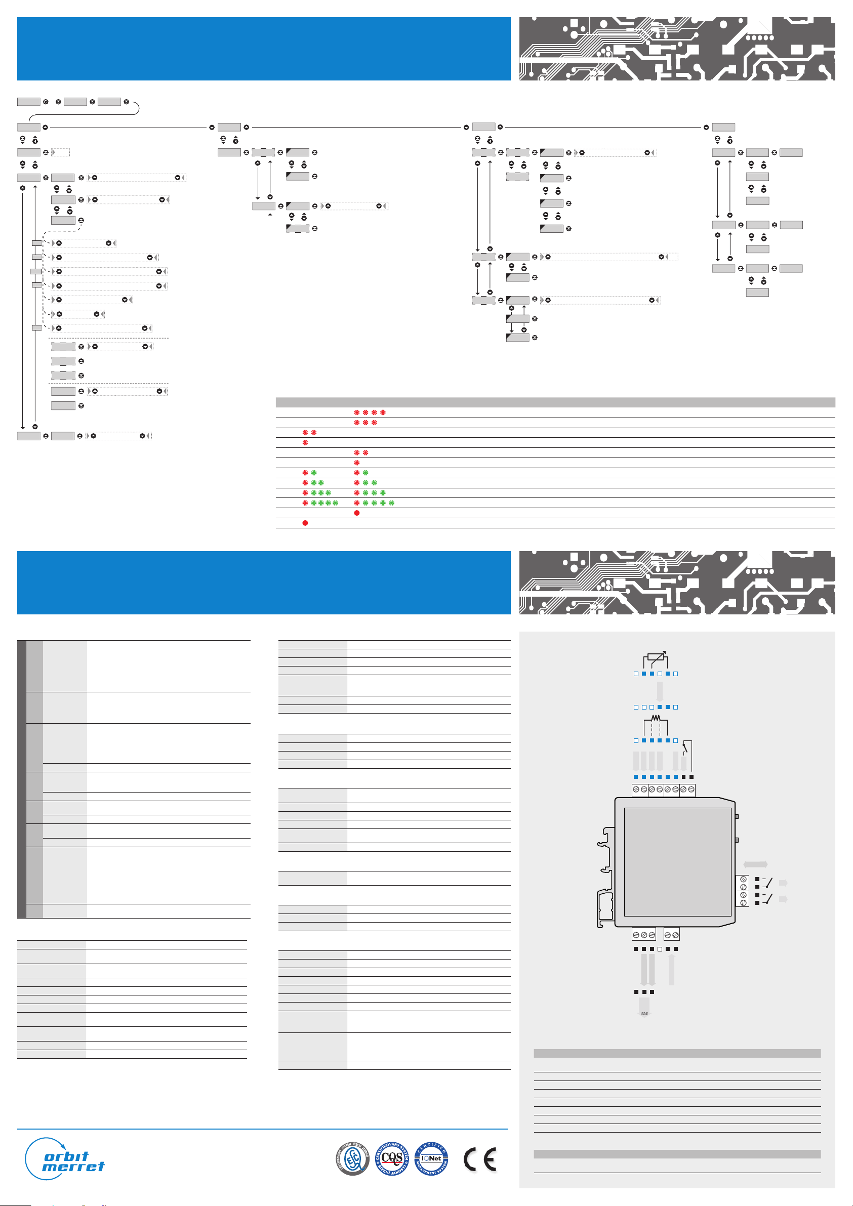
CONNECTION AND CONTROLLING OF INSTRUMENT / TECHNICAL DATA
MEASURING INPUT
±80 mA < 1 V Input 5
±180 mA < 2 V Input 5
±30 mV > 10 MΩ Input 4
DC Ranges
PM Ranges
Ranges
OHM
Connection 2-, 3- or 4-wire
Type
INPUT
RTD
Connection 2-, 3- or 4-wire
Type
Ni
Connection 2-, 3- or 4-wire
Type
Cu
Connection 2-, 3- or 4-wire
T/C Type
Supply of linear
DU
potentiometer
±60 mV > 10 MΩ Input 4
±1 V > 10 MΩ Input 4
±20 V 1 MΩ Input 1
±40 V 1 MΩ Input 1
±80 V 1 MΩ Input 1
±20 mA < 200 mV Input 5
4...20 mA < 200 mV Input 5
±2 V > 10 MΩ Input 1
±5 V 1 MΩ Input 1
±10 V 1 MΩ Input 1
0…100 Ω
0...300 Ω
0...1,5 kΩ
0...3 kΩ
0…24 kΩ
0...30 kΩ (only for 2- or 4-wire)
EU > 100/500/1000 Ω, w.3 850 ppm -50°…450°C
US > 100 Ω, with 3 920 ppm/°C -50°…450°C
RU > 50/100 Ω with 3 910 ppm/°C -200°…1 100°/450°C
Ni 1000/ Ni 10000 w.5 000 ppm/°C -50°…250°C
Ni 1000/ Ni 10000 w.6 180 ppm/°C -200°…250°C
Cu 50/Cu 100 with 4 260 ppm/°C -50°…200°C
Cu 50/Cu 100 with 4 280 ppm/°C -200°…200°C
J (Fe-CuNi) -200°...900°C
K(NiCr-Ni) -200°...1 300°C
T (Cu-CuNi) -200°...400°C
E (NiCr-CuNi) -200°...690°C
B (PtRh30-PtRh6) 300°...1 820°C
S(PtRh10-Pt) -50°...1 760°C
R (Pt13Rh-Pt) -50°...1 740°C
N (Omegalloy) -200°...1 300°C
L (Fe-CuNi) -200°...900°C
2,5 VDC/6 mA, min. resistance of potentiometer is 500 Ω
INSTRUMENT’S ACCURACY
TK 50 ppm/°C
Accuracy
Accuracy of cold
junction measurement
Rate 0,5…80 measurements/s
Overload capacity 10x (t < 30 ms), 2x
Digital fi ltres exponencialn fi lter, rounding
Function Hold - “freezing the measured value”, Tare (upon contact)
External input
OM Link
Watch-dog reset after 500 ms
Calibration at 25° C and40 % r.h .
Instrument‘s power supply leads should not be in vicinity of low level input signals. Contactors, medium and high power electrical motors must not be used in vicinity of the instrument.
Input signal leads (measured value) need to be separated from all high power leads and devices. Instruments are tested in accordance with standards for industrial use, however we
strongly advise you to adhere to the above mentioned precaution measures.
±0,05 % of the range + 1 digit
±0,05 % of the range + 1 digit
±1,5°C
1, with the possibility of assigning various functions in
the instrument’s menu
Company communication interface for operating,
setting and updating of instruments
In order to ensure proper functionality of this instrument it is absolutely essential to connect the input leads shielding to the junction box‘ frame.
ORBIT MERRET, spol. s r. o.
Vodňanská 675/30, 198 00 Prague 9, Czech republic
tel.: +420 281 040 200, fax.: +420 281 040 299
e-mail: orbit@merret.eu, www.orbit.merret.eu
COMPARATOR
Type digital, setting in vmenu
Limits 0…999999
Hysteresis 0…999999
Delay 0…99,9 s
Outputs
Reaction speed < 50 ms
Relay 1/8 HP 277 VAC, 1/10 HP 125 V, Pilot Duty D300
* values apply to resistive load
up to 2x relays with switch-on contact (Form A),
(250 VAC/30 VDC, 3 A)*
2x open collector, (30 VDC/100 mA)*
DATA OUTPUT
Protocol ASCII
Data format 8 bit + no parity + 1 stop bit
Rate 600…230 400 Baud
RS 485 isolated, adressing (max. 31 instruments)
ANALOG OUTPUT
Type
Non-linearity 0,1 % of range
TK 15 ppm/°C
Rate response to change of value < 1 ms
Output
Ripple 5 mV residual ripple at output voltage of 10 V
isolated, programmable with 12-bit D/A converter,
type and range are selectable in menu
0…2/5/10 V, ±10 V, 0…5 mA, 0/4…20 mA
(comp. < 500 Ω/12 V), Detection of broken loop
POWER SUPPLY
10…30 VDC/24 VAC, ±10 %, 3 VA, PF ≥ 0,4,
I
< 40 A/1 ms, isolated
STP
MECHANIC PROPERTIES
Material PA 66, incombustible UL 94 V-0, blue
Dimensions 90,5 x 79 x 25 mm
Installation to DIN rail, wide 35 mm
OPERATING CONDITIONS
Connection connector terminal board, cross section < 1,5/2,5 mm
Stabilization period within 15 minutes after switch-on
Working temperature -20°…60°C
Storage temperature -20°…85°C
Cover IP20
Execution safety class I
El. safety EN 61010-1, A2
Dielectric strength
Insulation resistance*
EMC EN 61326-1 (Industrial environment)
* PI - Primary insulation, DI - Double insulation
2,5 kVAC after 1 min between supply/input
2,5 kVAC after 1 min between supply/outputs
4 kVAC after 1 min between input/relays output
for pollution degree II, measuring cat. III.
power supply > 300 V (PI), 255 V (DI)
input/output > 300 V (PI)
input/output - relay > 300 V (DI)
MINI-TECHDOK - OMX 333UNI - 2012 - 1v1 - en
2
+
-
INPUT 4
GND
+
-
ESE-
S-
S+ S-E+ E-
DU
T/C
ES+
ES+
RTD, OHM, Ni
INPUT 2
INPUT 1
INPUT 3
+-+
+
JKLMNONO
123 45
+
+
AO - current
AO - voltage
GND
-
+
Rx/Tx-
Termination
Rx/Tx+
485
EXT.1
INPUT 4
INPUT 5
GND
+
+
--
Power supply
DC, PM
OM Link
4
123
L1
L2
+
MEASURING RANGES - CONNECTION
TYPE INPUTS 1 INPUTS 2 INPUTS 3 INPUTS 4 INPUTS 5
DC ±20/±40/±80 V
PM ±2/±5/±10 V 0/4…20 mA
OHM 0…300 Ω/0…1,5 kΩ/0…3 kΩ/0…30 kΩ
RTD-PT Pt 100/Pt 500/Pt 1 000
RTD-CU Cu 50/Cu 100
RTD-NI Ni 1 000/Ni 10 000
T/C J/K/T/E/B/S/ R/N/L
DU Linear potentiometr (min. 500 Ω)
±30/60 mV
±1 V
±80/±180 mA
EXTERNAL INPUT
DESCRIPTION ACTION
EXT. 1
control input, functionality according to
setting in the menu (see Menu > EXT.1)
upon contact, terminal (no. N + O)
 Loading...