

Orbit Merret OMX 100, OMX 100DC, OMX 100PWR, OMX 100PM, OMX 100RTD Instructions Manual
...
GUARANTEE
YERS
OMX 100
PROGRAMMABLE TRANSMITTER
DC VOLTMETER/AMMETER
AC VOLTMETER/AMMETER
PROCESS MONITOR
THERMOMETER FOR PT 100/500/1 000
THERMOMETER FOR THERMOCOUPLES
DISPLAY INSTR.FOR LIN.POTENTIOMETERS
OHMMETER
THERMOMETER FOR NI 1 000
1

INSTRUCTIONS FOR USE OMX 100
SAFETY INSTRUCTIONS
Please, read the enclosed safety instructions carefully and observe them!
These instruments should be safeguarded by isolated or common fuses (breakers)!
For safety information the EN 61 010-1 + A2 standard must be observed.
This instrument is not explosion-safe!
TECHNICAL DATA
Transmitters of the OMX 100 series conform to European regulation 89/336/EWG and the Ordinance 168/1997
Coll.
They are up to the following European standards:
EN 55 022, class B
EN 61000-4-2, -4, -5, -6, -8, -9, -10, -11
The instruments are applicable for unlimited use in agricultural and industrial areas.
CONNECTION
Supply of energy from the main line has to be isolated from the measuring leads.
ORBIT MERRET, spol. s r.o.
Vodnanská 675/30
198 00 Prague 9
Czech Republic
Tel: +420 - 281 040 200
Fax: +420 - 281 040 299
e-mail: orbit@merret.cz
www.orbit.merret.cz
2

1. CONTENTS
1. CONTENTS
1. Contents . . . . . . . . . . . . . . . . . . . . . . . . . . . . . . . . . . . . . . . . . . . . . . . . . . . . . . . . . . . . . . . . . . . . . . . . . . . . . . . . . . . . . . . . . 3
2. Instrument description . . . . . . . . . . . . . . . . . . . . . . . . . . . . . . . . . . . . . . . . . . . . . . . . . . . . . . . . . . . . . . . . . . . . . . . . . . . . . . 4
3. Connection . . . . . . . . . . . . . . . . . . . . . . . . . . . . . . . . . . . . . . . . . . . . . . . . . . . . . . . . . . . . . . . . . . . . . . . . . . . . . . . . . . . . . . . 6
4. Instrument setting . . . . . . . . . . . . . . . . . . . . . . . . . . . . . . . . . . . . . . . . . . . . . . . . . . . . . . . . . . . . . . . . . . . . . . . . . . . . . . . . . . 8
Setting the DP and the (-) sign . . . . . . . . . . . . . . . . . . . . . . . . . . . . . . . . . . . . . . . . . . . . . . . . . . . . . . . . . . . . . . . . . . . . . . . . . . . . . . 9
Access into Configuration menu . . . . . . . . . . . . . . . . . . . . . . . . . . . . . . . . . . . . . . . . . . . . . . . . . . . . . . . . . . . . . . . . . . . . . . . . . . . . 9
4.1 Guide through minimum instrument setting . . . . . . . . . . . . . . . . . . . . . . . . . . . . . . . . . . . . . . . . . . . . . . . . . . . . . . . . . . . 10
4.2 Configuration menu . . . . . . . . . . . . . . . . . . . . . . . . . . . . . . . . . . . . . . . . . . . . . . . . . . . . . . . . . . . . . . . . . . . . . . . . . . . . . 12
4.2.1 Configuration mode - INPUT . . . . . . . . . . . . . . . . . . . . . . . . . . . . . . . . . . . . . . . . . . . . . . . . . . . . . . . . . . . . . . . . 13
4.2.1.1 Internal values resetting . . . . . . . . . . . . . . . . . . . . . . . . . . . . . . . . . . . . . . . . . . . . . . . . . . . . . . . . . . . . 13
4.2.1.2 Counter resetting . . . . . . . . . . . . . . . . . . . . . . . .
4.2.1.3.1 Setting the measuring range . . . . . . . . . . . . . . . . . . . . . . . . . . . . . . . . . . . . . . . . . . . . . . . . . . . . . . . . 14
4.2.1.3.2 Shifting the beginning of the range . . . . . . . . . .
4.2.1.3.3 Compensation of 2-wire conduct . . . . . . . . . . .
4.2.1.3.4 Setting the mode of assessment of CJC
4.2.1.3.5 Setting the temperature of CJC . . . . . . . . . . . . .
4.2.1.3.6 Setting the time base . . . . . . . . . . . . . . . . . . . . .
4.2.1.3.7 Setting the input filter parameters . . . . . . . . . . .
4.2.1.3.8 Setting the display status backup . . . . . . . . . . . F . . . . . . . . . . . . . . . . . . . . . . . . . . . . . . . . . . . 17
4.2.1.3.9 Setting the instrument measuring rate . . . . . . . . . . . . . . . . . . . . . . . . . . . . . . . . . . . . . . . . . . . . . . . . . 17
4.2.1.3.10 Selection of auto. menu presetting . . . . . . . . .
4.2.1.4 Selection of external input function . . . . . . . . . . . . . . . . . . . . . . . . . . . . . . . . . . . . . . . . . . . . . . . . . . . 18
4.2.1.5 Setting another function of the control key „enter“ . . . . . . . . . . . . . . . . . . . . . . . . . . . . . . . . . . . . . . . 18
4.2.2 Configuration mode - CHANNELS . . . . . . . . . . . . . . . . . . . . . . . . . . . . . . . . . . . . . . . . . . . . . . . . . . . . . . . . . . . 20
4.2.2.1 Display projection . . . . . . . . . . . . . . . . . . . . . . .
4.2.2.2 Setting the digital filters . . . . . . . . . . . . . . . . . . . . . . . . . . . . . . . . . . . . . . . . . . . . . . . . . . . . . . . . . . . . 21
4.2.2.3 Setting the decimal point . . . . . . . . . . . . . . . . . .
4.2.2.4 Setting the measuring units description . . . . . . . DC PM DU
4.2.3 Configuration mode - OUTPUTS . . . . . . . . . . . . . . . . . . . . . . . . . . . . . . . . . . . . . . . . . . . . . . . . . . . . . . . . . . . . . 24
4.2.3.1.1 Limits - type of relay switching . . . . . . . . . . . . . . . . . . . . . . . . . . . . . . . . . . . . . . . . . . . . . . . . . . . . . 24
4.2.3.1.2 Limits - setting the bounds . . . . . . . . . . . . . . . . . . . . . . . . . . . . . . . . . . . . . . . . . . . . . . . . . . . . . . . . 24
4.2.3.2.1 Data output - rate . . . . . . . . . . . . . . . . . . . . . . . . . . . . . . . . . . . . . . . . . . . . . . . . . . . . . . . . . . . . . . . 25
4.2.3.2.2 Data output -address . . . . . . . . . . . . . . . . . . . . . . . . . . . . . . . . . . . . . . . . . . . . . . . . . . . . . . . . . . . . 25
4.2.3.3.1 Analog output - type . . . . . . . . . . . . . . . . . . . . . . . . . . . . . . . . . . . . . . . . . . . . . . . . . . . . . . . . . . . . 25
4.2.3.3.2 Analog output - range . . . . . . . . . . . . . . . . . . . . . . . . . . . . . . . . . . . . . . . . . . . . . . . . . . . . . . . . . . . 26
4.2.3.4 Display projection . . . . . . . . . . . . . . . . . . . . . . . . . . . . . . . . . . . . . . . . . . . . . . . . . . . . . . . . . . . . . . 26
4.2.4 Configuration mode - SERVICE . . . . . . . . . . . . . . . . . . . . . . . . . . . . . . . . . . . . . . . . . . . . . . . . . . . . . . . . . . . . . . 28
4.2.4.1 Restoration of manufacture setting . . . . . . . . . . . . . . . . . . . . . . . . . . . . . . . . . . . . . . . . . . . . . . . . . 28
4.2.4.2 Input range calibration . . . . . . . . . . . . . . . . . . . . . . DU . . . . . . . . . . . . . . . . . . . . . . . . . . . . . . . 29
4.2.4.3 Setting new access password . . . . . . . . . . . . . . . . . . . . . . . . . . . . . . . . . . . . . . . . . . . . . . . . . . . . . 29
5. Table of symbols . . . . . . . . . . . . . . . . . . . . . . . . . . . . . . . . . . . . . . . . . . . . . . . . . . . . . . . . . . . . . . . . . . . . . . . . . . . . . . . . . 30
6. Method of measuring of CJC . . . . . . . . . . . . . . . . . . . . . . . . . . . . . . . . . . . . . . . . . . . . . . . . . . . . . . . . . . . . . . . . . . . . . . . 31
7. Data protocol . . . . . . . . . . . . . . . . . . . . . . . . . . . . . . . . . . . . . . . . . . . . . . . . . . . . . . . . . . . . . . . . . . . . . . . . . . . . . . . . . . . . 32
8. Error statements . . . . . . . . . . . . . . . . . . . . . . . . . . . . . . . . . . . . . . . . . . . . . . . . . . . . . . . . . . . . . . . . . . . . . . . . . . . . . . . . . . 33
9. Technical data . . . . . . . . . . . . . . . . . . . . . . . . . . . . . . . . . . . . . . . . . . . . . . . . . . . . . . . . . . . . . . . . . . . . . . . . . . . . . . . . . . . . 36
10. Instrument dimensions and installation . . . . . . . . . . . . . . . . . . . . . . . . . . . . . . . . . . . . . . . . . . . . . . . . . . . . . . . . . . . . . . . 38
11. Certificate of guarantee . . . . . . . . . . . . . . . . . . . . . . . . . . . . . . . . . . . . . . . . . . . . . . . . . . . . . . . . . . . . . . . . . . . . . . . . . . . 39
Declaration of conformity . . . . . . . . . . . . . . . . . . . . . . . . . . . . . . . . . . . . . . . . . . . . . . . . . . . . . . . . . . . . . . . . . . . . . . . . . . 40
4.2.4.4 Instrument identification . . . . . . . . . . . . . . . . . . . . . . . . . . . . . . . . . . . . . . . . . . . . . . . . . . . . . . . . . . 29
F
. . . . . . . . . . . . . . . . . . . . . . . . . . . . . . . . . . . 13
T/C
RTD OHM
RTD OHM
. 15
T/C
. . . . . . . . . . . . . . . . . . . . . . . . . . . . . 15
. . . . . . . . . . . . . . . . . . . . . . . . . . . . . 15
. . . . . . . . . . . . . . . . . . . . . . . . . . . . . . . . . . . . 16
F
. . . . . . . . . . . . . . . . . . . . . . . . . . . . . . . . . . . 16
F
. . . . . . . . . . . . . . . . . . . . . . . . . . . . . . . . . . . 16
DC PM
OHM
F . . . . . . . . . . . . . . . . . . 18
DC PM
DC PM
DU
DU
OHM
OHM
OHM
F . . . . . . . . . . . . . 20
F . . . . . . . . . . . . . 21
F . . . . . . . . . . . . 22
3

INSTRUCTIONS FOR USE OMX 100
2. INSTRUMENT DESCRIPTION
DESCRIPTION
The OMX 100 model series are programmable transmitters to DIN rail manufactured in the following types:
OMX 100DC DC voltmeter/ammeter
OMX 100PWR AC voltmeter/ammeter, wattmetr
OMX 100PM Process monitor
OMX 100RTD Thermometer for Pt 100/500/1 000, Ni 1 000
OMX 100T/C Thermometer for thermocouples
OMX 100DU Display instrument for linear potentiometers
OMX 100OHM Ohmmeter
OMX 100F Frequency meter
The instruments are based on an 8-bit microcontroller with A/D converter, that secures high accuracy, stability and
easy operation of the instrument.
Programmable projection of the display
Calibration projection for the beginning and the end of the input range
setting the input type
Projection -99…999
Digital filters
Exponen. average from 2…100 measurements
Rounding setting the projection step for display
Mathematic functions
Tare* assigned to reset display in case of non-zero input signal
External control
Hold display/instrument blocking
Lock locking the control keys for access into Configuration menu
Tare tare activation
Resetting counter resetting/preset
Output
Analog programmable
0…5 mA, 0…20 mA, 4…20 mA (with error statement evaluation 3 mA)
0…2/5/10 V
0,2…2 200 Hz
4
* only for type DC, PM, DU

2. INSTRUMENT DESCRIPTION
OPERATION
The transmitter is set by two control keys on the front panel or via data line RS 232/485.
A standard equipment is the OM Link interface, through which it is possible to modify and store all settings. The
OM Link program is freely procurable, to be downloaded from the web site. For the connection an OM Link cable
is necessary.
All programmable parameters are stored in the EEPROM memory (they hold even after the instrument is switched
off).
EXTENSION
Excitation is suitable for feeding sensors and converters. It has a galvanic isolation of 12…24 VDC.
Comparators are assigned to control two limit values with relay output. The limits have adjustbale hysteresis as
well as selectable delay of the switch-on. Reaching the preset limits is signalled by LED and simultaneously by the
switch-on of the relevant relay.
Data outputs are for their rate and accuracy suitable for transmission of the measured data for further projection or
directly into the control systems. We offer an isolated RS 232 and RS 485 with the ASCII protocol.
Real time is an internal time control of data collection. It is suitable everywhere where it is neccessary to register
measured values in a given time segment. Up to 65 000 values may be stored in the instrument‘s memory. Data
transmission into PC via serial interface RS232/485
FIRMWARE www.orbit.merret.cz/update
With respect to the continuous development and innovation of our products it is now possible to download the most
recent program version for every instrument directly from the web pages.
After connecting the instrument to PC and running the program the upgrade is performed automatically .
Number of the current program version in your instrument can be found in „Configuration menu - service - identifi-
cation“
5
INSTRUCTIONS FOR USE OMX 100
3. CONNECTION
The lead for feeding the instrument should not be in the proximity of the incoming low-potential signals.
Contactors, motors with larger input power and other efficient elements should not be in the proximity of the instru-
ment.
The lead into the input of the instrument (the measured quantity) should be in sufficient distance from all power leads
and appliances. Provided this cannot be secured it is necessary to use shielded leads with connection to ground.
The instruments are tested in compliance with standards for use in industrial area, yet we recommend to abide by
the above mentioned principles.
MEASURING RANGES
Type Input 1 Input 2 Input 3
OMX 100 PWR
OMX 100 PWR
OMX 100 DC
OMX 100 DC
OMX 100 PM
OMX 100 OHM
OMX 100 F
Input 1 > 0…60 mV * 0…150 mV * 0…300 mV * 0…1 A * 0…5 A
Input 2 > 0…10 V * 0…100 V * 0…150 V * 0…250 V * 0…450 V
±4/±40 mA ±0,4/±4 V ±40/±400 V
0…1/5 A 0…60/150 mV
0/4…20 mA 0…2 V 0…5/10 V
0…999 Ohm * 0...9,99 kOhm * 0...99,9 kOhm * 5…105 Ohm
< 30 V < 150 V < 300 V
Grounding on terminal „E“ has to be connected at
all times.
Feeding of an open collector (OC) for
frequency output max. 40 V, (internal
resistance 5k6)
Relay parameters listed in Technical data apply for resistance
load. Upon connection of induction load we recommend
fitting the leads to relay 1 A with a fuse for protection of
maximum load.
In RTD and OHM inputs it is necessar y in 2 or 3-wire connec-
tion to link the unconnected inputs to terminal board.
6
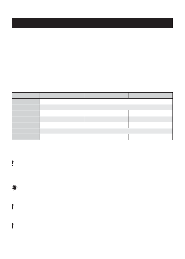
3. INSTRUMENT CONNECTION
232
485
POWER
LNE
-
+
AO - supply OC
+
+
L1
AO - frequency
-
OMX 100DC, PM, F
INPUT 2
INPUT 1
GND
-
INPUT 3
+
+
+
AO - voltage
+
Hold/Lock
AO - current
+
-
OMX 100DU
E
B
OMX 100PWR
INPUT I
INPUT U
GND
OMX 100RTD
ES-
ES+
S-
ES+
E-
S+
E-
S-
E+
OM Link
GND GND
RxD Rx/Tx+
TxD
L2
232
Rx/Tx-
485
+
Exc.
-
OMX 100T/C
INPUT
GND-CJC
+
7
INSTRUCTIONS FOR USE OMX 100
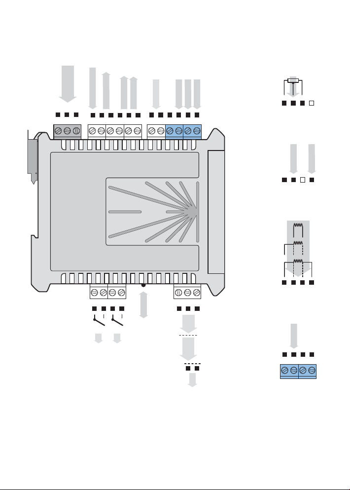
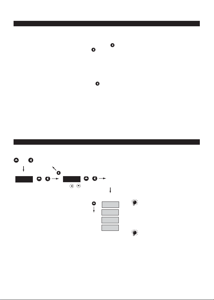
4. INSTRUMENT SETTING
The instrument is set and controlled by 5 control keys located on the front panel. By means of these controls it is
possible to browse through the operating program and to select and set the required values.
Input value
+ 3 digit optional
projection of meas.unit
Relay status - red LED
ON number is alight
OFF number is not alight
OFF number is flashing
limits w/restriction
(hysteresis, delay)
Signalization - green LED
ON LED is alight
ON LED is flashing
error statement
OFF LED is not alight
SYMBOLS USED IN THE INSTRUCTIONS
DC AC PM DU OHM RTD T/C
INPUT
OUTPUT
12
Output value
+ 3 digit optional
projection of meas.unit
Control keys
Indicates the setting for given type of instrument
CONTROL KEYS FUNCTIONS
+
Measuring mode
UP* LEFT* UP + LEFT
tare/resetting tare projection access into menu
Moving around in the menu
move to next item return to previous level confirm selected item
Setting/selection - items
move up move down confirm selected item
Setting - numbers
change of current figure - up - move to higher decade confirm selected number
* control keys react after being released
8
4. INSTRUMENT SETTING
SETTING THE DECIMAL POINT AND THE (-) SIGN
DECIMAL POINT
Its selection in the setting mode is performed by control key with transition behind the highest decade, when the
data starts flashing. Positioning is performed by
For projection of value exceeding 999 the „k“ suffix may be set up (display value is multiplied by 1000, only for
frequency output).
MINUS SIGN
Setting the minus sign is performed by control key on the higher decade. When editing the item, figures change
in numeric row 0,1…9,-,0,1
ACCESS INTO THE CONFIGURATION MODE
.
+
PAS
w/o saving
+
000
shift left
+
9,8,7…
OK
CHA .
INP .
The code from manufacture is always
preset to 000. In case of loss of access
password it is possible to use the universal access
code "177"
OUT.
SER.
If the code is preset to 000 the access
into the menu is free, i.e. without call for
its setting
9
INSTRUCTIONS FOR USE OMX 100
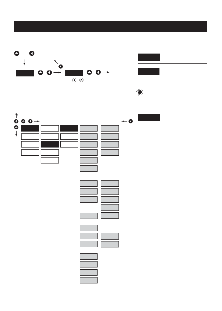
4.1 GUIDE THROUGH MINIMUM INSTRUMENT SETTING
Access into the „Configuration menu““
+
PAS
Selection of the measuring range/input type
+
INP.
CHA .
OUT.
SER.
w/o saving
+
CL. T.
CL. C.
CFG
AUX.
KEY
000
shift left
MOD
M.P.S.
CH.S.
+
9,8,7…
DC - 1
U 0.4
U 4
U 40
400
I 4
I 40
RTD
2-W
3-W
4-W
T/C
OK
DC - 2
60 m
150
I 1
I 5
PM
U 2
U 5
U 10
I 0
I 4
B
R
S
T
E
J
K
N
F
FRE .
COU .
password
its setting
DC Input
- setting the input range is dependant on the
ordered measuring range
PM Input
- setting the input range
RTD Input
- setting the type of connection
- in 2 or 3-wire connection it is necessary to link
the unconnected inputs (see the connection)
T/C Input
- setting the type of thermocouple is dependant
on the ordered measuring range
- B type B Range 1
R type R Range 2
S type S
T type T
E type E Range 3
J type J
K type K
N type N
Input F
- setting the measuring mode
- FRE. Frequency measurement
COU. Impulse counter
Entering the introductory
PAS
access password
Standard manufacture
000
setting of the access
If the code is preset to 000 the access
into „CM“ is free, i.e. without call for
Setting the instrument
MOD
measuring range
10

Setting the display projection
+
C. A.
A. O.
SET
FIL.
FOR .
DES .
TYP
MIN
MAX
MIN
MAX
I 5
I 4
E 4
I 20
U 2
U1 0
FRE .
OFF
INP.
CHA .
OUT.
SER.
Setting the analog output type - U/I
+
INP .
CHA .
OUT.
SER.
LIM
DAT .
DI S .
4. GUIDE THROUGH MINIMUM INSTRUMENT SETTING
Setting the display
MIN .
projection for minimum value
of the input signal
- range of the setting is -99…999
value of the input signal
- range of the setting is -99…999
DEF
Setting the display
MAX
projection for maximum
For type „F“ the items „SCA“ and „OFF“
will be displayed
Type - 0…5 mA
I 5
Type - 4…20 mA
I 4
Type - 4…20 mA with error
E 4
statement (3,0 mA)
Type - 0…20 mA
I 20
Type - 0…2 V
U 2
Type - 0…10 V
U1 0
Type - 0,2…2 200 Hz
FRE .
The output is off
OFF
Setting the analog output range - frequency
+
INP .
CHA .
OUT.
SER.
LIM
DAT .
DI S . MIN
A. O.
TYP
F. MI
F. MA
MAX
Setting the beginning of the
F. MI
frequency range for item
„MIN“
- range of the setting is 0,2…2 200 Hz
„MAX“
- range of the setting is 0,2…2 200 Hz
range
- range of the setting is -99…999
- range of the setting is -99…999
Setting the end of the
F. MA
frequency range for item
Assigning the display value
MIN
to the beginning of the AO
Assigning the display value
MAX
to the end of the AO range
11
INSTRUCTIONS FOR USE OMX 100
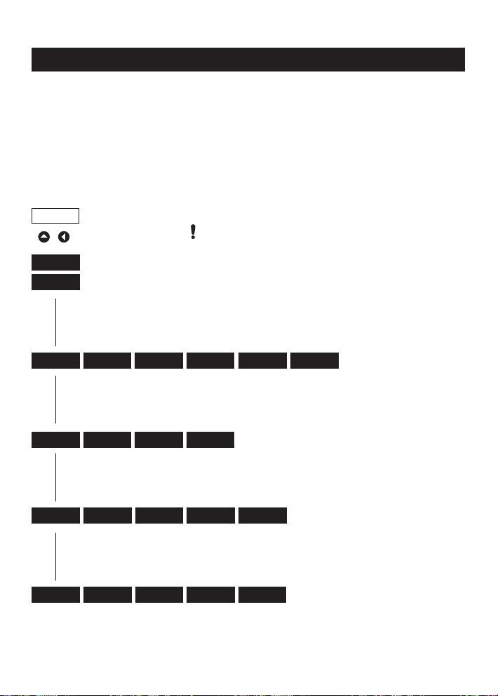
4.2 CONFIGURATION MENU
• designated for professional service and maintenance
• complete instrument setting
• access is protected by password or a shorting link on the input connector
23 .6
+
Upon delay longer than 30 s the programming mode is automatically discontinued and the instrument itself switches back to measuring mode
PAS
000
INP .
CHA .
CL. T. CFG .
Resetting internal values
SET FOR .
Setting
projection for
min/max input
signal
Entering the access password
CL. C
Counter
resetting
Auxiliary input
function
FIL.
Setting the
digital filters
Setting the
decimal point
OUT. LIM . DA T. A. O .
Setting
the limits,
hysteresis and
delay
Setting the
data output
Setting the
analog output
SER. RES. CA L N. PA.
Restoring
manufacture
setting/calibration
Instrument
calibration
Setting
new access
password
AUX.
Auxiliary input
function
DI S .
Mode of
display
projection
ID. .
Instrument
identification
KEY
Control key
function
Instrument setting
INP .
CHA
Instrument setting, calibration
OUT.
Setting the outputs
SER.
Service functions, authorization,
calibration
12
 Loading...