

GUARANTEE
YERS
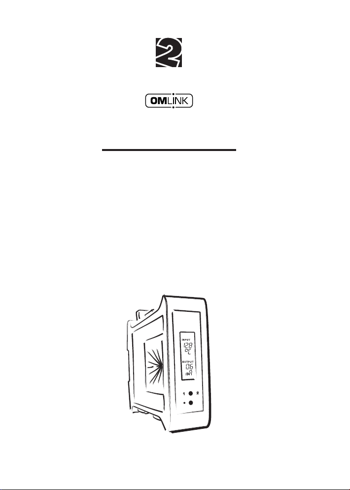
OMX 100
PROGRAMMABLE TRANSMITTER
DC VOLTMETER/AMMETER
AC VOLTMETER/AMMETER
PROCESS MONITOR
THERMOMETER FOR PT 100/500/1 000
THERMOMETER FOR THERMOCOUPLES
DISPLAY INSTR.FOR LIN.POTENTIOMETERS
OHMMETER
THERMOMETER FOR NI 1 000
1

INSTRUCTIONS FOR USE OMX 100
SAFETY INSTRUCTIONS
Please, read the enclosed safety instructions carefully and observe them!
These instruments should be safeguarded by isolated or common fuses (breakers)!
For safety information the EN 61 010-1 + A2 standard must be observed.
This instrument is not explosion-safe!
TECHNICAL DATA
Transmitters of the OMX 100 series conform to European regulation 89/336/EWG and the Ordinance 168/1997
Coll.
They are up to the following European standards:
EN 55 022, class B
EN 61000-4-2, -4, -5, -6, -8, -9, -10, -11
The instruments are applicable for unlimited use in agricultural and industrial areas.
CONNECTION
Supply of energy from the main line has to be isolated from the measuring leads.
ORBIT MERRET, spol. s r.o.
Vodnanská 675/30
198 00 Prague 9
Czech Republic
Tel: +420 - 281 040 200
Fax: +420 - 281 040 299
e-mail: orbit@merret.cz
www.orbit.merret.cz
2
1. CONTENTS
1. CONTENTS
1. Contents . . . . . . . . . . . . . . . . . . . . . . . . . . . . . . . . . . . . . . . . . . . . . . . . . . . . . . . . . . . . . . . . . . . . . . . . . . . . . . . . . . . . . . . . . 3
2. Instrument description . . . . . . . . . . . . . . . . . . . . . . . . . . . . . . . . . . . . . . . . . . . . . . . . . . . . . . . . . . . . . . . . . . . . . . . . . . . . . . 4
3. Connection . . . . . . . . . . . . . . . . . . . . . . . . . . . . . . . . . . . . . . . . . . . . . . . . . . . . . . . . . . . . . . . . . . . . . . . . . . . . . . . . . . . . . . . 6
4. Instrument setting . . . . . . . . . . . . . . . . . . . . . . . . . . . . . . . . . . . . . . . . . . . . . . . . . . . . . . . . . . . . . . . . . . . . . . . . . . . . . . . . . . 8
Setting the DP and the (-) sign . . . . . . . . . . . . . . . . . . . . . . . . . . . . . . . . . . . . . . . . . . . . . . . . . . . . . . . . . . . . . . . . . . . . . . . . . . . . . . 9
Access into Configuration menu . . . . . . . . . . . . . . . . . . . . . . . . . . . . . . . . . . . . . . . . . . . . . . . . . . . . . . . . . . . . . . . . . . . . . . . . . . . . 9
4.1 Guide through minimum instrument setting . . . . . . . . . . . . . . . . . . . . . . . . . . . . . . . . . . . . . . . . . . . . . . . . . . . . . . . . . . . 10
4.2 Configuration menu . . . . . . . . . . . . . . . . . . . . . . . . . . . . . . . . . . . . . . . . . . . . . . . . . . . . . . . . . . . . . . . . . . . . . . . . . . . . . 12
4.2.1 Configuration mode - INPUT . . . . . . . . . . . . . . . . . . . . . . . . . . . . . . . . . . . . . . . . . . . . . . . . . . . . . . . . . . . . . . . . 13
4.2.1.1 Internal values resetting . . . . . . . . . . . . . . . . . . . . . . . . . . . . . . . . . . . . . . . . . . . . . . . . . . . . . . . . . . . . 13
4.2.1.2 Counter resetting . . . . . . . . . . . . . . . . . . . . . . . .
4.2.1.3.1 Setting the measuring range . . . . . . . . . . . . . . . . . . . . . . . . . . . . . . . . . . . . . . . . . . . . . . . . . . . . . . . . 14
4.2.1.3.2 Shifting the beginning of the range . . . . . . . . . .
4.2.1.3.3 Compensation of 2-wire conduct . . . . . . . . . . .
4.2.1.3.4 Setting the mode of assessment of CJC
4.2.1.3.5 Setting the temperature of CJC . . . . . . . . . . . . .
4.2.1.3.6 Setting the time base . . . . . . . . . . . . . . . . . . . . .
4.2.1.3.7 Setting the input filter parameters . . . . . . . . . . .
4.2.1.3.8 Setting the display status backup . . . . . . . . . . . F . . . . . . . . . . . . . . . . . . . . . . . . . . . . . . . . . . . 17
4.2.1.3.9 Setting the instrument measuring rate . . . . . . . . . . . . . . . . . . . . . . . . . . . . . . . . . . . . . . . . . . . . . . . . . 17
4.2.1.3.10 Selection of auto. menu presetting . . . . . . . . .
4.2.1.4 Selection of external input function . . . . . . . . . . . . . . . . . . . . . . . . . . . . . . . . . . . . . . . . . . . . . . . . . . . 18
4.2.1.5 Setting another function of the control key „enter“ . . . . . . . . . . . . . . . . . . . . . . . . . . . . . . . . . . . . . . . 18
4.2.2 Configuration mode - CHANNELS . . . . . . . . . . . . . . . . . . . . . . . . . . . . . . . . . . . . . . . . . . . . . . . . . . . . . . . . . . . 20
4.2.2.1 Display projection . . . . . . . . . . . . . . . . . . . . . . .
4.2.2.2 Setting the digital filters . . . . . . . . . . . . . . . . . . . . . . . . . . . . . . . . . . . . . . . . . . . . . . . . . . . . . . . . . . . . 21
4.2.2.3 Setting the decimal point . . . . . . . . . . . . . . . . . .
4.2.2.4 Setting the measuring units description . . . . . . . DC PM DU
4.2.3 Configuration mode - OUTPUTS . . . . . . . . . . . . . . . . . . . . . . . . . . . . . . . . . . . . . . . . . . . . . . . . . . . . . . . . . . . . . 24
4.2.3.1.1 Limits - type of relay switching . . . . . . . . . . . . . . . . . . . . . . . . . . . . . . . . . . . . . . . . . . . . . . . . . . . . . 24
4.2.3.1.2 Limits - setting the bounds . . . . . . . . . . . . . . . . . . . . . . . . . . . . . . . . . . . . . . . . . . . . . . . . . . . . . . . . 24
4.2.3.2.1 Data output - rate . . . . . . . . . . . . . . . . . . . . . . . . . . . . . . . . . . . . . . . . . . . . . . . . . . . . . . . . . . . . . . . 25
4.2.3.2.2 Data output -address . . . . . . . . . . . . . . . . . . . . . . . . . . . . . . . . . . . . . . . . . . . . . . . . . . . . . . . . . . . . 25
4.2.3.3.1 Analog output - type . . . . . . . . . . . . . . . . . . . . . . . . . . . . . . . . . . . . . . . . . . . . . . . . . . . . . . . . . . . . 25
4.2.3.3.2 Analog output - range . . . . . . . . . . . . . . . . . . . . . . . . . . . . . . . . . . . . . . . . . . . . . . . . . . . . . . . . . . . 26
4.2.3.4 Display projection . . . . . . . . . . . . . . . . . . . . . . . . . . . . . . . . . . . . . . . . . . . . . . . . . . . . . . . . . . . . . . 26
4.2.4 Configuration mode - SERVICE . . . . . . . . . . . . . . . . . . . . . . . . . . . . . . . . . . . . . . . . . . . . . . . . . . . . . . . . . . . . . . 28
4.2.4.1 Restoration of manufacture setting . . . . . . . . . . . . . . . . . . . . . . . . . . . . . . . . . . . . . . . . . . . . . . . . . 28
4.2.4.2 Input range calibration . . . . . . . . . . . . . . . . . . . . . . DU . . . . . . . . . . . . . . . . . . . . . . . . . . . . . . . 29
4.2.4.3 Setting new access password . . . . . . . . . . . . . . . . . . . . . . . . . . . . . . . . . . . . . . . . . . . . . . . . . . . . . 29
5. Table of symbols . . . . . . . . . . . . . . . . . . . . . . . . . . . . . . . . . . . . . . . . . . . . . . . . . . . . . . . . . . . . . . . . . . . . . . . . . . . . . . . . . 30
6. Method of measuring of CJC . . . . . . . . . . . . . . . . . . . . . . . . . . . . . . . . . . . . . . . . . . . . . . . . . . . . . . . . . . . . . . . . . . . . . . . 31
7. Data protocol . . . . . . . . . . . . . . . . . . . . . . . . . . . . . . . . . . . . . . . . . . . . . . . . . . . . . . . . . . . . . . . . . . . . . . . . . . . . . . . . . . . . 32
8. Error statements . . . . . . . . . . . . . . . . . . . . . . . . . . . . . . . . . . . . . . . . . . . . . . . . . . . . . . . . . . . . . . . . . . . . . . . . . . . . . . . . . . 33
9. Technical data . . . . . . . . . . . . . . . . . . . . . . . . . . . . . . . . . . . . . . . . . . . . . . . . . . . . . . . . . . . . . . . . . . . . . . . . . . . . . . . . . . . . 36
10. Instrument dimensions and installation . . . . . . . . . . . . . . . . . . . . . . . . . . . . . . . . . . . . . . . . . . . . . . . . . . . . . . . . . . . . . . . 38
11. Certificate of guarantee . . . . . . . . . . . . . . . . . . . . . . . . . . . . . . . . . . . . . . . . . . . . . . . . . . . . . . . . . . . . . . . . . . . . . . . . . . . 39
Declaration of conformity . . . . . . . . . . . . . . . . . . . . . . . . . . . . . . . . . . . . . . . . . . . . . . . . . . . . . . . . . . . . . . . . . . . . . . . . . . 40
4.2.4.4 Instrument identification . . . . . . . . . . . . . . . . . . . . . . . . . . . . . . . . . . . . . . . . . . . . . . . . . . . . . . . . . . 29
F
. . . . . . . . . . . . . . . . . . . . . . . . . . . . . . . . . . . 13
T/C
RTD OHM
RTD OHM
. 15
T/C
. . . . . . . . . . . . . . . . . . . . . . . . . . . . . 15
. . . . . . . . . . . . . . . . . . . . . . . . . . . . . 15
. . . . . . . . . . . . . . . . . . . . . . . . . . . . . . . . . . . . 16
F
. . . . . . . . . . . . . . . . . . . . . . . . . . . . . . . . . . . 16
F
. . . . . . . . . . . . . . . . . . . . . . . . . . . . . . . . . . . 16
DC PM
OHM
F . . . . . . . . . . . . . . . . . . 18
DC PM
DC PM
DU
DU
OHM
OHM
OHM
F . . . . . . . . . . . . . 20
F . . . . . . . . . . . . . 21
F . . . . . . . . . . . . 22
3

INSTRUCTIONS FOR USE OMX 100
2. INSTRUMENT DESCRIPTION
DESCRIPTION
The OMX 100 model series are programmable transmitters to DIN rail manufactured in the following types:
OMX 100DC DC voltmeter/ammeter
OMX 100PWR AC voltmeter/ammeter, wattmetr
OMX 100PM Process monitor
OMX 100RTD Thermometer for Pt 100/500/1 000, Ni 1 000
OMX 100T/C Thermometer for thermocouples
OMX 100DU Display instrument for linear potentiometers
OMX 100OHM Ohmmeter
OMX 100F Frequency meter
The instruments are based on an 8-bit microcontroller with A/D converter, that secures high accuracy, stability and
easy operation of the instrument.
Programmable projection of the display
Calibration projection for the beginning and the end of the input range
setting the input type
Projection -99…999
Digital filters
Exponen. average from 2…100 measurements
Rounding setting the projection step for display
Mathematic functions
Tare* assigned to reset display in case of non-zero input signal
External control
Hold display/instrument blocking
Lock locking the control keys for access into Configuration menu
Tare tare activation
Resetting counter resetting/preset
Output
Analog programmable
0…5 mA, 0…20 mA, 4…20 mA (with error statement evaluation 3 mA)
0…2/5/10 V
0,2…2 200 Hz
4
* only for type DC, PM, DU

2. INSTRUMENT DESCRIPTION
OPERATION
The transmitter is set by two control keys on the front panel or via data line RS 232/485.
A standard equipment is the OM Link interface, through which it is possible to modify and store all settings. The
OM Link program is freely procurable, to be downloaded from the web site. For the connection an OM Link cable
is necessary.
All programmable parameters are stored in the EEPROM memory (they hold even after the instrument is switched
off).
EXTENSION
Excitation is suitable for feeding sensors and converters. It has a galvanic isolation of 12…24 VDC.
Comparators are assigned to control two limit values with relay output. The limits have adjustbale hysteresis as
well as selectable delay of the switch-on. Reaching the preset limits is signalled by LED and simultaneously by the
switch-on of the relevant relay.
Data outputs are for their rate and accuracy suitable for transmission of the measured data for further projection or
directly into the control systems. We offer an isolated RS 232 and RS 485 with the ASCII protocol.
Real time is an internal time control of data collection. It is suitable everywhere where it is neccessary to register
measured values in a given time segment. Up to 65 000 values may be stored in the instrument‘s memory. Data
transmission into PC via serial interface RS232/485
FIRMWARE www.orbit.merret.cz/update
With respect to the continuous development and innovation of our products it is now possible to download the most
recent program version for every instrument directly from the web pages.
After connecting the instrument to PC and running the program the upgrade is performed automatically .
Number of the current program version in your instrument can be found in „Configuration menu - service - identifi-
cation“
5
INSTRUCTIONS FOR USE OMX 100
3. CONNECTION
The lead for feeding the instrument should not be in the proximity of the incoming low-potential signals.
Contactors, motors with larger input power and other efficient elements should not be in the proximity of the instru-
ment.
The lead into the input of the instrument (the measured quantity) should be in sufficient distance from all power leads
and appliances. Provided this cannot be secured it is necessary to use shielded leads with connection to ground.
The instruments are tested in compliance with standards for use in industrial area, yet we recommend to abide by
the above mentioned principles.
MEASURING RANGES
Type Input 1 Input 2 Input 3
OMX 100 PWR
OMX 100 PWR
OMX 100 DC
OMX 100 DC
OMX 100 PM
OMX 100 OHM
OMX 100 F
Input 1 > 0…60 mV * 0…150 mV * 0…300 mV * 0…1 A * 0…5 A
Input 2 > 0…10 V * 0…100 V * 0…150 V * 0…250 V * 0…450 V
±4/±40 mA ±0,4/±4 V ±40/±400 V
0…1/5 A 0…60/150 mV
0/4…20 mA 0…2 V 0…5/10 V
0…999 Ohm * 0...9,99 kOhm * 0...99,9 kOhm * 5…105 Ohm
< 30 V < 150 V < 300 V
Grounding on terminal „E“ has to be connected at
all times.
Feeding of an open collector (OC) for
frequency output max. 40 V, (internal
resistance 5k6)
Relay parameters listed in Technical data apply for resistance
load. Upon connection of induction load we recommend
fitting the leads to relay 1 A with a fuse for protection of
maximum load.
In RTD and OHM inputs it is necessar y in 2 or 3-wire connec-
tion to link the unconnected inputs to terminal board.
6
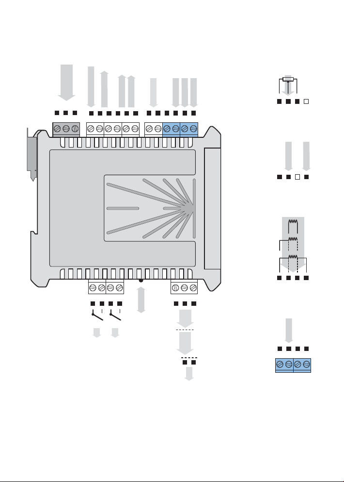
3. INSTRUMENT CONNECTION
232
485
POWER
LNE
-
+
AO - supply OC
+
+
L1
AO - frequency
-
OMX 100DC, PM, F
INPUT 2
INPUT 1
GND
-
INPUT 3
+
+
+
AO - voltage
+
Hold/Lock
AO - current
+
-
OMX 100DU
E
B
OMX 100PWR
INPUT I
INPUT U
GND
OMX 100RTD
ES-
ES+
S-
ES+
E-
S+
E-
S-
E+
OM Link
GND GND
RxD Rx/Tx+
TxD
L2
232
Rx/Tx-
485
+
Exc.
-
OMX 100T/C
INPUT
GND-CJC
+
7
INSTRUCTIONS FOR USE OMX 100
4. INSTRUMENT SETTING
The instrument is set and controlled by 5 control keys located on the front panel. By means of these controls it is
possible to browse through the operating program and to select and set the required values.
Input value
+ 3 digit optional
projection of meas.unit
Relay status - red LED
ON number is alight
OFF number is not alight
OFF number is flashing
limits w/restriction
(hysteresis, delay)
Signalization - green LED
ON LED is alight
ON LED is flashing
error statement
OFF LED is not alight
SYMBOLS USED IN THE INSTRUCTIONS
DC AC PM DU OHM RTD T/C
INPUT
OUTPUT
12
Output value
+ 3 digit optional
projection of meas.unit
Control keys
Indicates the setting for given type of instrument
CONTROL KEYS FUNCTIONS
+
Measuring mode
UP* LEFT* UP + LEFT
tare/resetting tare projection access into menu
Moving around in the menu
move to next item return to previous level confirm selected item
Setting/selection - items
move up move down confirm selected item
Setting - numbers
change of current figure - up - move to higher decade confirm selected number
* control keys react after being released
8
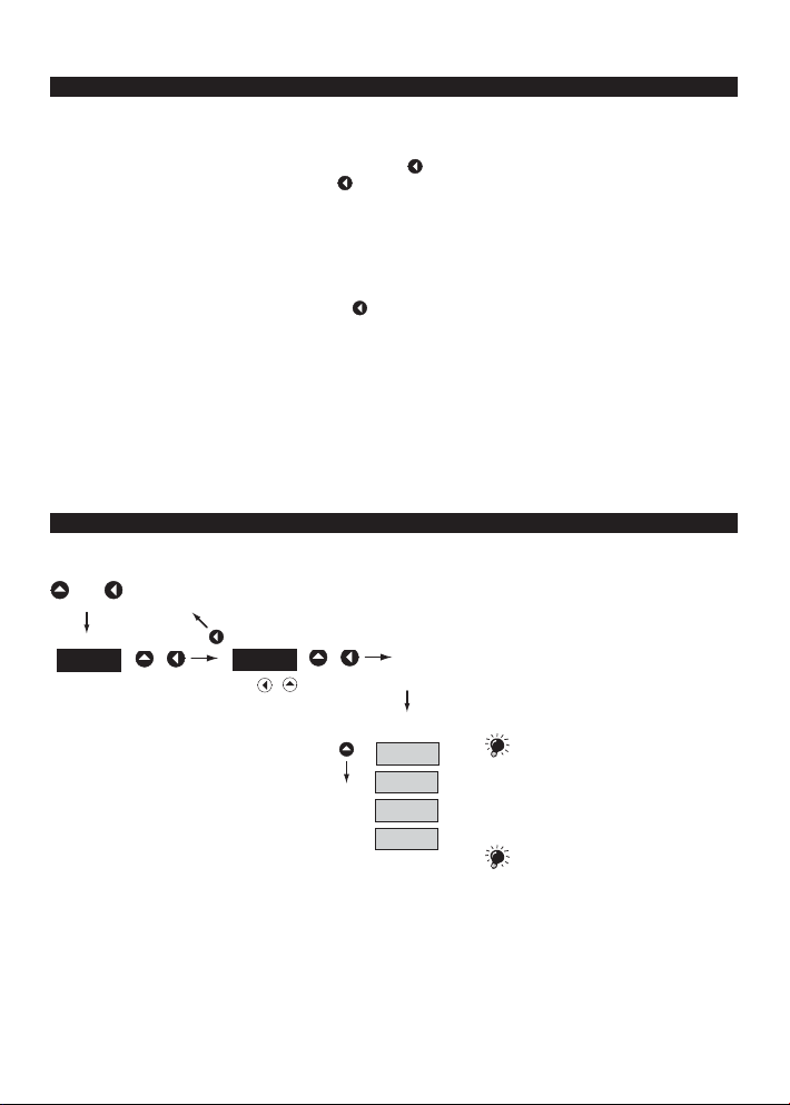
4. INSTRUMENT SETTING
SETTING THE DECIMAL POINT AND THE (-) SIGN
DECIMAL POINT
Its selection in the setting mode is performed by control key with transition behind the highest decade, when the
data starts flashing. Positioning is performed by
For projection of value exceeding 999 the „k“ suffix may be set up (display value is multiplied by 1000, only for
frequency output).
MINUS SIGN
Setting the minus sign is performed by control key on the higher decade. When editing the item, figures change
in numeric row 0,1…9,-,0,1
ACCESS INTO THE CONFIGURATION MODE
.
+
PAS
w/o saving
+
000
shift left
+
9,8,7…
OK
CHA .
INP .
The code from manufacture is always
preset to 000. In case of loss of access
password it is possible to use the universal access
code "177"
OUT.
SER.
If the code is preset to 000 the access
into the menu is free, i.e. without call for
its setting
9
INSTRUCTIONS FOR USE OMX 100
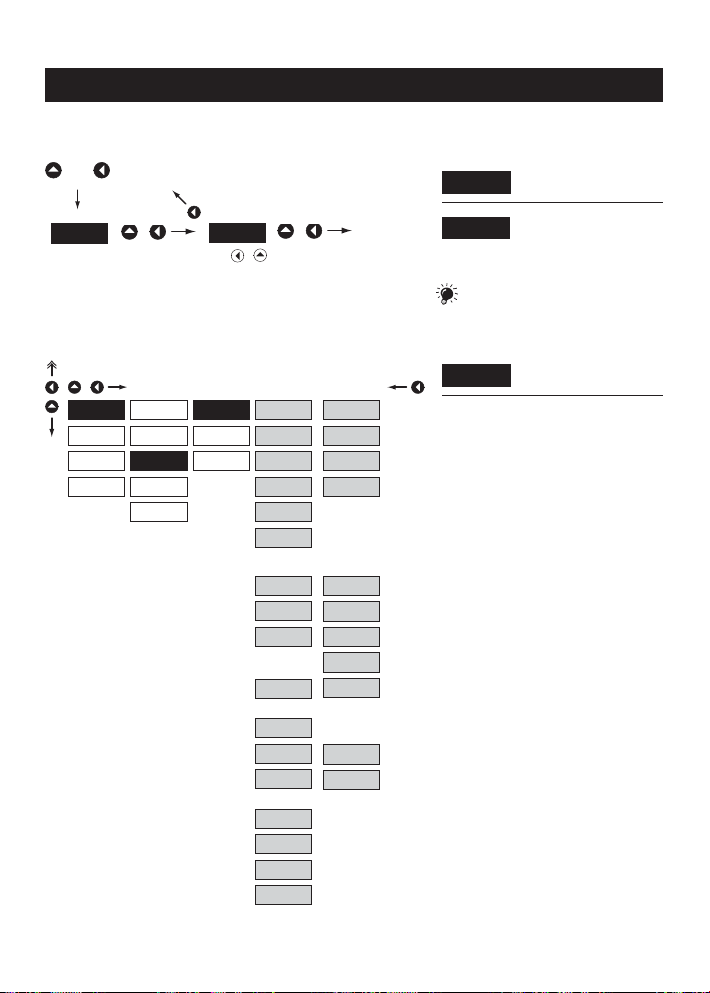
4.1 GUIDE THROUGH MINIMUM INSTRUMENT SETTING
Access into the „Configuration menu““
+
PAS
Selection of the measuring range/input type
+
INP.
CHA .
OUT.
SER.
w/o saving
+
CL. T.
CL. C.
CFG
AUX.
KEY
000
shift left
MOD
M.P.S.
CH.S.
+
9,8,7…
DC - 1
U 0.4
U 4
U 40
400
I 4
I 40
RTD
2-W
3-W
4-W
T/C
OK
DC - 2
60 m
150
I 1
I 5
PM
U 2
U 5
U 10
I 0
I 4
B
R
S
T
E
J
K
N
F
FRE .
COU .
password
its setting
DC Input
- setting the input range is dependant on the
ordered measuring range
PM Input
- setting the input range
RTD Input
- setting the type of connection
- in 2 or 3-wire connection it is necessary to link
the unconnected inputs (see the connection)
T/C Input
- setting the type of thermocouple is dependant
on the ordered measuring range
- B type B Range 1
R type R Range 2
S type S
T type T
E type E Range 3
J type J
K type K
N type N
Input F
- setting the measuring mode
- FRE. Frequency measurement
COU. Impulse counter
Entering the introductory
PAS
access password
Standard manufacture
000
setting of the access
If the code is preset to 000 the access
into „CM“ is free, i.e. without call for
Setting the instrument
MOD
measuring range
10

Setting the display projection
+
C. A.
A. O.
SET
FIL.
FOR .
DES .
TYP
MIN
MAX
MIN
MAX
I 5
I 4
E 4
I 20
U 2
U1 0
FRE .
OFF
INP.
CHA .
OUT.
SER.
Setting the analog output type - U/I
+
INP .
CHA .
OUT.
SER.
LIM
DAT .
DI S .
4. GUIDE THROUGH MINIMUM INSTRUMENT SETTING
Setting the display
MIN .
projection for minimum value
of the input signal
- range of the setting is -99…999
value of the input signal
- range of the setting is -99…999
DEF
Setting the display
MAX
projection for maximum
For type „F“ the items „SCA“ and „OFF“
will be displayed
Type - 0…5 mA
I 5
Type - 4…20 mA
I 4
Type - 4…20 mA with error
E 4
statement (3,0 mA)
Type - 0…20 mA
I 20
Type - 0…2 V
U 2
Type - 0…10 V
U1 0
Type - 0,2…2 200 Hz
FRE .
The output is off
OFF
Setting the analog output range - frequency
+
INP .
CHA .
OUT.
SER.
LIM
DAT .
DI S . MIN
A. O.
TYP
F. MI
F. MA
MAX
Setting the beginning of the
F. MI
frequency range for item
„MIN“
- range of the setting is 0,2…2 200 Hz
„MAX“
- range of the setting is 0,2…2 200 Hz
range
- range of the setting is -99…999
- range of the setting is -99…999
Setting the end of the
F. MA
frequency range for item
Assigning the display value
MIN
to the beginning of the AO
Assigning the display value
MAX
to the end of the AO range
11
INSTRUCTIONS FOR USE OMX 100
4.2 CONFIGURATION MENU
• designated for professional service and maintenance
• complete instrument setting
• access is protected by password or a shorting link on the input connector
23 .6
+
Upon delay longer than 30 s the programming mode is automatically discontinued and the instrument itself switches back to measuring mode
PAS
000
INP .
CHA .
CL. T. CFG .
Resetting internal values
SET FOR .
Setting
projection for
min/max input
signal
Entering the access password
CL. C
Counter
resetting
Auxiliary input
function
FIL.
Setting the
digital filters
Setting the
decimal point
OUT. LIM . DA T. A. O .
Setting
the limits,
hysteresis and
delay
Setting the
data output
Setting the
analog output
SER. RES. CA L N. PA.
Restoring
manufacture
setting/calibration
Instrument
calibration
Setting
new access
password
AUX.
Auxiliary input
function
DI S .
Mode of
display
projection
ID. .
Instrument
identification
KEY
Control key
function
Instrument setting
INP .
CHA
Instrument setting, calibration
OUT.
Setting the outputs
SER.
Service functions, authorization,
calibration
12

4.2.1 CONFIGURATION MODE - INPUT
+
CL. T.
INP.
CHA .
CL. C.
OUT.
SER.
4.2.1.1 INTERNAL VALUES RESETTING
+
INP.
CHA .
OUT.
SER.
CFG
AUX.
KEY
CL. T.
CFG
AUX.
KEY
4. INSTRUMENT SETTING - CONFIGURATION MODE
The basic instrument functions are set in
this menu
Internal values resetting
CL. T.
Counter resetting
CL. C.
Type „F“
Selecting the measuring
CFG
range and measuring rate
Setting the external control
AUX.
input function
Setting the control-key
KEY
function
Tare resetting
CL. T.
4.2.1.2 COUNTER RESETTING
+
CL. T.
INP.
CHA .
OUT.
SER.
CL. C.
CFG
AUX.
KEY
Counter resetting
CL. C.
Holds valid for mode „Counter“
F
13

INSTRUCTIONS FOR USE OMX 100
4.2.1.3.1 SETTING THE MEASURING RANGE
+
CL. T.
INP.
CHA .
OUT.
SER.
CL. C.
CFG
AUX.
MOD
M.P.S.
CH.S.
KEY
DC - 1
U 0.4
U 4
U 40
400
I 4
I 40
RTD
2-W
3-W
4-W
T/C
Setting the instrument
MOD
measuring range
DC - 2
60 m
150
I 1
I 5
PM
U 2
U 5
U 10
I 0
I 4
B
R
S
T
F
FRE .
COU .
E
J
K
N
DC Input
- setting the input range is dependant on the
ordered measuring range
- U 0.4 ±0,4 V Range 1
U 4 ±4 V
U 40 ±40 V
400 ±400 V
60 m ±60 mV Range 2
150 ±150 mV
I 1 ±1 A
I 5 ±5 A
PM Input
- setting the input range
RTD Input
- setting the type of connection
- in 2 or 3-wire connection it is necessary to link
the unconnected inputs (see connection)
T/C Input
- setting the type of thermocouple is dependant
on the ordered measuring range
- B type B Range 1
R type R Range 2
S type S
T type T
E type E Range 3
J type J
K type K
N type N
Input F
- setting the measuring mode
- FRE. Frequency measurement
COU. Impulse counter
14

4. INSTRUMENT SETTING - CONFIGURATION MODE
4.2.1.3.2 SHIFTING THE BEGINNING OF THE RANGE
+
CL. T.
INP.
CHA .
OUT.
SER.
4.2.1.3.3 COMPENSATION OF 2-WIRE CONDUCT
+
CHA .
OUT.
SER.
4.2.1.3.4 SETTING THE MODE OF ASSESSMENT OF CJC
+
OUT.
SER.
INP.
INP.
CFG
AUX.
KEY
CL. T.
CFG
AUX.
KEY
CL. T.
CFG
AUX.
KEY
MOD
R. Ad.
LEA .
M.P.S.
A. ST.
MOD
r. Ad.
LEA .
M.P.S.
A. ST.
MOD
CJC
T.C. J.
M.P.S.
YES
IN . 1
IN . 2CHA .
Ex . 1
Ex . 2
RTD OHM
Shifting the beginning of
R. Ad.
the measuring range
- in cases when it is necessary to shift the
beginning of the range by a given value, e.g.
when using sensor in measuring probe
- entered directly in Ohm
RTD OHM
Compensation of 2-wire
LEA .
conduct
- for measurement accuracy it is always
necessary to perform compensation of the
conduct in case of 2-wire connection
- entered directly in Ohm
- prior to confirmation of the displayed
challenge „YES“ it is necessary to substitute
the sensor at the end of the conduct by a
short circuit
- preset from manufacture to „0“
T/C
Mode of assessment of
C.J .C.
cold junction
- description of the mode of assessment of cold
junction is in chapter 5, page 30
Measurement without
IN . 1
reference thermocouple
- CJC measurement on the instrument brackets
- cold junction measurement on the instrument
brackets with anti-series connection of ref.
thermocouple
- whole measuring system operates under
identical and constant temperature
- when using compensation box
Measurement with reference
IN . 2
thermocouple
Measurement without
Ex . 1
reference thermocouple
Measurement with reference
Ex . 2
thermocouple
15

INSTRUCTIONS FOR USE OMX 100
4.2.1.3.5 SETTING THE TEMPERATURE OF CJC
+
CL. T.
INP.
CHA .
OUT.
SER.
4.2.1.3.6 SETTING THE TIME BASE
+
CHA .
OUT.
SER.
Valid for the „Frequency“ mode
4.2.1.3.7 SETTING THE INPUT FILTER PARAMETERS
+
CHA .
OUT.
SER.
INP.
INP.
CFG
AUX.
KEY
CL. T.
CFG
AUX.
KEY
CL. T.
CFG
AUX.
KEY
MOD
CJC
T.C. J.
M.P.S.
MOD
M. T.CL. t.
FIL.
BAC
A. ST.
MOD
M.T.CL. t.
FIL.
BAC
A. ST.
0.5
OFF
200
100
0.1
10
40
DEF
1
5
DEF
5
T/C
Setting the temperature
T.. C. J.
of CJC
- range 0…60°C with compensation box
Method and process of the setting of
CJC is described in separate chapter
on page 31
F
Setting the measuring
M. T.
time - time base
- if you set the time of measurement e.g to 1s,
the measuring time is approximately from
1s to 2s (1 s + maximum one period of
measured signal). If no impulse comes within
2 s , it is understood that the signal has zero
frequency
- range of the setting of the time base is 0,5 s
to 10 s
- in the „RTC“ regime with projection of date
the set time determines the period of switching
between time/date, min. is 5 s, the date is
displayed for approximately 2,5
F
Setting the digital input
FIL.
filter
- through digital filter we may suppress
undesirable interfering impulses (e.g. relay
back-swings) on the input signal. The set
parameter indicates maximum possible
instrument frequency (Hz), which the
instrument may process without restriction
Valid for the „Counter“ mode
When entering the contact and if we
know the maximum input frequency we
recommend using the filter
16

4. INSTRUMENT SETTING - CONFIGURATION MODE
4.2.1.3.8 SETTING THE DISPLAY STATUS BACKUP
+
CL. T.
INP.
CHA .
OUT.
SER.
4.2.1.3.9 SETTING THE INSTRUMENT MEASURING RATE
+
OUT.
SER.
INP.
CFG
AUX.
KEY
CL. T.
CFG
AUX.
KEY
MOD
M.T.CL. t.
FIL.
BAC
A. ST.
MOD
M.P.S.
A. ST .
DI S .
ENB .
0.5
1. 2CHA .
2.5
5. 0
10. 0
20. 0
40. 0
80. 0
DEF
DEF
F
Setting the display status
BAC.
backup
- setting the restoration of display value after
power outage or instrument switchoff
After switch-on instrument
DI S .
resets itself to zero
After switch-on instrument
ENB .
reads the display status from
its memory
Valid for the „Counter“ mode
Setting the measuring
M.P.S.
rate
Rate - 0,5 measurements/s
0.5
Rate - 1,2 measurements/s
1. 2
Rate - 2,5 measurements/s
2.5
Rate - 5 measurements/s
5. 0
Rate - 10 measurements/s
10. 0
Rate - 20 measurements/s
20. 0
Rate - 40 measurements/s
40. 0
Rate - 80 measurements/s
80. 0
17

INSTRUCTIONS FOR USE OMX 100
4.2.1.3.10 SELECTION OF AUTOMATIC MENU PRESETTING
+
CL. T.
INP.
CFG
OUT.
SER.
When selecting „AUT.“ in type „F“ the decimal
point and description are preset in the range of
0,01 Hz…50,0 kHz. Limits and AO are set in kHz!
4.2.1.4 SELECTION OF EXTERNAL INPUT FUNCTION
+
INP. LOC .
CHA .
OUT.
SER.
AUX.
KEY
CL. T.
CFG
AUX.
KEY
MOD
M. P.S.
A. ST.
AU. 1
ENA .
DI S .CH A.
HLD.
TAR .
CL. C.
DEF
DEF
DC PM
Menu presetting
CH.S.
Enable
ENA .
- depending on the set input the following items
will be preset automatically:
- CHANNELS: MIN/MAX, FOR, DES
- OUT: A.O. > MIN/MAX
- aut. preset items will disappear from the menu
and reappear again after setting „MAN“
- example for input 4-20mA (PM):
MIN/MAX > 4-20; FOR > 00.0; DES > mA;
A.O. MIN/MAX > 4-20
- as a standard, according to individual items
on the menu
„COU“
Disable
DI S .
Selection of external input
AU 1
function
LOCK, locking the control
LOC .
keys on the instrument
HOLD, stop measuring of
HLD.
the entire instrument
TARE - Tare* activation
TAR .
Counter resetting
CL. C.
only for type „F“, mode
OHM
F
4.2.1.5 SET TING ANOTHER FUNCTION OF THE CONTROL KEY „ENTER“
+
CL. T.
INP. ENB .
CHA .
OUT.
SER.
18
CFG
AUX.
KEY
ALL
DEF
DI S .
Setting another function
ALL
of the control key
Without function
DI S .
Activation of keys for Tare*
ENB .
projection, in type „F“ in
mode „COU“ > resetting to zero
* only for type DC, PM, DU, F

4. INSTRUMENT SETTING - CONFIGURATION MODE
19

INSTRUCTIONS FOR USE OMX 100
4.2.2 CONFIGURATION MODE - CHANNELS
+
INP . SET
CHA.
OUT.
SER.
Items „MIN“ and „MAX“ resp. „SCA“ and „OFF“ are
displayed only when the menu is set to „Manual“
INP > CFG > CH.S > MAN
4.2.2.1 DISPLAY PROJECTION
+
INP .
CHA.
OUT.
SER.
+
INP .
CHA.
OUT.
SER.
FIL.
FOR .
DES .
SET
FIL.
FOR .
DES .
SET
FIL.
FOR .
DES .
MIN
MAX
SCA
OFF
Only for type „F“
In this menu instrument parameters are set
Setting the display
SET
projection for minimum/
maximum value of the input signal
Input type Setting options
DC
AC
PM
DU
OHM
RTD
T/C
F
of the input signal
- range of the setting is -99…999
input signal
- range of the setting is -99…999
- calibration constant is for the conversion of
input value to required display value
- by setting the minus value the direction of
counting changes, i.e. we count down
- range: -0,00001...999999,
- shifting the beginning of measurement by
a set value which will always be read upon
resetting the instrument to zero
- range: -99999...999999,
Setting the digital filters
FIL.
Setting the decimal point
FOR .
Setting the measuring units
DES .
DC PM
DU
Setting the display
MIN .
projection for minimum value
Setting display projection
MAX
for maximum value of the
Setting the calibration
SCA
constant
Setting the additive constant
OFF
„PRESET“
OHM
DEF
DEF
= 0
F
= 1
20

4.2.2.2 SET TING THE DIGITAL FILTERS
+
INP . MOD
CHA.
OUT.
SER.
4.2.2.3 SET TING THE DECIMAL POINT
+
INP . 000 .
CHA.
OUT.
SER.
SET
FIL.
FOR .
DES .
SET
FIL.
FOR.
CON .
00. 0
0. 00
FL. P.DES .
OFF
EXP .
RND.
4. INSTRUMENT SETTING - CONFIGURATION MODE
Setting the digital filters
FIL.
Setting the filtration constant
CON .
- this menu is always displayed after selection
of a particular type of filter
- the value is calculated from a number of
measurements selected in „CON“
- range 2…100
- it is set by an optional number which
determines the projection step
(e.g. step 2,5 - 0, 2.5, 5, 7.5, etc.)
- the instrument allows classic projection of a
number with placement of the decimal point
as well as projection with floating point,
allowing to display the number in its most
precise form „FL.P.“
Filters are off
OFF
Selection of exponential
EXP
filter
Rounding the measured
RND.
value
DC PM
DU
Setting the decimal point
FOR .
Setting the DP
000.
Setting the DP
00. 0
Setting the DP
0. 00
Setting the DP
FL. P.
OHM
F
21

INSTRUCTIONS FOR USE OMX 100
4.2.2.4 SET TING THE MEASURING UNITS DESCRIPTION
+
INP .
CHA.
OUT.
SER.
Set description
Table of symbols is on page 30
SET
FIL.
FOR .
DES.
Description position
INPUT
OUTPUT
ASCII symbol code
move to next code
number setting
DC PM
DU
Setting the projection of
DES
measuring units on the
display
- the instrument allows to add three symbols
to classic numeric formats. The setting is
performed by means of shifted ASCII code.
Upon the setting the upper number indicates
the symbol position, the lower line displays
entered symbol on the first position and on
the last two positions the code of the relevant
symbol from 0 to 95.
Description is cancelled by entering symbols
00
- instruments with input for temperature
measurement display °C as a standard
first line (upper) thousands and next line units
to hundreds
In „COU“ mode in type „F“ the projection
in format 000000 is divided in two parts,
OHM
F
22

4. INSTRUMENT SETTING - CONFIGURATION MODE
23

INSTRUCTIONS FOR USE OMX 100
4.2.3 CONFIGURATION MODE - OUTPUTS
+
INP .
CHA .
OUT.
SER.
4.2.3.1.1 LIMITS - TYPE OF RELAY SWITCHING
+
INP .
CHA .
OUT.
SER.
The process of setting the limit 2 is identical
with the setting for Limit 1
LIM
DAT .
A. O .
DI S
LIM
DAT .
A. O .
DI S .
L 1
L 2
TYP
LIM .
HYS.
TIM .
CLO .
OPE.
In this menu it is possible to set parameters
of the instrument output signals
Setting the type and the
LIM
switching of limits
Setting the type and the
DAT .
parameters of data output
Setting the type and the
A. O .
parameters of analog output
Display projection mode
DI S .
Setting the type of relay
Typ
evaluation
DEF
Relay switches on when
CLO .
condition is met
Rely switches off when
OPE.
condition is met
4.2.3.1.2 LIMITS - SETTING THE BOUNDS
+
OUT.
LIM
DAT .
A. O .
L 1
L 2
INP .
CHA .
SER.
The process of setting the limit 2 is identical
with the setting for Limit 1
24
TYP
LIM .
HYS.
TIM .DI S .
Setting the bounds for relay
LIM .
switch-on
- within full display rangee
- within full display rangee
- in range 0…99,9 s
Setting hysteresis only in
HYS.
(+) values
Setting the offset of the limit
TIM .
switch-on

4.2.3.2.1 DATA OUTPUT - RATE
+
INP .
CHA .
OUT.
SER.
4.2.3.2.2 DATA OUTPUT - ADDRESS
+
INP .
CHA .
OUT.
SER.
4.2.3.3.1 ANALOG OUTPUT - TYPE
LIM
DAT.
A. O .
DI S .
LIM
DAT.
A. O .
DI S .
BD
ADR.
BD
ADR.
1. 2
2.4
4. 8
9. 6
19. 2
38.4
DEF
4. INSTRUMENT SETTING - CONFIGURATION MODE
Setting the data output
DB
rate
Rate - 1 200 Baud
1. 2
Rate - 2 400 Baud
2.4
Rate - 4 800 Baud
4. 8
Rate - 9 600 Baud
9. 6
Rate - 19 200 Baud
19. 2
Rate - 38 400 Baud
38.4
Setting the instrument
ADR.
address
- setting within the range of 0…31
- manufacture setting 00
DEF
Setting the analog output
TYP
type
+
INP .
CHA .
OUT.
SER.
LIM
DAT .
A. O.
DI S .
TYP
MIN
MAX
I 5
I 4
E 4
I 20
U 2
U1 0
FRE .
OFF
DEF
Type - 0…5 mA
I 5
Type - 4…20 mA
I 4
Type - 4…20 mA with error
E 0
statement (3,0 mA)
Type - 0…20 mA
I 20
Type - 0…2 V
U 2
Type - 0…10 V
U1 0
Type - 0,2…2 200 Hz
FRE .
The output is off
OFF
25

INSTRUCTIONS FOR USE OMX 100
4.2.3.3.2 ANALOG OUTPUT - RANGE
+
INP .
CHA .
OUT.
SER.
4.2.3.4 DISPLAY PROJECTION
+
INP .
CHA .
OUT.
SER.
LIM
DAT .
DI S . MIN
LIM
DAT .
DI S .
A. O.
A. O.
TYP
F. MI
F. MA
MAX
REF.
MAX
1 s
OFF
Setting the analog output
A. O .
range
- analog output is isolated and its value
corresponds with the displayed data. It is fully
programmable, i.e. it allows to assign the AO
limit points to any two arbitrary points of the
entire measuring range
Setting the beginning of the
F. MI
frequency range for item
„MIN“
- range of the setting is 0,2…2 200 Hz
„MAX“
- range of the setting is 0,2…2 200 Hz
range
- range of the setting is -99…999
- range of the setting is -99…999
- it burdens the processor performance, i.e.
in fully equipped transmitter the arithmetic
operation may be slowed down
- after pressing the control key the display is
active after 60 s at max. projection rate
Setting the end of the
F. MA
frequency range for item
Assigning the display value
MIN
to the beginning of the AO
Assigning the display value
MAX
to the end of the AO range
Display projection mode
DI S .
Display refresh
REF
Display value is changing at
MAX
maximum rate
Display value is being
1 s
restored 1x per second
Display is off
OFF
26

4. INSTRUMENT SETTING - CONFIGURATION MODE
27

INSTRUCTIONS FOR USE OMX 100
4.2.4 CONFIGURATION MODE - SERVICE
+
INP .
CHA .
OUT.
SER.
4.2.4.1 RESTORATION OF MANUFACTURE SETTING
+
INP . SETRES.
CHA .
OUT.
SER.
RES.
CAL .
N. PA .
ID.
CAL .
N. PA .
ID.
The instrument‘s service functions are set
in this menu
Restoration of the
RES.
manufacture setting and
instrument calibration
setting
- in case of incorrect setting or calibration it is
- reading the manufacture calibration and
Input range calibration for
CAL .
„DU“ version
Setting new access
N. PA.
password
Instrument identification
ID.
Restoration of the
RES.
instrument manufacture
possible to return to manufacture setting. Prior
execution of the changes you will be asked to
confirm your selection „YES“
original setting of items in the menu (DEF)
28

4. INSTRUMENT SETTING - CONFIGURATION MODE
4.2.4.2 INPUT RANGE CALIBRATION
+
INP . RES.
CHA .
OUT.
SER.
Before pressing „ENTER“ the potentiometer
runner has to be at rest
4.2.4.3 SET TING NEW ACCESS PASSWORD
+
INP . RES.
CHA .
OUT.
SER.
4.2.4.4 INSTRUMENT IDENTIFICATION
CAL.
N. PA .
CAL .
N. PA.
MIN
MAX
ID.
ID.
DU
Input range calibration
CAL.
- when MIN is displayed move the
potentiometer runner into required minimum
position and confirm by „Enter“, calibration is
confirmed by the „OK“ notice
- when MAX is displayed move the
potentiometer runner into required maximum
position and confirm by „Enter“, calibration is
confirmed by the „OK“ notice
Setting new access
N. PA.
password for
„Configuration menu“
- this option allows to change the numeric code
its setting
which blocks the access into the instrument
„Configuration mode“. The range of the
numeric code is 0…999
If the code is preset to 000 the access
into the menu is free, i.e. without call for
+
INP . RES.
CHA .
OUT.
SER.
CAL .
N. PA.
ID.
Projection of the
ID.
instrument version
- the display shows the type identification of the
instrument with the number of revision
- instrument name - program version - SW date
e.g.: OMX, 100, PM2, 003, 000,
29

INSTRUCTIONS FOR USE OMX 100
5. TABLE OF SYMBOLS
The instrument allows to add two descriptive symbols to classic numeric formats (at the expense of the number of
displayed places). The setting is performed by means of shifted ASCII code. Upon modification the first two places
display the entered symbols and the last two places the code of the relevant symbol from 0 to 95. Numeric value of
given symbol equals the sum of the numbers on both axes of the table.
Description is cancelled by entering characters with code 00
01234567 01234567
00 !"#$%&'
88()*+,- ./
16 16 01234567
24 24 89 : ; <=> ?
32 32 @A B C D E F G
40 40 HI JKLMNO
48 48 PQ R S T UVW
56 56 XYZ[\]^_
64 64 `abcde fg
72 72 hi jklmno
80 80 pq r s t uvw
88 88 xyz { |}~
30

6. METHOD OF MEASURING OF CJC
6. METHOD OF MEASURING OF CJC
Istrument with input for temperature measurement with thermocouple allows for setting of two types of measurement
of the cold junction.
Measuring thermocouple
+
V
-
+
OM xxx T/C
Reference thermocouple
WITH REFERENCE THERMOCOUPLE
a reference thermocouple may be located in the same place as the measuring instrument or in place with stable
temperature/compensation box
when measuring with reference thermocouple set
when using a thermostat (a compensation box or environment with constant temperature) set in the instrument menu
T.C.J.. its temperature (applies for setting CJC to Ex. 2)
if the reference thermocouple is located in the same environment as the measuring instrument then set in the instru-
ment menu
by a sensor located in the instrument terminal board.
CJC to IN. 2. Based on this selection the measurement of the surrounding temperature is performed
+
J
-
J
2
1
-
CJC in the instrument menu to IN. 2 or EX. 2
WITHOUT REFERENCE THERMOCOUPLE
inaccuracy originating from the creation of dissimilar thermocouples on the transition point terminal-conductor of
the thermocouple is not compensated for in the instrument
when measuring without reference thermocouple set
when measuring temperature without reference thermocouple the error in the measured data may be even 10°C
(applies for setting
CJC to Ex. 1)
CJC in the instrument menu to IN. 1 or Ex. 1
31

INSTRUCTIONS FOR USE OMX 100
7. DATA PROTOCOL
The instruments communicate via serial line RS232 or RS485. For communication they use the ASCII protocol.
Communication runs in the following format:
ASCII: 8 bit, no parity, one stop bit
The transfer rate is adjustable in the instrument menu and depends on the control processor used. The instrument
address is set in the instrument menu in the range of 0 ÷ 31. The manufacture setting always presets the ASCII protocol,
rate of 9600 Baud, address 00. The type of line used - RS232 / RS485 - is determined by an exchangeable card
automatically identified by the instrument.
COMMANDS FOR INSTRUMENT OPERATION
The commands are described in specification you can find at www.orbit.merret.cz/rs.
A command consists of a number and a letter, where the letter size is of significance.
DETAILED DESCRIPTION OF COMMUNICATION VIA SERIAL LINE
Activity Type Protocol Data transferred
Data solicitation (PC)
Data transfer
(Instrument)
Command tranfer
(Instrument) - identification
Command confirmation (Instrument)
232 ASCII # A A <CR>
485 ASCII # A A <CR>
232 ASCII > R SP D D D D D (D) (D) <CR>
485 ASCII > R SP D D D D D (D) (D) <CR>
232 ASCII # A A 1 Y <CR>
485 ASCII # A A 1 Y <CR>
ASCII
232
485
ok ! A A <CR>
bad ? A A <CR>
ASCII
ok ! A A <CR>
bad ? A A <CR>
Legend
#
AA
<CR>
<SP>
NP
D
R
!
?
>
32
35 23
0...31
13 0D
32 20
30H...3F
33 21
63 3F
62 3E
Beginning of the command
H
Two signs of the inst. address (sent in ASCII - decades and units, ex."01")
Carriage return
H
Space
H
Number and command - command code
Data - usually signs "0"..."9","-","." ; (D) - dp. and (-) may prolong data
Relay status; zero bit corresponds with 1st relay, 1st bit with 2nd relay, etc.
H
Positive command confirmation (ok)
H
Negative command confirmation (bad)
H
Beginning of the transmitted data
H

8. ERROR STATEMENTS
ERROR CAUSE ELIMINATION
E. D.U.
E. D.O..
E. T.U.
E. T.O.
E. I.U.
E.I.O.
E.HW.
E.EE.
E.DT.
E.CL.
display underflow
number is too small (large negative) to be
displayed
display overflow
number is too large to be displayed
table underflow
number outside tablerange
table overflow
number outside tablerange
range underflow (A/D converter)
input signal is smaller than the one allowed
by instruments range
range overflow (A/D converter)
input signal is larger than the one allowed
by instruments range
some part of the instruments does not
function properly
EEPROM error
damaged data in EEPROM
DATA error
data in EEPROM outside the range
EEPROM error
memory is blank („DEF“ values presetting
has initialized)
change display projection
change display projection
change display projection or table range
change display projection or table range
change input signal value
change input signal value
when reported repeatedly send the instrument for repair
when reported repeatedly send the instrument for repair
information about performed automatic
data correction in EEPROM
„Def“ values will be used in emergency
but calibration data will be impaired
> send for repair
8. ERROR STATEMENTS
33

INSTRUCTIONS FOR USE OMX 100
34

35

INSTRUCTIONS FOR USE OMX 100
9. TECHNICAL DATA
INPUT
selectable in configuration menu DC
DC 1 ±4 mA < 200 mV Input 1
±40 mA < 200 mV Input 1
±400 mV 100 kOhm Input 2
±4 V 100 kOhm Input 2
±40 V 10 MOhm Input 3
±400 V 10 MOhm Input 3
DC 2 ±1 A < 150 mV Input 1
±5 A < 150 mV Input 1
±60 mV 100 kOhm Input 2
±150 mV 100 kOhm Input 2
range is fixed, as per order PWR
Range U: 0...10 V 100 kOhm Input 2
0...100 V 10 MOhm Input 2
0...150 V 10 MOhm Input 2
0...250 V 10 MOhm Input 2
0...450 V 10 MOhm Input 2
Range I: 0...60 mV 100 kOhm Input 1
0...150 mV 100 kOhm Input 1
0...300 mV 100 kOhm Input 1
0...1 A < 150 mV Input 1
0...5 A < 150 mV Input 1
selectable in configuration menu PM
0/4...20 mA < 400 mV Input 1
0...2 V 1 MOhm Input 2
0...5 V 1 MOhm Input 3
0...10 V 1 MOhm Input 3
range is fixed, as per order OHM
0...999 Ohm
0...9,99 kOhm
0...99,9 kOhm
Connection: 2, 3 or 4 wire
RTD
Pt xxxx -50°…450°C
Ni xxxx -50°...250°C
Type Pt: 100/500/1 000 Ohm, platinum couple
s α=0,00385Ohm/Ohm/°C
Type Ni: Ni 1 000/10 000, 5000 ppm/6180 ppm
Connection: 2, 3 or 4 wire
5...105 Ohm
selectable in configuration menu T/C
Type: J (Fe-CuNi) -200°...900°C
K (NiCr-Ni) -200°...1 300°C
T (Cu-CuNi) -200°...400°C
E (NiCr-CuNi) -200°...690°C
B (PtRh30-PtRh6) 300°...1 820°C
S (PtRh10-Pt) -50°...1 760°C
R (Pt13Rh-Pt) -50°...1 740°C
N (Omegalloy) -200°...1 300°C
DU
Lin.pot.supply. 2,5 VDC/6 mA
min. potentiometer resistance is 500 Ohm
F
Range: 0,02…50 kHz
Input: upon contact, TTL, PNP/NPN
Measuring mode: counter/frequency
Function: data backup, time backup, Preset
Filtration constant: 0/5/10/100/200 Hz
Time base: 0,1/0,5/1/5/10 s
Calibrat. coefficient: 0,01…9999 Hz
Preset: 0…9999
PROJECTION
Display: LCD with blue illumination,
2x 3 symbols + 2x description (3 symbols)
Projection: -99…999
DP: adjustable - in programming mode
INSTRUMENT ACURACY
TC: 100 ppm/°C
Accuracy: ±0,2 % of range + 1 digit
±0,3 % of range + 1 digit T/C, PWR
±0,05 % of range + 1 digit F
Resolution: 0,1°/1°C RTD
Rate: 0,5 - 1,2 - 2,5 - 5 - 10 - 20 - 40 - 80 measurements/s
Overload capacity: 10x (t < 100 ms), 2x (long-term)
Digital filter adjustable in configuration menu
Compensation of conduct: max. 20 Ohm RTD
Comp.of CJC: adjustable T/C
Functions: Tare - display resetting
Hold - stop measuring (upon contact)
Lock - control keys locking
OM Link: Company communication interface for operation,
Watch-dog: reset after 25 ms
Calibration: at 25°C and 40 % r.h.
1°C T/C
0°...98°C or automatic (99)
setting and update of instrument SW
36
* values apply for resistance load

9. TECHNICAL DATA
OUTPUTS
Analog: isolated,
programmable w/ resolution of max. 12 bit
Non-linearity: 0,2 % of the range
TC: 100 ppm/°C
Rate: response to change of value< 100 ms
Voltage: 0…2 V/5 V/10 V, on request ±5 V/±10 V
Current: 0…5/20 mA/4…20 mA, on request ±20 mA
- compensation of conduct up to 450 Ohm
Corrugation: 5 mV of residual corrugation at output voltage 10 V
Frequency: 0,2…2 200 Hz
isolated, programmable, open collector with the
option of external supply (max. 40 V) vie intervnal
resistance (5k6)
COMPARATOR
Type: digital, adjustable in menu
Limits: -99…999
Hysteresis: 0…999
Delay: 0…99,9 s
Outputs: 2x relays with switch-on contact
(230 VAC/30 VDC, 3 A)*
contact switching on < 50 ms
Relays: 1/8 HP 277 VAC, 1/10 HP 125 V, Pilot Duty D300
DATA OUTPUTS
Protocols: ASCII
Data format: 8 bit + no parity + 1 stop bit (ASCII)
Rate: 1 200…38 400 Baud
RS 232: isolated, two-way communication
RS 485: isolated, two-way communication,
addressing (max. 31 instrument)
EXCITATION
Adjustable: 12…24 VDC/20 mA, isolated
- cannot be combined with data output
POWER SUPPLY
Options: 24/110/230 VAC, 50/60 Hz, ±10 %, 5 VA
10…30 VDC/max. 150 mA, isolated
Protection: melting fuse inside the instrument
VAC (T 80 mA), VDC (T 630 mA)
MECHANIC PROPERTIES
Material: PP 66 (UL 94 -V0), blue
Dimensions: 113 x 98 x 35 mm
Installation: to DIN rail, width 35 mm
OPERATING CONDITIONS
Connection: connector terminal board, conductor cross section up
to 2,5 mm
2
Stabilisation period: within 15 minutes after switch-on
Working temp.: 0°…60°C
Storage temp.: -10°…85°C
Protection: IP20
Overvoltage categ.: EN 61010-1, A2
Insulation resist.:** for pollution degree II, cat. measuring III.
AC power supply > 600 V (BI), 300 V (DI)
DC power supply > 500 V (BI), 250 V (DI)
EMC: EN 61000-3-2+A12; EN 61000-4-2, 3, 4, 5, 8, 11;
EN 550222, A1, A2
** BI - Basic insulation, DI - Dual insulation
37

INSTRUCTIONS FOR USE OMX 100
10. INST.DIMENSIONS AND INSTALLATION
Side viewFront view
INPUT
OUTPUT
97 mm
12
35 mm
Installation to DIN rail of 35 mm width
38
113 mm

11. CERTIFICATE OF GUARANTEE
ge
perform
instrument.
o
a
- m
- in
- in
- u
- o
t
not apply for defects caused by:
. . .
ARANTEE
.. . . . . . . . . . . . .
S
YE
R
11. CERTIFICATE OF GUARANTEE
Product OMX 100 DC PWR PM DU RTD T/C OHM F
Type . . . . . . . . . . . . . . . . . . . .
Manufacturing No . . . . . . . . . . . . . . . . . . . .
. . .
Date of sale . . . . . . . . . . . . . . . . . . . .
. . . . . . . . . . . . . . .
A guarantee period of 24 months from the date of sale to the user applies to this instrument.
Defects occuring during this period due to manufacture error or due to material faults shall be eliminated free of
charge.
For instrument quality, function and construction the guarantee shall apply provided that the instrument was connected
and used in compliance with the instruction for use.
The guarantee shall not apply for defects caused by:
- mechanic damage
- in transport
- intervention of unqualified person incl. the user
- unavoidable event
- other unprofessional interventions
The manufacturer performs guarantee and post-guarantee repairs unless provided for otherwise.
ri
h
echanic dama
transport
navoidable event
li
n
Stamp, signature
39

INSTRUCTIONS FOR USE OMX 100
DECLARATION OF CONFORMITY
Assessment of conformity pursuant to Section 12, par. 4 b, d of Act No. 22/1997 Coll.
Company: ORBIT MERRET, spol. s r.o.
Klánova 81/141, 142 00 Prague 4, Czech Republic, IČO: 00551309
Manufacturer: ORBIT MERRET, spol. s r.o.
Vodňanská 675/30, 198 00 Prague 9, Czech Republic
The manufacturer declares at its full responsibility that the product presented hereunder meets all technical requirements, is safe for use when used under the terms and conditions determined by Orbit Merret, spol.s r.o., and that
our company has taken all steps to ensure conformity of all products of the type referred-to below, which are being
brought out to the market, with technical documentation and requirements of the appurtenant Ordinance.
Product: Digital transmitter to DIN rail
Type: OMX 100
Version: DC, PM, PWR, RTD, T/C, DU, OHM, F
Conformity is assessed pursuant to the following standards:
Electr. safety: EN 61010-1
EMC: EN 50131-1, chapt. 14 and chapt. 15
EN 50130-4, chapt. 7 EN 61000-4-11
EN 50130-4, chapt. 8 EN 61000-4-11
EN 50130-4, chapt. 9 EN 61000-4-2
EN 50130-4, chapt. 10 EN 61000-4-3
EN 50130-4, chapt. 11 EN 61000-4-6
EN 50130-4, chapt. 12 EN 61000-4-4
EN 50130-4, chapt. 13 EN 61000-4-5
EN 50130-5, chapt. 20
prEN 50131-2-1, article 9.3.1
EN 61000-4-8
EN 61000-4-9
EN 61000-3-2 ed. 2:2001
EN 61000-3-3: 1997, Cor. 1:1998, Z1:2002
EN 55022, chapt. 5 and chapt. 6.
As evidence serve the protocols of authorised and accredited organisations:
VTÚE Praha, examination laboratory No. 1158, accredited by ČIA
VTÚPV Vyškov, examination laboratory No. 1103, accredited by ČIA
Prague, 18. 12. 2003 Miroslav Hackl v.r.
General manager
40
TECHDOK - OMX 100 - 2004 - v.2.2 - en
 Loading...