

Orbit Merret OMB 451UNI, OMB 452UNI User Manual

GUARANTEE
YEARS
OMB 451UNI
OMB 452UNI
4 DIGIT PROGRAMMABLE
UNIVERSAL INSTRUMENT
DC VOLTMETER/AMMETER
PROCESS MONITOR
THERMOMETER FOR PT 100/500/1 000
THERMOMETER FOR THERMOCOUPLES
DISPLAYS FOR LIN. POTENTIOMETERS
OHMMETER
THERMOMETER FOR NI 1 000

SAFETY INSTRUCTIONS
Please, read the enclosed safety instructions carefully and observe them!
These instruments should be safeguarded by isolated or common fuses (breakers)!
For safety information the EN 61 010-1 + A2 standard must be observed.
This instrument is not explosion-safe!
TECHNICAL DATA
Measuring instruments of the OMB 450 series conform to the European regulation 89/336/EWG.
The instruments are up to the following European standards:
EN 55 022, class B
EN 61000-4-2, -4, -5, -6, -8, -9, -10, -11
Seismic capacity:
IEC 980: 1993, chapter 6
The instruments are applicable for unlimited use in agricultural and industrial areas.
CONNECTION
Supply of energy from the main line has to be isolated from the measuring leads.
ORBIT MERRET, spol. sr.o.
Vodnanska 675/30
19800 Prague 9
Czech Republic
Tel: +420 - 281040200
Fax: +420 - 281040299
e-mail: orbit@merret.cz
www.orbit.merret.cz
|
2
INSTRUCTIONS FOR USE OMB 450UNI

1. Contents . . . . . . . . . . . . . . . . . . . . . . . . . . . . . . . . . . . . . . . . . . . . . . . . . . . . . . . . . . . . . . . . . . . . . . . . . . . . . . . . . . . . . . . . . . 3
2. Instrument description . . . . . . . . . . . . . . . . . . . . . . . . . . . . . . . . . . . . . . . . . . . . . . . . . . . . . . . . . . . . . . . . . . . . . . . . . . . . . . . . . . . 4
3. Instrument connection . . . . . . . . . . . . . . . . . . . . . . . . . . . . . . . . . . . . . . . . . . . . . . . . . . . . . . . . . . . . . . . . . . . . . . . . . . . . . . . . . . . 6
4. Instrument setting . . . . . . . . . . . . . . . . . . . . . . . . . . . . . . . . . . . . . . . . . . . . . . . . . . . . . . . . . . . . . . . . . . . . . . . . . . . . . . . . . . . . . . . 8
Symbols used in the instructions . . . . . . . . . . . . . . . . . . . . . . . . . . . . . . . . . . . . . . . . . . . . . . . . . . . . . . . . . . . . . . . . . . . . . . . . . . . . . . . . . 10
Setting the DP and the (-) sign . . . . . . . . . . . . . . . . . . . . . . . . . . . . . . . . . . . . . . . . . . . . . . . . . . . . . . . . . . . . . . . . . . . . . . . . . . . . . . . . . . 10
Control keys function . . . . . . . . . . . . . . . . . . . . . . . . . . . . . . . . . . . . . . . . . . . . . . . . . . . . . . . . . . . . . . . . . . . . . . . . . . . . . . . . . . .11
Setting/permitting items into “USER” menu . . . . . . . . . . . . . . . . . . . . . . . . . . . . . . . . . . . . . . . . . . . . . . . . . . . . . . . . . . . . . . . . . . . . . . . . .11
5. Setting “LIGHT” menu . . . . . . . . . . . . . . . . . . . . . . . . . . . . . . . . . . . . . . . . . . . . . . . . . . . . . . . . . . . . . . . . . . . . . . . . . . . . . . . . . . . 12
5.0 Description “LIGHT” menu . . . . . . . . . . . . . . . . . . . . . . . . . . . . . . . . . . . . . . . . . . . . . . . . . . . . . . . . . . . . . . . . . . . . . . . . . . . . . . . 12
Setting input . . . . . . . . . . . . . . . . . . . . . . . . . . . . . . . . . . . . . . . . . . . . . . . . . . . . . . . . . . . . . . . . . . . . . . . . . . . . . . . . . . 16
Setting Limits . . . . . . . . . . . . . . . . . . . . . . . . . . . . . . . . . . . . . . . . . . . . . . . . . . . . . . . . . . . . . . . . . . . . . . . . . . . . . . . . . . 32
Setting analog output . . . . . . . . . . . . . . . . . . . . . . . . . . . . . . . . . . . . . . . . . . . . . . . . . . . . . . . . . . . . . . . . . . . . . . . . . . . . . . . . . . 34
Nastavení rozsahu bargrafu . . . . . . . . . . . . . . . . . . . . . . . . . . . . . . . . . . . . . . . . . . . . . . . . . . . . . . . . . . . . . . . . . . . . . . . . . . . . . 35
Nastavení LCD stupnice . . . . . . . . . . . . . . . . . . . . . . . . . . . . . . . . . . . . . . . . . . . . . . . . . . . . . . . . . . . . . . . . . . . . . . . . . . . . . . . . . 36
Setting of bargrahp . . . . . . . . . . . . . . . . . . . . . . . . . . . . . . . . . . . . . . . . . . . . . . . . . . . . . . . . . . . . . . . . . . . . . . . . . . . . . . . . . . 38
Selection of programming menu „LIGHT“/„PROFI“ . . . . . . . . . . . . . . . . . . . . . . . . . . . . . . . . . . . . . . . . . . . . . . . . . . . . . . . . . . . . 38
Restoration of manufacture setting . . . . . . . . . . . . . . . . . . . . . . . . . . . . . . . . . . . . . . . . . . . . . . . . . . . . . . . . . . . . . . . . . . . . . . . . . 39
Calibration - input range (DU) . . . . . . . . . . . . . . . . . . . . . . . . . . . . . . . . . . . . . . . . . . . . . . . . . . . . . . . . . . . . . . . . . . . . . . . . . . . . 40
Selection of instrument menu language version . . . . . . . . . . . . . . . . . . . . . . . . . . . . . . . . . . . . . . . . . . . . . . . . . . . . . . . . . . . . . . . 41
Setting new access password . . . . . . . . . . . . . . . . . . . . . . . . . . . . . . . . . . . . . . . . . . . . . . . . . . . . . . . . . . . . . . . . . . . . . . . . . . . . . 41
Instrument identification . . . . . . . . . . . . . . . . . . . . . . . . . . . . . . . . . . . . . . . . . . . . . . . . . . . . . . . . . . . . . . . . . . . . . . . . . . . . . . . . . 42
6. Setting “PROFI” menu . . . . . . . . . . . . . . . . . . . . . . . . . . . . . . . . . . . . . . . . . . . . . . . . . . . . . . . . . . . . . . . . . . . . . . . . . . . . . . . . . . 44
6.0 Description of “PROFI” menu . . . . . . . . . . . . . . . . . . . . . . . . . . . . . . . . . . . . . . . . . . . . . . . . . . . . . . . . . . . . . . . . . . . . . . . . . . . . 44
6.1 “PROFI” menu - INPUT
6.1.1 Resetting internal values . . . . . . . . . . . . . . . . . . . . . . . . . . . . . . . . . . . . . . . . . . . . . . . . . . . . . . . . . . . . . . . . . . . . . . . . . . 46
6.1.2 Setting measuring type, range, mode, rate, ... . . . . . . . . . . . . . . . . . . . . . . . . . . . . . . . . . . . . . . . . . . . . . . . . . . . . . . . . 47
6.1.3 Setting the Real Time . . . . . . . . . . . . . . . . . . . . . . . . . . . . . . . . . . . . . . . . . . . . . . . . . . . . . . . . . . . . . . . . . . . . . . . . . . . . 53
6.1.4 External input function selection . . . . . . . . . . . . . . . . . . . . . . . . . . . . . . . . . . . . . . . . . . . . . . . . . . . . . . . . . . . . . . . . . . . 53
6.1.5 Optional accessory functions of the keys . . . . . . . . . . . . . . . . . . . . . . . . . . . . . . . . . . . . . . . . . . . . . . . . . . . . . . . . . . . . 54
6.2 “PROFI” menu - CHANNEL
6.2.1 Setting measuring parameters (projection, filters, decimal point, description) . . . . . . . . . . . . . . . . . . . . . . . . . . . . . . . . 58
6.2.2 Setting mathematic functions . . . . . . . . . . . . . . . . . . . . . . . . . . . . . . . . . . . . . . . . . . . . . . . . . . . . . . . . . . . . . . . . . . . . . . 62
6.2.3 Selection of evaluation of min/max. value . . . . . . . . . . . . . . . . . . . . . . . . . . . . . . . . . . . . . . . . . . . . . . . . . . . . . . . . . . . 64
6.3 “PROFI” menu - OUTPUT
6.3.1 Setting data logging . . . . . . . . . . . . . . . . . . . . . . . . . . . . . . . . . . . . . . . . . . . . . . . . . . . . . . . . . . . . . . . . . . . . . . . . . . . . 66
6.3.2 Setting Limits . . . . . . . . . . . . . . . . . . . . . . . . . . . . . . . . . . . . . . . . . . . . . . . . . . . . . . . . . . . . . . . . . . . . . . . . . . . . . . . . . . 68
6.3.3 Setting data output . . . . . . . . . . . . . . . . . . . . . . . . . . . . . . . . . . . . . . . . . . . . . . . . . . . . . . . . . . . . . . . . . . . . . . . . . . . . . . 71
6.3.4 Setting analog output . . . . . . . . . . . . . . . . . . . . . . . . . . . . . . . . . . . . . . . . . . . . . . . . . . . . . . . . . . . . . . . . . . . . . . . . . . . . 72
6.3.5 Selection of display projection . . . . . . . . . . . . . . . . . . . . . . . . . . . . . . . . . . . . . . . . . . . . . . . . . . . . . . . . . . . . . . . . . . . . . 74
6.3.6 Selection of bargraph projection . . . . . . . . . . . . . . . . . . . . . . . . . . . . . . . . . . . . . . . . . . . . . . . . . . . . . . . . . . . . . . . . . . . 75
6.4 “PROFI” menu - SERVICE
6.4.1 Selection of programming menu „LIGHT“/„PROFI“ . . . . . . . . . . . . . . . . . . . . . . . . . . . . . . . . . . . . . . . . . . . . . . . . . . . . 82
6.4.2 Restoration manufacture setting . . . . . . . . . . . . . . . . . . . . . . . . . . . . . . . . . . . . . . . . . . . . . . . . . . . . . . . . . . . . . . . . . . . . 83
6.4.3 Calibration - input range (DU) . . . . . . . . . . . . . . . . . . . . . . . . . . . . . . . . . . . . . . . . . . . . . . . . . . . . . . . . . . . . . . . . . . . . . 84
6.4.4 Selection of instrument menu language version . . . . . . . . . . . . . . . . . . . . . . . . . . . . . . . . . . . . . . . . . . . . . . . . . . . . . . . 84
6.4.5 Setting new access password . . . . . . . . . . . . . . . . . . . . . . . . . . . . . . . . . . . . . . . . . . . . . . . . . . . . . . . . . . . . . . . . . . . . . 85
6.4.6 Instrument identification . . . . . . . . . . . . . . . . . . . . . . . . . . . . . . . . . . . . . . . . . . . . . . . . . . . . . . . . . . . . . . . . . . . . . . . . . . 85
7. Setting items into “USER” menu . . . . . . . . . . . . . . . . . . . . . . . . . . . . . . . . . . . . . . . . . . . . . . . . . . . . . . . . . . . . . . . . . . . . . . . . . . 86
8. Method of measuring of the cold junction . . . . . . . . . . . . . . . . . . . . . . . . . . . . . . . . . . . . . . . . . . . . . . . . . . . . . . . . . . . . . . . . . . 88
9. Data protocol . . . . . . . . . . . . . . . . . . . . . . . . . . . . . . . . . . . . . . . . . . . . . . . . . . . . . . . . . . . . . . . . . . . . . . . . . . . . . . . . . . . . . . . . . 89
10. Error statements . . . . . . . . . . . . . . . . . . . . . . . . . . . . . . . . . . . . . . . . . . . . . . . . . . . . . . . . . . . . . . . . . . . . . . . . . . . . . . . . . . . . . . . 90
11. Table of symbols . . . . . . . . . . . . . . . . . . . . . . . . . . . . . . . . . . . . . . . . . . . . . . . . . . . . .
12. Technical data . . . . . . . . . . . . . . . . . . . . . . . . . . . . . . . . . . . . . . . . . . . . . . . . . . . . . . . . . . . . . . . . . . . . . . . . . . . . . . . . . . . . . . . . . 92
13. Instrument dimensions and instalation . . . . . . . . . . . . . . . . . . . . . . . . . . . . . . . . . . . . . . . . . . . . . . . . . . . . . . . . . . . . . . . . . . . . . 94
14. Certificate of guarantee . . . . . . . . . . . . . . . . . . . . . . . . . . . . . . . . . . . . . . . . . . . . . . . . . . . . . . . . . . . . . . . . . . . . . . . . . . . . . . . . . 95
Declaration of conformit y . . . . . . . . . . . . . . . . . . . . . . . . . . . . . . . . . . . . . . . . . . . . . . . . . . . . . . . . . . . . . . . . . . . . . . . . . . . . . . . . 96
. . . . . . . . . . . . . . . . . . . . . . . . . . . . . . . . . . 91
1CONTENTS
INSTRUCTIONS FOR USE OMB 450UNI
|
3

INSTRUMENT DESCRIPTION2
2.1 DESCRIPTION
The OMB 451/452 model series are programmable, three-color panel bargraphs with auxiliary display and adjustable
LCD scale. The instruments are designed as dimensional replacement of the ZEPAKOMP instruments. Available are types
UNI, PWR and UQC.
Type OM 402UNI is a multifunction instrument with the option of configuration for 8 various input options, easily configurable
in the instrumentmenu. By further options of input modules it is feasible to measure larger ranges of DC voltage and current
or increase the number of inputs up to 4 (applies for PM).
The instrument is based on an 8-bit microcontroller with a multichannel 24-bit sigma-delta converter, which secures high
accuracy, stability and easy operation of the instrument.
The OMB 451/452 is a multifunction instrument available in following types and ranges
type UNI
DC: 0…60/150/300/1 200 mV
PM: 0…5 mA/0…20 mA/4…20 mA/±2 V/±5 V/±10 V/±40 V
OHM: 0…100 Ϊ/0…1 kΪ/0…10 kΪ/0…100 kΪ/Auto
RTD-Pt: Pt 50/100/Pt 500/Pt 1 000
RTD-Cu: Cu 50/Cu 100
RTD-Ni: Ni 1000/Ni 10000
T/C: J/K/T/E/B/S/R/N/L
DU: Linear potentiometer (min. 500 Ϊ)
type UNI, option A
DC: 0…1 A/0…5 A/120 V/±250 V/±500 V
type UNI, option B (expansion by 3 more inputs)
PM:
3x 0…5 mA/0…20 mA/4…20 mA/±2 V/±5 V/±10 V/±40 V
PROGRAMMABLE PROJECTION
Selection: of type of input and measuring range
Measuring range: adjustable as fixed or with automatic change
Setting: manual, optional projection on the display may be set in the menu for both limit values of the input
signal , e.g. input 0…20 mA> 0…850,0
LCD scale: illuminated and freely programmable
Projection: -9999…9999 (-99999…999999)
COMPENSATION
of conduct: in the menu it is possible to perform compensation for 2-wire connection
of conduct in probe: internal connection (conduct resistance in measuring head)
of CJC (T/C): manual or automatic, in the menu it is possible to perform selection of the type of thermocouple and
compensation of cold junctions, which is adjustable or automatic(temperature at the brackets)
LINEARIZATION
Linearization:* by linear interpolation in50 points (solely via OM Link)
DIGITAL FILTERS
Floating average: from2…30 measurements
Exponen.average: from2…100 measurements
Rounding: setting the projection step for display
MATHEMATIC FUNCTIONS
Min/max. value: registration of min./max. value reached during measurement
Tare: designed to reset display upon non-zero input signal
|
4
INSTRUCTIONS FOR USE OMB 450UNI
* only for types DC, PM, DU

Peak value: the display shows only max. or min. value
Mat. operations: polynome, 1/x, logarithm, exponential, power, root, sin x
EXTERNAL CONTROL
Lock : control keys blocking
Hold : display/instrument blocking
Tare : tare activation/resetting tare to zero
Resetting MM : resetting min/max value
Memory: data storage into instrument memory
2.2 OPERATION
The instrument is set and controlled by five control keys located on the front panel. All programmable settings of the instrument
are performed in three adjusting modes:
LIGHT Simple programming menu
- contains solely items necessary for instrument setting and is protected by optional number code
PROFI Complete programming menu
- contains complete instrument menu and is protected by optional number code
USER User programming menu
- may contain arbitrary items selected from the programming menu (LIGHT/PROFI), which determine
the right (see or change)
- access without password
All programmable parameters are stored in the EEPROM memory (they hold even after the instrument is switched off).
Complete instrument operation and setting may be performed via OM Link communication interface,
which is a standard equipment of all instruments.
The operation program is freely accessible (www.orbit.merret.cz) and the only requirement is the
purchase of OML cable to connect the instrument to PC. It is manufactured in version RS 232 andUSB and is compatible
with all ORBIT MERRET instruments. Another option for connection is with the aid of data output RS 232 or RS 485 (without
the need of the OML cable).
The program OM LINK in „Basic“ version will enable you to connect one instrument with the option of visualization and
archiving in PC. The OM Link „Standard“ version has no limitation of the number of instruments connected.
2INSTRUMENT DESCRIPTION
2.3 OPTIONS
Excitation is suitable for supplying power to sensors and transmitters. It has a galvanic separation.
Comparators are assigned to monitor one, two, three or four limit values with relay output. The user may select limits regime:
LIMIT/DOSING/FROM-TO. The limits have adjustable hysteresis within the full range of the display as well as selectable
delay of the switch-on. Reaching the preset limits is signalled by LED and simultaneously by the switch-on of the relevant relay.
Data outputs are for their rate and accuracy suitable for transmission of the measured data for further projection or directly
into the control systems. We offer an isolated RS232 and RS485 with the ASCII or DIN MessBus protocol.
Analog outputs will find their place in applications where further evaluating or processing of measured data is required in
external devices. We offer universal analog output with the option of selection of the type of output - voltage/current. The
value of analog output corresponds with the displayed data and its type and range are selectable in Menu.
Measured data record is an internal time control of data collection. It is suitable where it is necessary to register measured
values. Two modes may be used. FAST is designed for fast storage (40 records/s) of all measured values up to 8000
records. Second mode is RTC, where data record is governed by Real Time with data storage in a selected time segment
and cycle. Up to 250 000 values may be stored in the instrument memory. Data transmission into PC via serial interface
RS232/485 andOM Link.
INSTRUCTIONS FOR USE OMB 450UNI
|
5

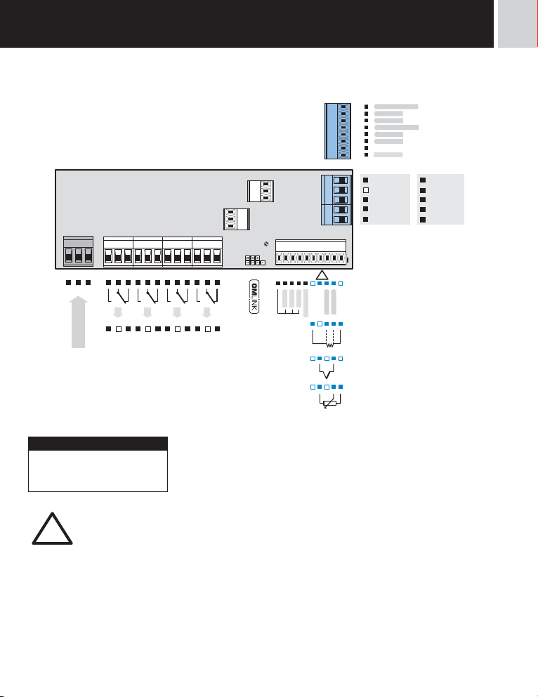
INSTRUMENT CONNECTION3
The instrument supply leads should not be in proximity of the incoming low-potential signals. Contactors, motors with larger
input power should not be in proximity of the instrument. The leads into the instrument input (measured quantity) should be
in sufficient distance from all power leads andappliances. Provided this cannot be secured it is necessary to use shielded
leads with connection to ground (bracket E).
The instruments are tested in compliance with standards for use in industrial area, yet we recommend to abide by the above
mentioned principles.
MEASURING RANGES
Type Input I Input U
DC
PM
OHM
RTD-Pt
RTD-Cu
RTD-Ni
T/C
DU
0…5/20 mA/4…20 mA ±2/±5/±10/±40 V
0…0,1/1/10/100 kΪ/Autorange
Pt 100/Pt 500/ Pt 1 000
Cu 50/100
Ni 1 000/10 000
J/K/T/E/B/S/R/N/L
Linear potentiometer (min. 500 Ϊ)
OPTION “A”
Type Input I Input U
DC
±0,1 A/±0,25 A/±0,5 A to GND (C)
±2 A/±5 A to GND (B)
0…60/150/300/1 200 mV
±100 V/±250 V/±500 V to GND (C)
|
6
INSTRUCTIONS FOR USE OMB 450UNI
123
-
+
L
N
POWER SUPPLY
3INSTRUMENT CONNECTION
OMB 451UQC
INPUT C2/Reset
+
INPUT B2
+
INPUT A2
+
INPUT C1/Reset
+
+
INPUT B1
+
INPUT A1
-
GND
ABCD EF GH
RxD/L+
TxD/L-
IV V VI
GND
III II I
GND
Analog output - I
Analog output - U
C 1
789
L2
E 2
C 2
10 11 12
L3
E 3
C 3
13 14 15
L4
E 4
C 4
Relays
Open collector
16 17 18 19 20 21 22 23
EXT. 3
456
E
L1
E 1
DB
CEA
!
-
+
+
GND
Excitation
INPUT - I
INPUT - U
EXT. 1
EXT. 2
S+ S- E--E+
S+
E+
ES+
-
+
-
2524
ES-ES-
+
+
INPUT - U
+
*GND - U/I0,5
-
*GND - I5
-
INPUT - I
+
CJC
DC, PM
RTD, OHM, Ni
T/C
DU
Excitation
Option A
INPUT - U
INPUT - U
GND - U
GND - I
INPUT - I
PWR
!
Excitation has the minus pole common with the
input - the bracket no. 22 - GND and you may set its
value by trimmer above the bracket no. 16
Maximum of 250 mA may be connected to “INPUT - I” (bracket no. 23) , i.e. 10-times range overload.
Mind the correct connection/mistaking of current - voltage input.
!
Destruction of measuring resistance in current input (15R) may occur.
INSTRUCTIONS FOR USE OMB 450UNI
|
7
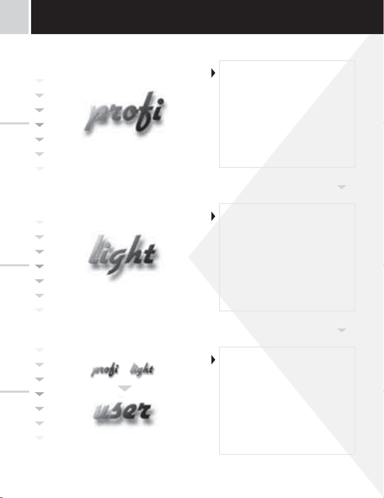
INSTRUMENT SETTING4
Setting PROFISetting LIGHT
• For expert users
• Complete instrument menu
• Access is password protected
• Possibility to arrange items of the
„User“ menu
• Tree menu structure
• For trained users
• Only items necessary for instrument
setting
• Access is password protected
• Possibility to arrange items of the
„User“ menu
• Linear menu structure
Setting USER
|
8
INSTRUCTIONS FOR USE OMB 450UNI
• For user operation
• Menu items are set by the user
(Profi/Light) as per request
• Access is not password protected
• Optional menu structure either tree
(PROFI) or linear (LIGHT)

4.1 SETTING
The instrument is set and controlled by five control keys located on the front panel. All programmable settings of the instrument
are performed in three adjusting modes:
LIGHT Simple programming menu
- contains solely items necessary for instrument setting and is protected by optional number code
PROFI Complete programming menu
- contains complete instrument menu and is protected by optional number code
USER User programming menu
- may contain arbitrary items selected from the programming menu (LIGHT/PROFI), which determine
the right (see or change)
- acces without password
All programmable parameters are stored in the EEPROM memory (they hold even after the instrument is switched off).
Complete instrument operation and setting may be performed via OM Link communication interface, which is a standard
equipment of all instruments.
The operation program is freely accessible (www.orbit.merret.cz) and the only requirement is the purchase of OML cable
to connect the instrument to PC. It is manufactured in version RS 232 and USB and is compatible with all ORBIT MERRET
instruments.
Another option for connection is with the aid of data output RS 232 or RS 485 (without the need of the OML cable).
Scheme of processing the measured signal
4INSTRUMENT SETTING
Input
CHAN. A
Linearization
FILTER
MAT.FCE.
Linearization
Min/Max
Relays
Analog
Data
Memory
Display
INSTRUCTIONS FOR USE OMB 450UNI
|
9

INSTRUMENT SETTING4
Setting and controlling the instrument is performed by means of 5 control keys located on the front panel. With the aid of
these keys it is possble to browse through the operation menu and to select and set required values.
Indication of measured input (red/green/orange LED)
Relay status
(red/green/orange LED)
ON the digit is lit
OFF the digit is not lit
OFF the digit is flashing
limits withrestriction
(hysteresis, delay)
Measured value (red/green LED)
the last two places may display
measuring units
0 500200 400100 300
LCD scale
Keys control
372.4~C
12T34
M
Indication of measured input
input number
(only for option “A”)
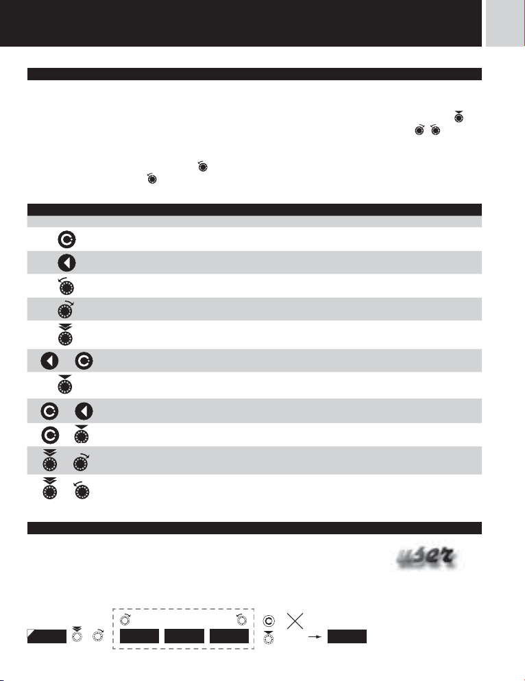
Symbols used in the instructions
DC PM DU OHM RTD T/C
DEF
values preset from manufacture
42
symbol indicates a flashing light (symbol)
MIN
inverted triangle indicates the item that can be placed in USER menu
CONNEC.
broken line indicates a dynamic item, i.e. it is displayed only in particular selection/version
(green LED)
Indicates the setting for given type of instrument
Function (green LED)
M Min/max. value
T Tare
increasing the value by rotating the ke to the right (UP)
decreasing the value by rotating the ke to the left (DOWN)
pressing the key shortly
pressing the key for longer than 2 seconds (> 2 s.),
after pressing the key the set value will not be stored
after pressing the key the set value will be stored
30
continues on page 30
|
10
INSTRUCTIONS FOR USE OMB 450UNI
Setting the decimal point and the minus sign
DECIMAL POINT
Its selection in the menu, upon modification of the number to be adjusted it is performed by the short push key
transition beyond the highest decade, when the decimal point starts flashing. Positioning is performed by / .
THE MINUS SIGN
Setting the minus sign is performed by the key
the current number (e.g..: 013 >
Control keys functions
Key Measurement Menu Setting numbers/selection
access into USER menu exit menu quit editing
programmable key function back to previous level move to higher decade
programmable key function move to previous item move down
programmable key function move to next item move up
, on class 100 > -87)
+
programmable key function move to next level confi rm setting/selection
+
+
+
+
direct access into PROFI menu
access into LIGHT/PROFI menu
on higher decade. When editing the item substraction must be made from
confi rm setting after selection
numeric value
numeric value is set to zero
confi guration of an item for
“USER” menu
determine the sequence of items
in “USER - LIGHT” menu
4INSTRUMENT SETTING
with
Setting items into „USER“ menu
• inLIGHT or PROFI menu
• no items permitted in USER menu from manufacture
• on items marked by inverted triangle
---
legend is flashing - current setting is displayed
+
NO YES SHOW
return to item
INSTRUCTIONS FOR USE OMB 450UNI
---
|
11

light
5
SETTING
5.0 SETTING “LIGHT”
LIGHT Simple programming menu
- contains only items necessary for instrument setting and is protected by optional number code
Setting LIGHT
light
• For capable users
• Only items necessary for instrument
setting
• Access is password protected
• Possibility to arrange items of the
„User“ menu
• Linear menu structure
Preset from manufacture
Password “0”
Menu LIGHT
USER menu of f
Setting the items
DEF
!
Upon delay exceeding 60 s the programming mode
is automatically discontinued and the instrument
itself restores the measuring mode
|
12
INSTRUCTIONS FOR USE OMB 450UNI

light
light
5SETTING
142.8 PASSW. 0
Type of instruments
OHMRTD
T/C
PMDC DUOHM
Limit 1 Limit 4Limit 3Limit 2
LIM . L.1 20 LIM . L.2 40 LIM . L.3 60 LIM . L.4 80
Setting type A.O. End A.O.Beginnig A.O.
TYP . A .O. MIN. A .O. MAX. A.O. 10004-20
Bargraph projection - beginning
Colour
DU
C. MIN. YES C. MAX. YES
Access password
+
Measuring range
PMTYP E
2-WIRECONNEC. 00000. oFO RM. A
EXT. 1TCCONNEC. 23C.J .TEM . FOR M. A 000000
0MIN A 100MAX A FO RM. A
Bargraph projection - end
0MIN. BG .
Menu type
CERV.CO LOR
4-20m AMODE
100MAX. BG.
MENU LIG HT
0000. oo
LCD scale division
Return to manufacture calibration
RE. CAL . YES
Calibration - only for “DU”
Selecting projection and connection
Level of LCD backlight
5 DIV.DIVIS.
Return to manufacture setting
RE. SET. YES
Option - comparator
Option - Analog output
100%BACKL.
Language selection
LANG. CZECH
Identifi cation
New password
PAS. LI. 0
Type of instruments
OMB 452UNI
Input
SW: version
65-001 4-20
Return to measur-
142.8IDENT . YES
ing mode
INSTRUCTIONS FOR USE OMB 450UNI
|
13
5
light
SETTING
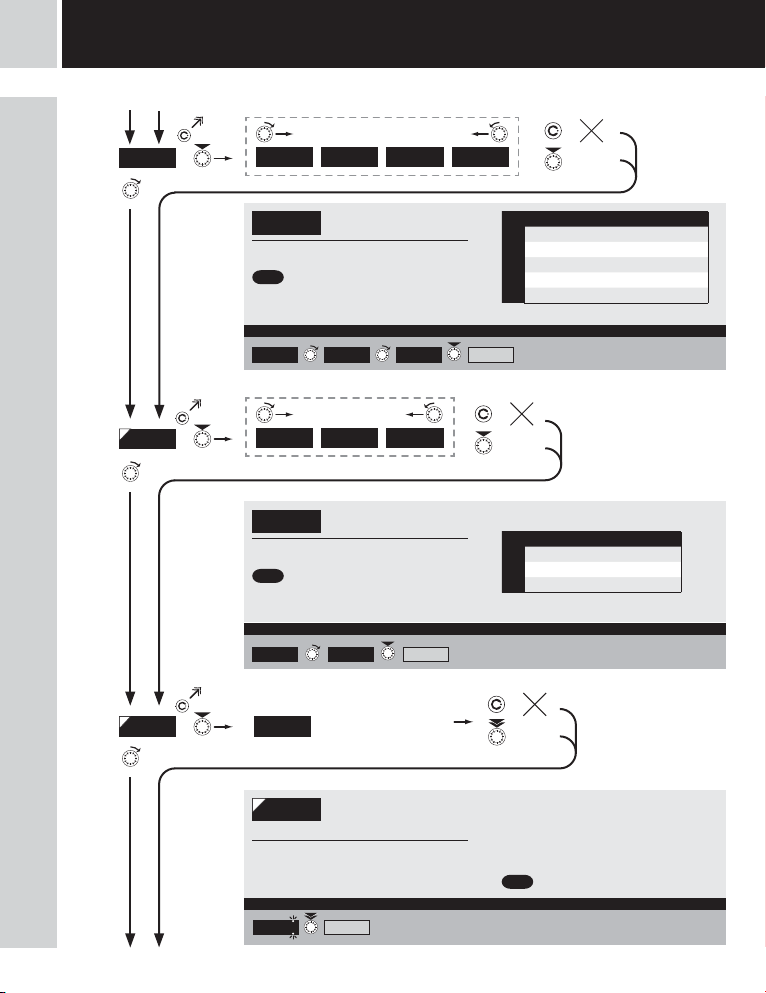
142.8
light
PASSW . 0
TYP E
Type „DC“ 16
18
Type “PM”
20
Type “OHM“
22
Type “RTD-Pt“
24
Type “RTD-Ni“
26
Type “T/C“
28
Type “DU”
30
Type “RTD-Cu“
|
14
INSTRUCTIONS FOR USE OMB 450UNI
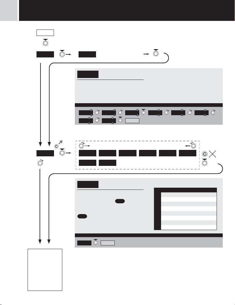
Entering access password
for access into the menu
Access into instrument
PASSW .
menu
PAS = 0
- access into menu is unrestricted, after
releasing keys you automaticaly move to first
item of the menu
Set „Pas sword” = 42 Example
0 1 2 02 12
32 TYP E
DC PM OHM RTD-P t RTD-Ni TC
DU
TYP E
- primary selection of the type of instrument
- performs default setting
from manufacture, incl. calibration
= “PM”
DEF
Type “PM” Example
42
RTD-Cu
Selection of the type of
instrument
of values
DEF
MODEPM
PAS > 0
- access into menu is protected ny number
code
22
Menu Type of instrument
DC DC voltmeter
PM Process monitor
OHM Ohmmeter
RTD-Pt Thermometer for sensors Pt
TYPE
RTD-Ni Thermometer for sensors Ni
TC Thermometer for thermocouples
DU Display for lin. potentiometer
RTD-Cu Thermometer for sensors Cu

light
light
SETTING
5
INSTRUCTIONS FOR USE OMB 450UNI
|
15
5
light
SETTING
light
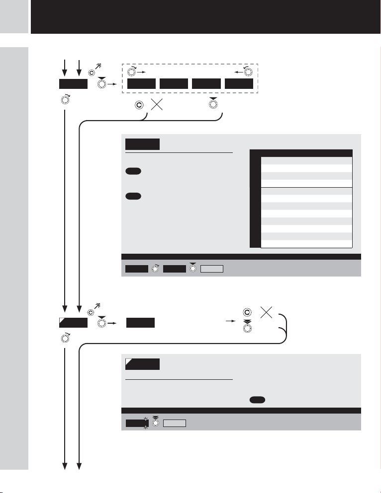
DC DC DC DC DC DC DC DC DC DC DC DC DC
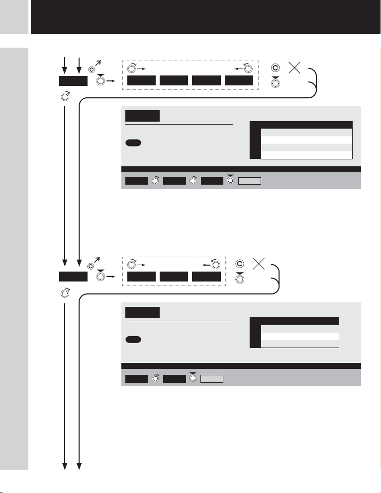
Type “DC”
MODE
MIN A
60 mV 150 mV 300 mV 12 00m V
Selection of the instrument
MODE
measuring range
= 60 mV
DEF
= 500 V*
DEF
* only for option “A”
Range ±150 mV Example
60 mV
150 mV MIN A
Setting for minimum
0
input signal
Menu Measuring range
60 mV ±60 mV
150 mV ±150 mV
MODE
300 mV ±300 mV
1200mV ±1,2 V
100 V ±100 V
250 V ±250 V
500 V ±500 V
0.10 A ±0,1 A
0.25 A ±0,25 A
MODE - A
0.50 A ±0,5 A
1.00 A ±1 A
5.00 A ±5 A
|
16
INSTRUCTIONS FOR USE OMB 450UNI
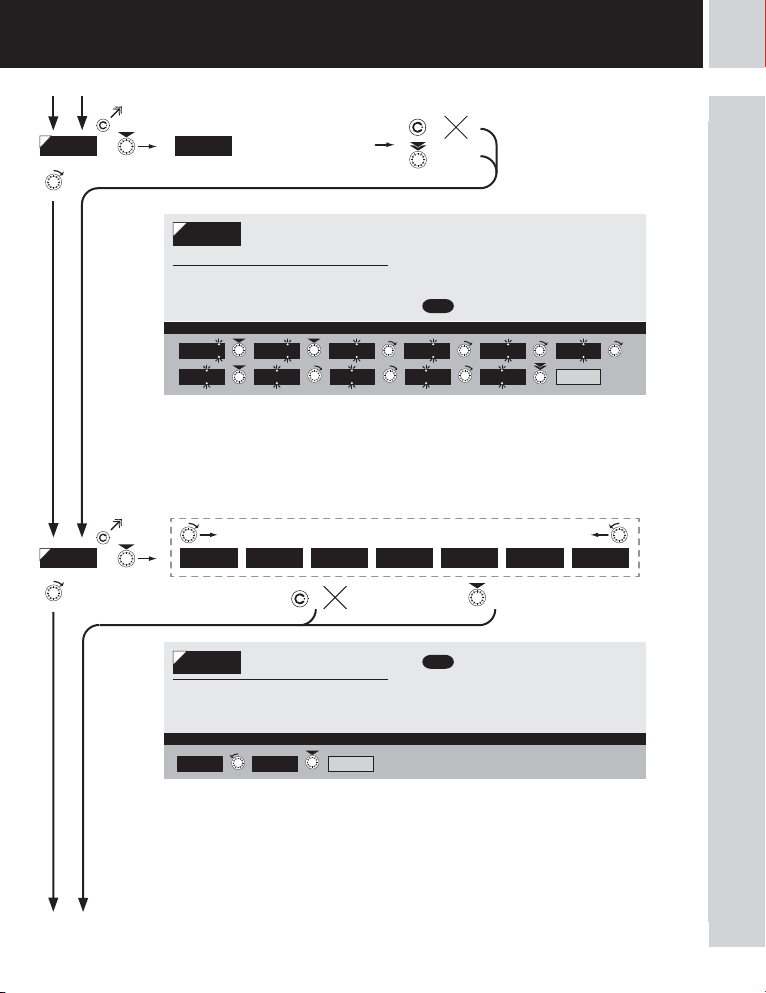
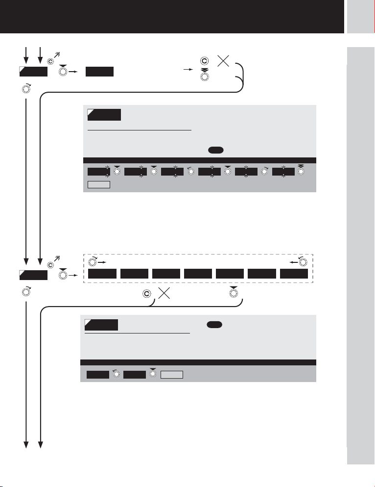
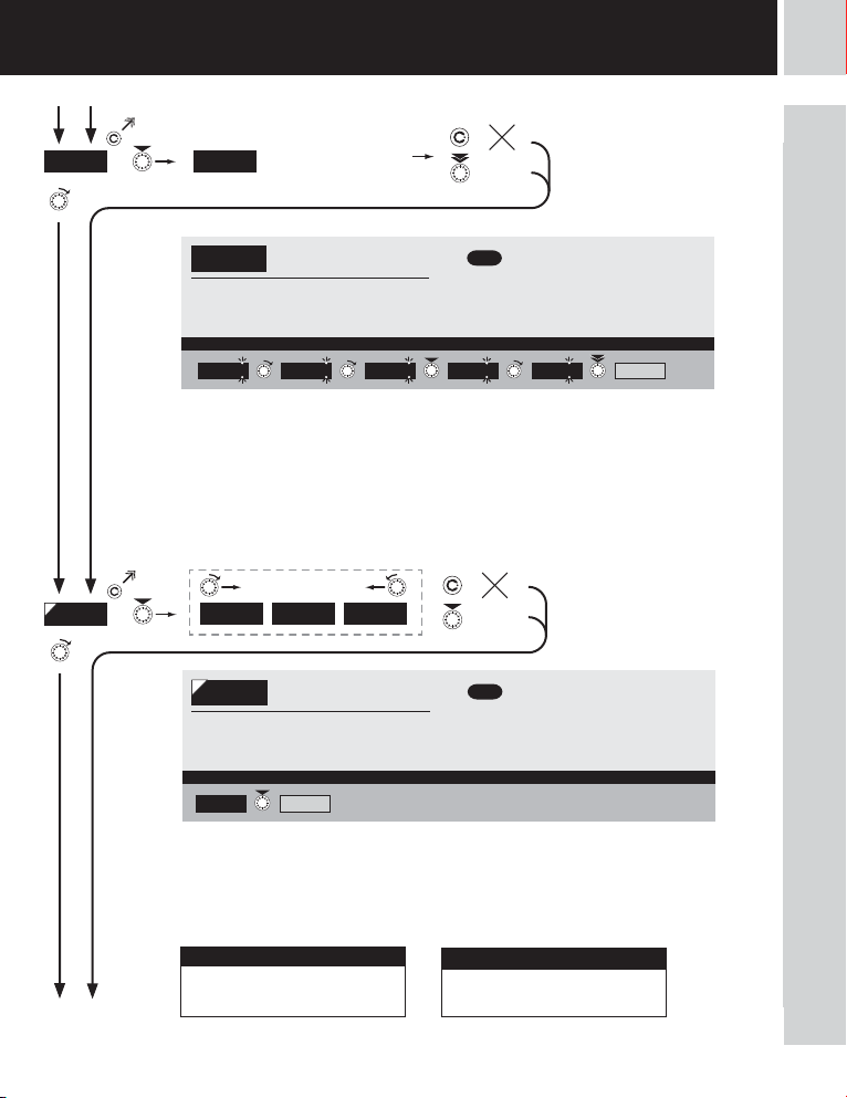
Setting display projection
MIN A
input signal
- range of the setting is -99999…999999
Projec tion for 0 mV > MI N A = 0 Example
for minimum value of
0 MAX A
- position of the DP does not affect display
projection
- the DP is automatically shifted after the
value is confirmed
= 0
DEF
light
light
SETTING
5
MAX A
FOR M. A
Setting for maximum
100
input signal
Setting display projection
MAX A
input signal
- range of the setting is -99999…999999
Projec tion for 150 mV > MA X A = 3500 Example
000000 00000.o 0000. oo 000. ooo 00 . oooo 0. ooooo FLO A. P.
for maximum value of
100 100 100
500
Setting projection of the
FOR M. A
decimal point
- positioning of the DP is set here in the
measuring mode
Projection of DP on display > 00000.o Example
MENU0000. oo 00000. o
- position of the DP does not affect display
projection
- the DP is automatically shifted after the
value is confirmed
= 100
DEF
3500 1500 2500
= 0000.oo
DEF
* subsequent item on the menu depends on instrument equipment
400 300 2 00
FORM . A 0500
DC DC DC DC DC DC DC DC DC DC DC DC DC
32
INSTRUCTIONS FOR USE OMB 450UNI
|
17
5
light
SETTING
light
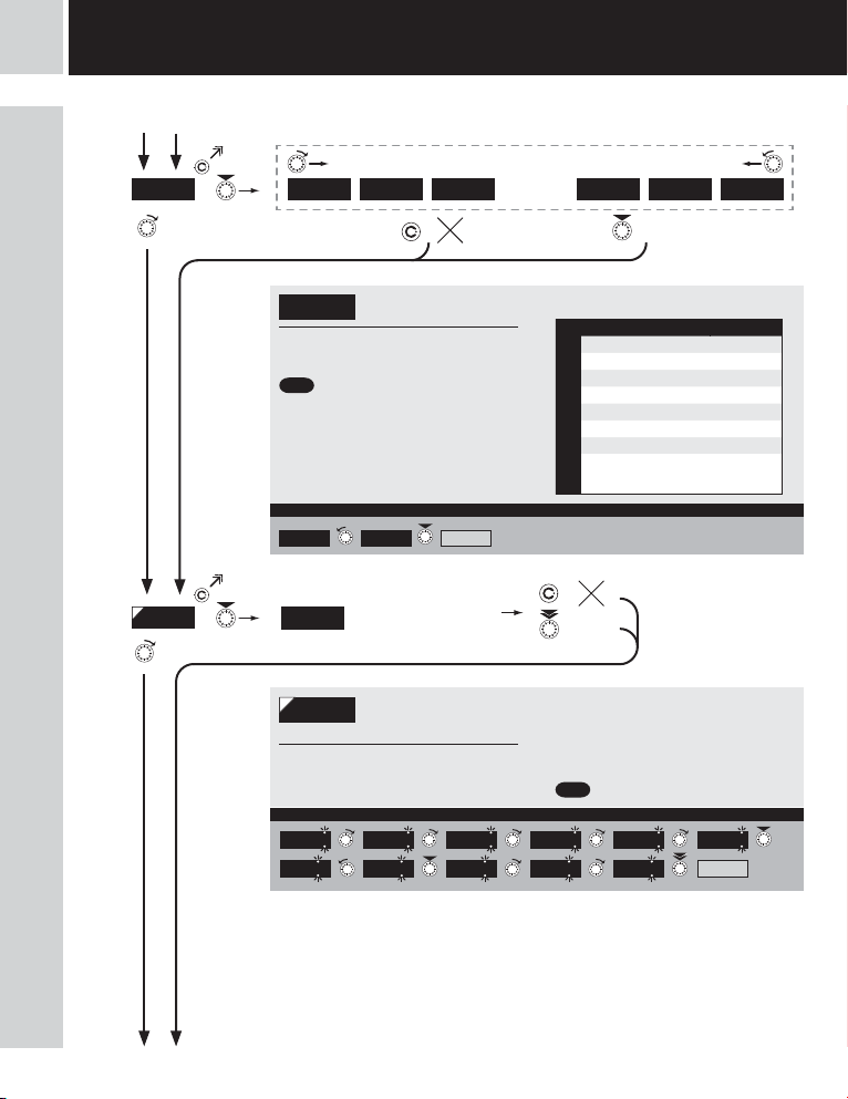
PM PM PM PM PM PM PM PM PM PM PM PM
Type “PM”
MODE
MIN A
0-5m A 0-20 mA 4-20 mA 0-10 V 0-40 V Er . 4
Selection of the instrument
MODE
measuring range
= 4 - 20 mA
DEF
Range 0… 20 mA Example
4-20m A 0-20 mA MIN A
Setting for minimum
0
input signal
Setting display projection
MIN A
0
05
for minimum value of
1
input signal
- range of the setting is -99999…999999
Projec tion for 0 mA > M IN A = -25 Example
• • •
Menu Range
0-5mA 0…5 mA
0-20mA 0…20 mA
4-20mA 4…20 mA
0-2 V ±2 V
0-5 V ±5 V
MODE
0-10 V ±10 V
0-40 V ±40 V
4…20 mA, with error statement of
Er.4-20
„underfl ow“ upon signal smaller
than 3,36 mA
- position of the DP does not affect display
projection
- the DP is automatically shifted after the
value is confirmed
= 0
DEF
-05 -5 -15 -25
5 4 32
MAX A
|
18
INSTRUCTIONS FOR USE OMB 450UNI
light
light
SETTING
5
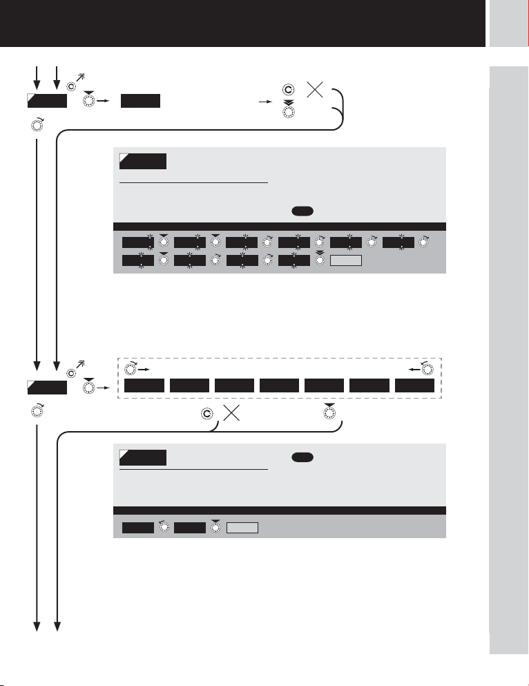
MAX A
FOR M. A
Setting for maximum
100
input signal
Setting display projection
MAX A
input signal
- range of the setting is -99999…999999
Projec tion for 20 m A > MAX A = 2500 Example
000000 00000 .o 0000. oo 000. ooo 00 . oooo 0. ooooo FLO A. P.
for maximum value of
100 100 100 400 300 200
Setting projection of the
FOR M. A
decimal point
- positioning of the DP is set here in the
measuring mode
Projection of DP on display > 00000.o Example
MENU0000. oo 00000. o
- position of the DP does not affect display
projection
- the DP is automatically shifted after the
value is confirmed
= 100
DEF
FORM . A500 1500 2500 0500
= 0000.oo
DEF
* subsequent item on the menu depends on instrument equipment
PM PM PM PM PM PM PM PM PM PM PM PM
32
INSTRUCTIONS FOR USE OMB 450UNI
|
19
light
5
SETTING
Type “OHM”
OHM OHM OHM OHM OHM OHM OHM OHM OHM
MODE
light
100 R 1 K 10 K 100 K
CONNEC.
MIN A
Selection of instrument
MODE
measuring range
= 100 Ϊ
DEF
Range 0…10 kΩ Example
100 R 1 K CONNEC.10 K
Menu Measuring range
100 R 0…100 Ϊ
1 k 0…1 kΪ
10 k 0…10 kΪ
MODE
100 k 0…100 kΪ
AUTO Autorange
2-WIRE 3-WIRE 4-WIRE
CONNEC.
DEF
Type of con nection - 3 w ire > CONECT. = 3 -WIRE Example
2-WIRE
Selection of the type of
sensor connection
= 2- WIRE
3-WIRE MIN A
Setting for minimum
0
input signal
Menu Connection
2-WIRE 2-wire
3-WIRE 3-wire
CONECT.
4-WIRE 4-wire
|
20
INSTRUCTIONS FOR USE OMB 450UNI
Setting display projection
MIN A
input signal
- range of the setting is -99999…999999
Projec tion for 0 Ω > MI N A = 0 Example
for minimum value of
0 MAX A
- position of the DP does not affect display
projection
- the DP is automatically shifted after the
value is confirmed
= 0
DEF
light
light
SETTING
5
MAX A
FOR M. A
Setting for maximum
100
input signal
Setting display projection
MAX A
input signal
- range of the setting is -99999…999999
Projec tion for 1 kΩ > M AX A = 1000 Example
FORM . A
000000 00000 .o 0000. oo 000. ooo 00 . oooo 0. ooooo FLO A. P.
for maximum value of
100 100 100 1000 0000 000
Setting projection of the
FOR M. A
decimal point
- positioning of the DP is set here in the
measuring mode
Projection of DP on display > 00000.o Example
MENU0000. oo 00000. o
- position of the DP does not affect display
projection
- the DP is automatically shifted after the
value is confirmed
= 100
DEF
= 0000.oo
DEF
* subsequent item on the menu depends on instrument equipment
OHM OHM OHM OHM OHM OHM OHM OHM OHM
32
INSTRUCTIONS FOR USE OMB 450UNI
|
21
5
light
SETTING
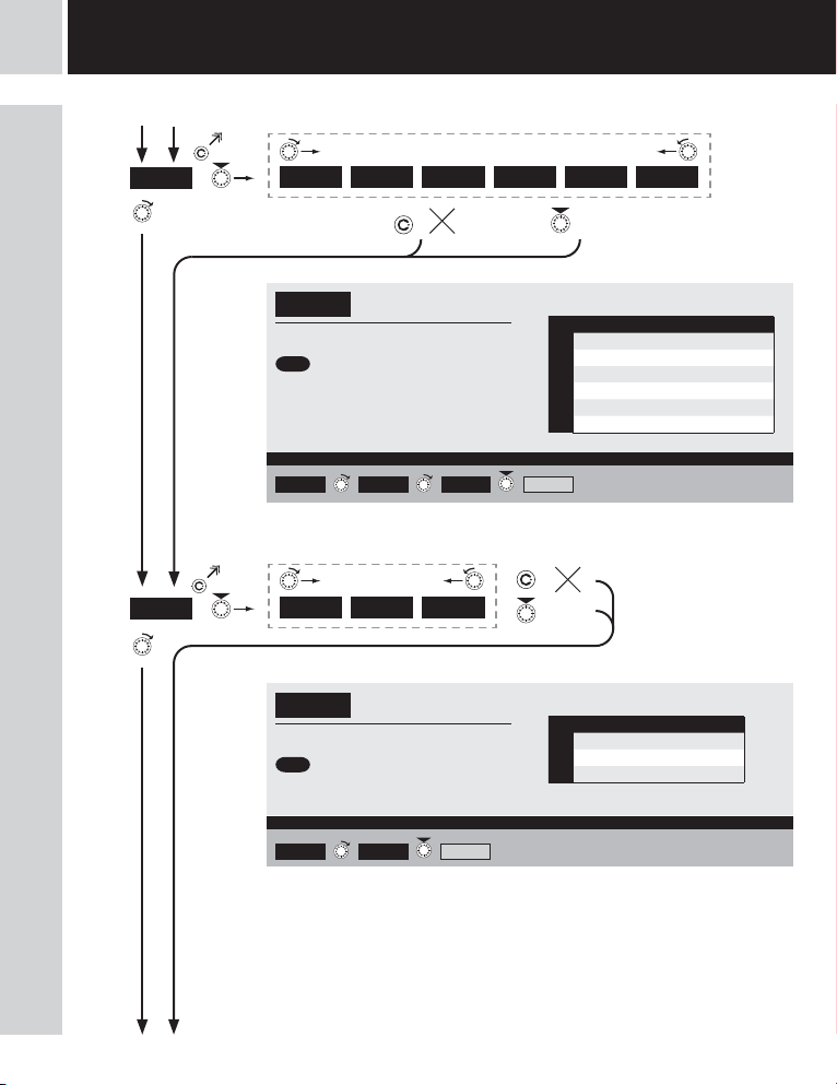
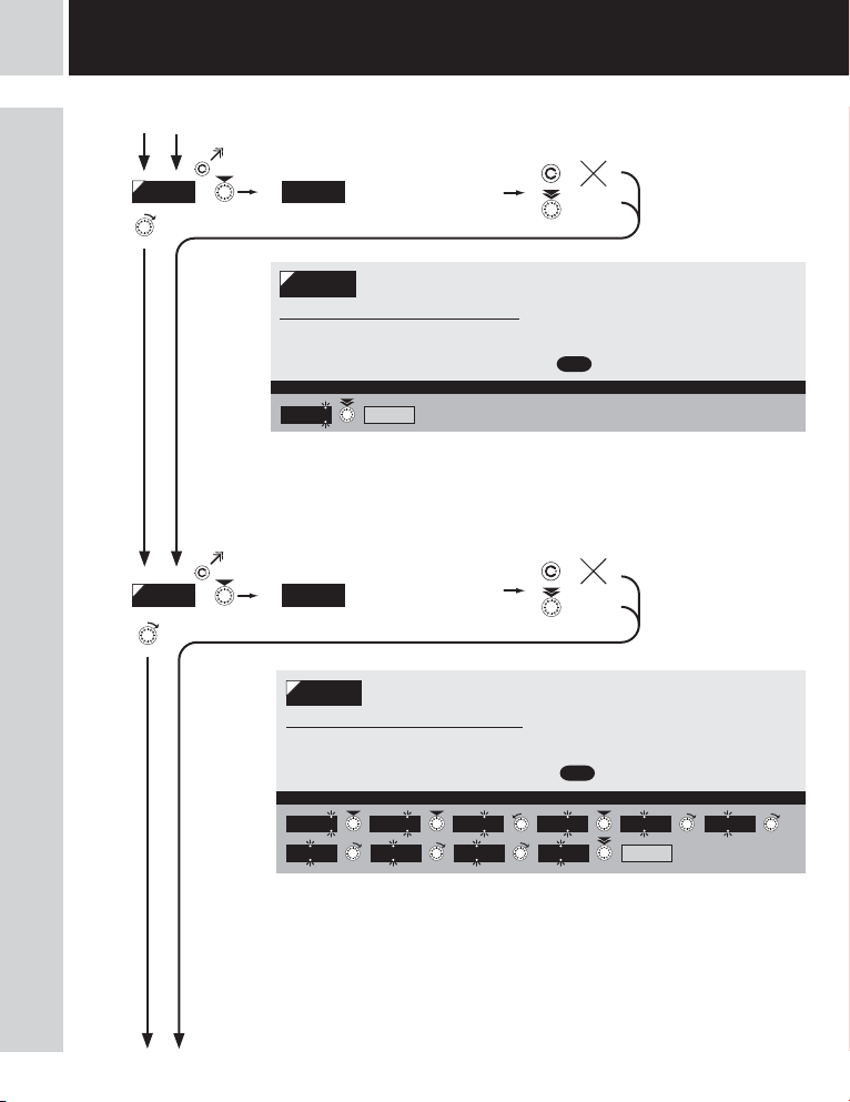
Type “RTD-Pt”
light
RTD - Pt RTD - Pt RTD - Pt RTD - Pt RTD - Pt RTD - Pt
MODE
CONNEC.
EU-100 EU-50 0 EU -1k0 US-100
Selection of instrument
MODE
measuring range
= Pt 100
DEF
MODE
Range - Pt 1 0 00 > MODE = EU -1k0 Example
EU-100 EU-50 0 CONNEC.EU-1k0
RU-100RU- 50
Menu Measuring range
EU-100 Pt 100 (3 850 ppm/°C)
EU-500 Pt 500 (3 850 ppm/°C)
EU-1k0 Pt 1000 (3 850 ppm/°C)
US-100 Pt 100 (3 920 ppm/°C)
RU-50 Pt 50 (3 910 ppm/°C)
RU-100 Pt 100 (3 910 ppm/°C)
2-WIRE 3-WIRE 4-WIRE
CONNEC.
DEF
Selection of the type of
sensor connection
= 2- WIRE
Menu Connectiion
2-WIRE 2-wire
3-WIRE 3-wire
CONECT.
4-WIRE 4-wire
|
22
INSTRUCTIONS FOR USE OMB 450UNI
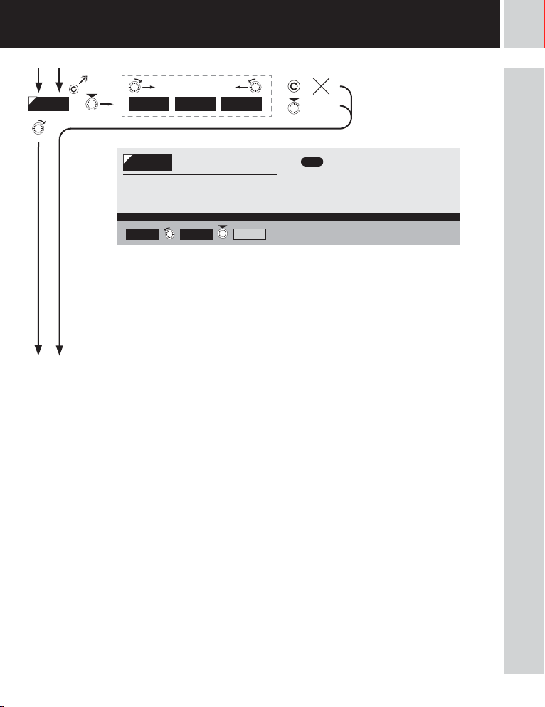
Type of con nection - 3 wi re > CONNEC . = 3-WIRE Example
2-WIRE
3-WIRE FOR M. A
light
light
SETTING
5
FOR M. A
32
000000 00000 .o 0000. oo
Setting projection of the
FOR M. A
decimal point
- positioning of the DP is set here in the
measuring mode
Projection of DP on display > 000000 Example
MENU00000. o 000000
= 00000.o
DEF
* subsequent item on the menu depends on instrument equipment
RTD - Pt RTD - Pt RTD - Pt RTD - Pt RTD - Pt RTD - Pt
INSTRUCTIONS FOR USE OMB 450UNI
|
23
5
light
SETTING
light
RTD - Ni RTD - Ni RTD - Ni RTD - Ni RTD - Ni RTD - Ni RTD - Ni
Type “RTD-Ni”
MODE
CONNEC.
5. 0- 1k 6. 2- 1k 5 .0-10k 6. 2-1 0k
Selection of instrument
MODE
measuring range
= Ni 1 000 - 5 000 ppm/°C
DEF
Range - Ni 10 0 00, 5 000 ppm > M ODE = 5.0-10 k Example
5.0- 1k 6 .2- 1k CONNEC.5. 0-1 0k
MODE
Menu Measuring range
5.0-1k Ni 1000 (5 000 ppm/°C)
6.2-1k Ni 1000 (6 180 ppm/°C)
5.0-10k Ni 10000 (5 000 ppm/°C)
6.2-10k Ni 10000 (6 180 ppm/°C)
2-WIRE 3-WIRE 4-WIRE
CONNEC.
DEF
Selection of the type of
sensor connection
= 2- WIRE
Menu Connection
2-WIRE 2-wire
3-WIRE 3-wire
CONECT.
4-WIRE 4-wire
|
24
INSTRUCTIONS FOR USE OMB 450UNI
Type of con nection - 3 w ire > CONNEC = 3 -WIRE Example
2-WIRE
3-WIRE FOR M. A

light
light
SETTING
5
FOR M. A
32
000000 00000 .o 0000. oo
Setting projection of the
FOR M. A
decimal point
- positioning of the DP is set here in the
measuring mode
Projection of DP on display > 000000 Example
MENU00000. o 000000
= 00000.o
DEF
* subsequent item on the menu depends on instrument equipment
RTD - Ni RTD - Ni RTD - Ni RTD - Ni RTD - Ni RTD - Ni RTD - Ni
INSTRUCTIONS FOR USE OMB 450UNI
|
25

light
5
SETTING
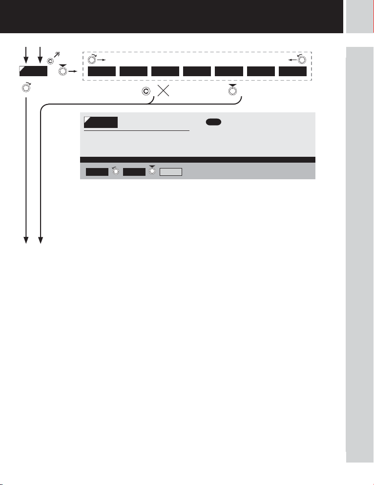
Type “T/C”
light
T/C T/C T/C T/C T/C T/C T/C T/C T/C T/C T/C
MODE
T/C B T/ C E T/ C J T/C K
>
T/C R T/ C S T/ C TT/C N
>
T/C L
CONNEC.
Selection of the type of
MODE
thermocouple
- setting the input range depends on the
measuring range ordered
= Type “J”
DEF
Type of thermocouple “K” Example
T/C J
T/C K
CONNEC.
Menu Type of thermocouple
T/C B B
T/C E E
T/C J J
T/C K K
T/C N N
MODE
T/C R R
T/C S S
T/C T T
T/C L L
INT.1TC INT.2TC
CONNEC.
DEF
Type of con nection > CO NECT. = EX T. 2TC Example
EXT.1TC EXT. 2TC C.J.TEM .
Selection of the type of
sensor connection
= EXT. 1TC
EXT.1TC
EXT. 2TC
Menu Connection Ref. T/C
measuring C.J. at
INT.1TC
instrument brackets
measuring C. J. at
instrument brackets
INT.2TC
with anti-series
connected ref. TC
the entire measuring
CONECT.
set is working under
EXT.1TC
invaried and constant
temperature
when using
EXT.2TC
compensation box
|
26
INSTRUCTIONS FOR USE OMB 450UNI
light
light
SETTING
5
C.J .TEM.
FOR M. A
DEF
= 23
Setting temperature of
23
cold junction
Setting temperature of cold
C.J .TEM.
junction
- range 0…99°C with compensation box
Setti ng temper ature of col d junction > C .J. TEM . = 35 Example
23 25 24 35 25 FORM . A
000000 00000 .o 0000. oo
Setting projection of the
FOR M. A
decimal point
- positioning of the DP is set here in the
measuring mode
Projection of DP on display > 000000 Example
MENU000000
* subsequent item on the menu depends on instrument equipment
DEF
= 000000
T/C T/C T/C T/C T/C T/C T/C T/C T/C T/C T/C
32
!
For thermocoule type “B” the items CONECT.
and C.J. TEM. are not available
!
Method and procedure of setting the cold junctions is
described in separate chapter on page 88
INSTRUCTIONS FOR USE OMB 450UNI
|
27
5
light
SETTING
light
DU DU DU DU DU DU DU DU DU DU DU DU DU
Type “DU”
MIN A
MAX A
Setting for minimum
0
input signal
Setting display projection
MIN A
input signal
- range of the setting is -99999…999999
Projec tion for the b eginnin g > MIN A = 0 Example
input signal
- range of the setting is -99999…999999
Projec tion for the e nd > MAX A = 500 0 Example
for minimum value of
0 MAX A
Setting for maximum
100
input signal
Setting display projection
MAX A
for maximum value of
100 100 100
2000
3000
4000 5000
- position of the DP does not affect display
projection
- the DP is automatically shifted after the
value is confirmed
= 0
DEF
- position of the DP does not affect display
projection
- the DP is automatically shifted after the
value is confirmed
= 100
DEF
10000 000 000
FORM . A
|
28
INSTRUCTIONS FOR USE OMB 450UNI
light
FOR M. A
light
000000 00000 .o 0000. oo 000. ooo 00 . oooo 0. ooooo FLO A. P.
SETTING
5
DU DU DU DU DU DU DU DU DU DU DU DU DU
- positioning of the DP is set here in the
measuring mode
Projection of DP on display > 00000.o Example
Calibration of the beginning and the end of
32
range of linear potentiometer is on page 40
FOR M. A
Setting projection of the
decimal point
= 0000.oo
DEF
* subsequent item on the menu depends on instrument equipment
MENU0000. oo 00000. o
INSTRUCTIONS FOR USE OMB 450UNI
|
29
 Loading...