

OM 652UC
6 DIGIT PROGRAMMABLE
IMPULSE COUNTER/FREQUENCY METER
STOPWATCH/TIMER
GUARANTEE
YEARS

2
|
INSTRUCTIONS FOR USE OM 652UC
SAFETY INSTRUCTIONS
Please, read the enclosed safety instructions carefully and observe them!
These instruments should be safeguarded by isolated or common fuses (breakers)!
For safety information the EN 61 010-1 + A2 standard must be observed.
This instrument is not explosion-safe!
TECHNICAL DATA
Measuring instruments of the OM 652 series conform to the European regulation 89/336/EWG
and the Ordinance 168/1997 Coll.
They are up to the following European:
EN 55 022, class B
EN 61000-4-2, -4, -5, -6, -8, -9, -10, -11
The instruments are applicable for unlimited use in agricultural and industrial areas.
CONNECTION
Supply of energy from the main line has to be isolated from the measuring leads.
ORBIT MERRET, spol. s r.o.
Vodňanská 675/30
198 00 Prague 9
Czech Republic
Tel: +420 - 281 040 200
Fax: +420 - 281 040 299
e-mail: orbit@merret.cz
www.orbit.merret.cz

INSTRUCTIONS FOR USE OM 652UC
|
3
1. Contens . . . . . . . . . . . . . . . . . . . . . . . . . . . . . . . . . . . . . . . . . . . . . . . . . . . . . . . . . . . . . . . . . . . . . . . . . . . . . . . . . . . . . . . . . . . . .3
2. Instrument description. . . . . . . . . . . . . . . . . . . . . . . . . . . . . . . . . . . . . . . . . . . . . . . . . . . . . . . . . . . . . . . . . . . . . . . . . . . . . . . . . . . . . . .4
3. Instrument connection . . . . . . . . . . . . . . . . . . . . . . . . . . . . . . . . . . . . . . . . . . . . . . . . . . . . . . . . . . . . . . . . . . . . . . . . . . . . . . . . . . . . . . .6
4. Instrument setting . . . . . . . . . . . . . . . . . . . . . . . . . . . . . . . . . . . . . . . . . . . . . . . . . . . . . . . . . . . . . . . . . . . . . . . . . . . . . . . . . . . . . . . . . . 8
Symbols used in the instructions . . . . . . . . . . . . . . . . . . . . . . . . . . . . . . . . . . . . . . . . . . . . . . . . . . . . . . . . . . . . . . . . . . . . . . . . . . . . . . . . . . . . 10
Setting the DP andthe (-) sing . . . . . . . . . . . . . . . . . . . . . . . . . . . . . . . . . . . . . . . . . . . . . . . . . . . . . . . . . . . . . . . . . . . . . . . . . . . . . . . . . . . . . 10
Control keys functions . . . . . . . . . . . . . . . . . . . . . . . . . . . . . . . . . . . . . . . . . . . . . . . . . . . . . . . . . . . . . . . . . . . . . . . . . . . . . . . . . . . . . 11
Configuration of „User“ menu items . . . . . . . . . . . . . . . . . . . . . . . . . . . . . . . . . . . . . . . . . . . . . . . . . . . . . . . . . . . . . . . . . . . . . . . . . . . . . . . . 11
5. Setting “LIGHT” menu
5.0 Description “LIGHT” menu . . . . . . . . . . . . . . . . . . . . . . . . . . . . . . . . . . . . . . . . . . . . . . . . . . . . . . . . . . . . . . . . . . . . . . . . . . . . . . . . . . 12
Access to menu. . . . . . . . . . . . . . . . . . . . . . . . . . . . . . . . . . . . . . . . . . . . . . . . . . . . . . . . . . . . . . . . . . . . . . . . . . . . . . . . . . . 14
Setting initial value . . . . . . . . . . . . . . . . . . . . . . . . . . . . . . . . . . . . . . . . . . . . . . . . . . . . . . . . . . . . . . . . . . . . . . . . . . . . . . . . 14
Selection of instrument measuring mode . . . . . . . . . . . . . . . . . . . . . . . . . . . . . . . . . . . . . . . . . . . . . . . . . . . . . . . . . . . . . . . 15
Selection of control START
H
. . . . . . . . . . . . . . . . . . . . . . . . . . . . . . . . . . . . . . . . . . . . . . . . . . . . . . . . . . . . . . . . . . . 15
Selection of control STOP
H
. . . . . . . . . . . . . . . . . . . . . . . . . . . . . . . . . . . . . . . . . . . . . . . . . . . . . . . . . . . . . . . . . . . 16
Selection of digital input filter. . . . . . . . . . . . . . . . . . . . . . . . . . . . . . . . . . . . . . . . . . . . . . . . . . . . . . . . . . . . . . . . . . . . . . . . 16
Selection of type of input A . . . . . . . . . . . . . . . . . . . . . . . . . . . . . . . . . . . . . . . . . . . . . . . . . . . . . . . . . . . . . . . . . . . . . . . . . 17
Setting level of input A . . . . . . . . . . . . . . . . . . . . . . . . . . . . . . . . . . . . . . . . . . . . . . . . . . . . . . . . . . . . . . . . . . . . . . . . . . . . . 17
Selection of type of input C (Resetting) . . . . . . . . . . . . . . . . . . . . . . . . . . . . . . . . . . . . . . . . . . . . . . . . . . . . . . . . . . . . . . . . 18
Setting level of input C (Resetting) . . . . . . . . . . . . . . . . . . . . . . . . . . . . . . . . . . . . . . . . . . . . . . . . . . . . . . . . . . . . . . . . . . . . 18
Setting multiplying constant . . . . . . . . . . . . . . . . . . . . . . . . . . . . . . . . . . . . . . . . . . . . . . . . . . . . . . . . . . . . . . . . . . . . . . . . . 19
Setting dividing constant . . . . . . . . . . . . . . . . . . . . . . . . . . . . . . . . . . . . . . . . . . . . . . . . . . . . . . . . . . . . . . . . . . . . . . . . . . . 19
Setting offset - PRESET . . . . . . . . . . . . . . . . . . . . . . . . . . . . . . . . . . . . . . . . . . . . . . . . . . . . . . . . . . . . . . . . . . . . . . . . . . . . . 20
Selection of projection format . . . . . . . . . . . . . . . . . . . . . . . . . . . . . . . . . . . . . . . . . . . . . . . . . . . . . . . . . . . . . . . . . . . . . . . 20
Setting limits . . . . . . . . . . . . . . . . . . . . . . . . . . . . . . . . . . . . . . . . . . . . . . . . . . . . . . . . . . . . . . . . . . . . . . . . . . . . . . . . . . . . 22
Setting analog output . . . . . . . . . . . . . . . . . . . . . . . . . . . . . . . . . . . . . . . . . . . . . . . . . . . . . . . . . . . . . . . . . . . . . . . . . . . . . 23
Setting the menu type (LIGHT/PROFI) . . . . . . . . . . . . . . . . . . . . . . . . . . . . . . . . . . . . . . . . . . . . . . . . . . . . . . . . . . . . . . . . . 24
Restoration of manufacture setting . . . . . . . . . . . . . . . . . . . . . . . . . . . . . . . . . . . . . . . . . . . . . . . . . . . . . . . . . . . . . . . . . . . . 24
Setting new access password . . . . . . . . . . . . . . . . . . . . . . . . . . . . . . . . . . . . . . . . . . . . . . . . . . . . . . . . . . . . . . . . . . . . . . . 25
Instrument identification . . . . . . . . . . . . . . . . . . . . . . . . . . . . . . . . . . . . . . . . . . . . . . . . . . . . . . . . . . . . . . . . . . . . . . . . . . . . 25
6. Setting “PROFI” menu
6.0 Description “PROFI” menu . . . . . . . . . . . . . . . . . . . . . . . . . . . . . . . . . . . . . . . . . . . . . . . . . . . . . . . . . . . . . . . . . . . . . . . . . . . . . . . . . . 26
6.1 “PROFI” menu - INPUT
6.1.1 Resetting internal values . . . . . . . . . . . . . . . . . . . . . . . . . . . . . . . . . . . . . . . . . . . . . . . . . . . . . . . . . . . . . . . . . 28
6.1.2 Instrument configuration . . . . . . . . . . . . . . . . . . . . . . . . . . . . . . . . . . . . . . . . . . . . . . . . . . . . . . . . . . . . . . . . .29
6.1.3 Setting external control input . . . . . . . . . . . . . . . . . . . . . . . . . . . . . . . . . . . . . . . . . . . . . . . . . . . . . . . . . . . . . 37
6.1.4 Setting function of the control key . . . . . . . . . . . . . . . . . . . . . . . . . . . . . . . . . . . . . . . . . . . . . . . . . . . . . . . . . 38
6.2 “PROFI” menu - CHANNELS
6.2.1 Setting calibration constants and offset . . . . . . . . . . . . . . . . . . . . . . . . . . . . . . . . . . . . . . . . . . . . . . . . . . . . . 40
6.2.2 Setting digital filter . . . . . . . . . . . . . . . . . . . . . . . . . . . . . . . . . . . . . . . . . . . . . . . . . . . . . . . . . . . . . . . . . . . . . 41
6.2.3 Projection format . . . . . . . . . . . . . . . . . . . . . . . . . . . . . . . . . . . . . . . . . . . . . . . . . . . . . . . . . . . . . . . . . . . . . . .42
6.3 “PROFI” menu - OUTPUTS
6.3.1 Configuration and setting the limits . . . . . . . . . . . . . . . . . . . . . . . . . . . . . . . . . . . . . . . . . . . . . . . . . . . . . . . . 44
6.3.2 Setting data output . . . . . . . . . . . . . . . . . . . . . . . . . . . . . . . . . . . . . . . . . . . . . . . . . . . . . . . . . . . . . . . . . . . . 46
6.3.3 Setting analog output . . . . . . . . . . . . . . . . . . . . . . . . . . . . . . . . . . . . . . . . . . . . . . . . . . . . . . . . . . . . . . . . . . . 47
6.3.4 Setting display brightness . . . . . . . . . . . . . . . . . . . . . . . . . . . . . . . . . . . . . . . . . . . . . . . . . . . . . . . . . . . . . . . . 48
6.4 “PROFI” menu - SERVICE
6.4.1 Selection of the type of programming menu . . . . . . . . . . . . . . . . . . . . . . . . . . . . . . . . . . . . . . . . . . . . . . . . . 50
6.4.2 Restoration of manufacture setting . . . . . . . . . . . . . . . . . . . . . . . . . . . . . . . . . . . . . . . . . . . . . . . . . . . . . . . . . 51
6.4.3 Setting new access password . . . . . . . . . . . . . . . . . . . . . . . . . . . . . . . . . . . . . . . . . . . . . . . . . . . . . . . . . . . . . 51
6.4.4 Instrument identification . . . . . . . . . . . . . . . . . . . . . . . . . . . . . . . . . . . . . . . . . . . . . . . . . . . . . . . . . . . . . . . . . 51
7. Setting “USER” menu
7.0 Configuration “USER” menu . . . . . . . . . . . . . . . . . . . . . . . . . . . . . . . . . . . . . . . . . . . . . . . . . . . . . . . . . . . . . . . . . . . . . . . . . . . . .52
8. Data protocol . . . . . . . . . . . . . . . . . . . . . . . . . . . . . . . . . . . . . . . . . . . . . . . . . . . . . . . . . . . . . . . . . . . . . . . . . . . . . . . . . . . . . . . . . . . .54
9. Error statements . . . . . . . . . . . . . . . . . . . . . . . . . . . . . . . . . . . . . . . . . . . . . . . . . . . . . . . . . . . . . . . . . . . . . . . . . . . . . . . . . . . . . . . . . .56
10. Technical data . . . . . . . . . . . . . . . . . . . . . . . . . . . . . . . . . . . . . . . . . . . . . . . . . . . . . . . . . . . . . . . . . . . . . . . . . . . . . . . . . . . . . . . . . . . .58
11. Instrument dimension and installation . . . . . . . . . . . . . . . . . . . . . . . . . . . . . . . . . . . . . . . . . . . . . . . . . . . . . . . . . . . . . . . . . . . . . . . .60
12. Certificate of guarantee . . . . . . . . . . . . . . . . . . . . . . . . . . . . . . . . . . . . . . . . . . . . . . . . . . . . . . . . . . . . . . . . . . . . . . . . . . . . . . . . . . . . 61
Declaration of conformity . . . . . . . . . . . . . . . . . . . . . . . . . . . . . . . . . . . . . . . . . . . . . . . . . . . . . . . . . . . . . . . . . . . . . . . . . . . . . . . . . . .64
1CONTENS

4
|
INSTRUCTIONS FOR USE OM 652UC
The OM 652UC model is a universal 6 digit panel programmable impulse counter/frequencymeter andstopwatch/timer.
The instrument is based on an 8-bit microprocessor, which secures high accuracy, stability and easy operation of the
instrument.
Measuring modes
COUNTER Single-channel counter
C
FREQUENCY Frequencymeter
F
STOPWATCH Stopwatch
H
TIMER Timer
H
PROGRAMMABLE PROJECTION
Calibration calibration coefficient may be set in„CM“
Projection -99999...999999 with fixed or floating DP, for measuring modes STOPWATCH/TIMER with the
option of setting in format 10/24/60
Time base: 0,5/1/5/10 s
DIGITAL FILTERS
Input filter the instrument enables filtering the input signal and thus suppress unwatnted interfering signals
(e.g. relay backswings). The parameter set gives maximum feasible measured frequency processed
by the instrument, 5/40/100/1 000 Hz
Exponen.average: from 2…100 measurements
LINEARIZATION
Linearization:* by linear interpolation in 25 points (solely via OM Link)
FUCTIONS
Preset initial non-zero value, unloaded always after instrument resetting
Rounding setting projection step for display
Tare*: designed to reset display upon non-zero input signal
OM Link company interface for control, setting and instrument update
EXTERNAL CONTROL
Hold display/instrument blocking
Lock locking the control keys for access into Configuration menu
Resettting resetting/pre-setting the counter
Tare* tare activation
Start/Stop stopwatch/timer control
2 INSTRUMENT DESCRIPTION

INSTRUCTIONS FOR USE OM 652UC
|
5
2.2 Operationn
The instrument is set and controlled by five control keys located on the front panel. All programmable settings of the instrument are realized in two adjusting modes:
LIGHT Simple programming menu
- contains only items necessary for instrument setting and is protected by an optional numeral code
PROFI Complete programming menu
- contains complete instrument menu and is protected by an optional numeral code
USER User programmable menu
- may contain arbitrary items selected from programmable menu (LIGHT/PROFI), which determines
the authorization (see or change)
- access is without password
All programmable parameters are stored in the EEPROM memory
(they hold even after the instrument is switched off).
Complete operation and setting of the instrument may be performed via communication interface
OM Link, which is a standard equipment of every instrument.
The operation program is freely available (www.orbit.merret.cz) and the only requirement is the
purchase of OML cable for connecting the instrument to PC. It is manufactured in version RS 232 and USB and is compatible
with all ORBIT MERRET instruments.
Another option for connection is with the aid of data output RS 232 or RS 485 (without the need for OML cable).
The OM LINK program version „Standard“ allows you to connect an unlimited number of instruments with the option of
visualizatiion and storage in PC.
2.3 Extension
Excitation is suitable for feeding sensors and converters. It has a galvanic isolation.
Comparators are assigned to control two limit values with relay output. The limits have adjustable hysteresis as well as
selectable delay of the switch-on. Reaching the preset limits is signalled by LED and simultaneously by the switch-on of the
relevant relay.
Data outputs are for their rate and accuracy suitable for transmission of measured data for further projection or directly
into the control systems. We offer an isolated RS232 and RS485 with the ASCII protocol.
Analog outputs will find their place in applications where further evaluating or processing of measured data in external
devices is required. We offer a universal analog output with the option of selection of output type - voltage/current. The value
of analog output corresponds with the displayed data and its type and range are selectable in the programming mode.
Time backup by means of RTC circuit is designed for the „TIMER“ measuring mode and secures time measuring even if the
instrument is switched-off (without display projection).
2INSTRUMENT DESCRIPTION
6
|
INSTRUCTIONS FOR USE OM 652UC
The instrument supply leads should not be in proximity of the incoming low-potential signals.
Contactors, motors with larger input power should not be in proximity of the instrument.
The leads into the instrument input (measured quantity) should be in sufficient distance from all power leads and appliances.
Provided this cannot be secured it is necessary to use shielded leads with connection to ground (bracket E).
The instruments are tested in compliance with standards for use in industrial area, yet we recommend to abide by the above
mentioned principles.
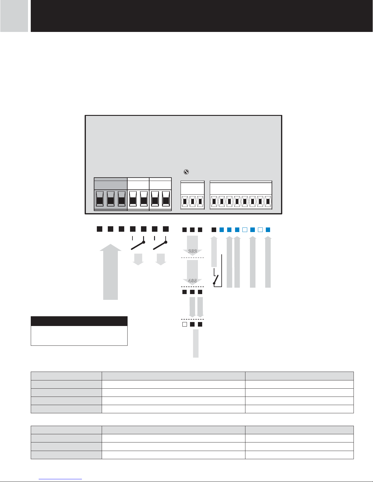
CONNECTION
Description Connection
Input A (< 30 V)
input signal < 43 V(absolute 60 V) GND + Input A(< 30 V)
Input A (< 300 V)
input signal < 300 V GND + Input A(< 300 V)
Resetting (< 30 V)
input signal < 43 V GND + Resetting (< 30 V)
Resetting (< 300 V)
input signal < 300 V GND + Resetting (< 300 V)
Function Description Control
Hold
Blocking display andinstrument outputs upon contact, bracket (no. 11/12)
Lock
Control keys blocking upon contact, bracket (no. 11/12)
Tare
Tare activation upon contact, bracket (no. 11/12)
+
11 12 13 14 15 16 17 18
GND
Reset (< 300 V)
INPUT A (< 300 V)
-
Excitation
Hold/Lock
+
-
54
L
N
POWER SUPPLY
E
123 567
8910
L2
L1
+
+
INPUT A (< 30 V)
232
485
GND
TxD
RxD
GND
Rx/Tx+
Rx/Tx-
GND
AO - I
AO - U
+
+
-
+
-
Reset (< 30 V)
+
3 INSTRUMENT CONNECTION
Grounding on bracket „E“ has to connected at
all times
!
INSTRUCTIONS FOR USE OM 652UC
|
7
Table of comparation levels
Input
Type of
input
Maximum input
voltage
(Level A, C)
Maximum comparation levels
L > H H > L
Input A
Resetting
(< 30 V)
NPN, Contact xxx 0,5 V 4,5 V
PNP 9,7 V 0,5 V 4,5 V
PNP 14,4 V 1,0 V 9,0 V
PNP 19,2 V 1,5 V 13,3 V
PNP 23,9 V 2,0 V 17,8 V
PNP 28,7 V 2,5 V 22,1 V
PNP 33,5 V 3,0 V 26,6 V
PNP 38,3 V 3,4 V 31,0 V
PNP 43,0 V 3,9 V 35,5 V
Input A
Resetting
(< 300 V)
NPN, Contact !!! prohibited !!!
PNP 84 V 4,9 V 39,8 V
PNP 128 V 9,2 V 78,0 V
PNP 170 V 13,6 V 117,8 V
PNP 211 V 17,8 V 156,0 V
PNP 253 V 22,3 V 195,8 V
PNP 295 V 26,5 V 234,1 V
PNP 301 V 30,9 V 273,9 V
3INSTRUMENT CONNECTION
8
|
INSTRUCTIONS FOR USE OM 652UC
SETTING PROFISETTING LIGHTSETTING USER
INSTRUMENT SETTING3
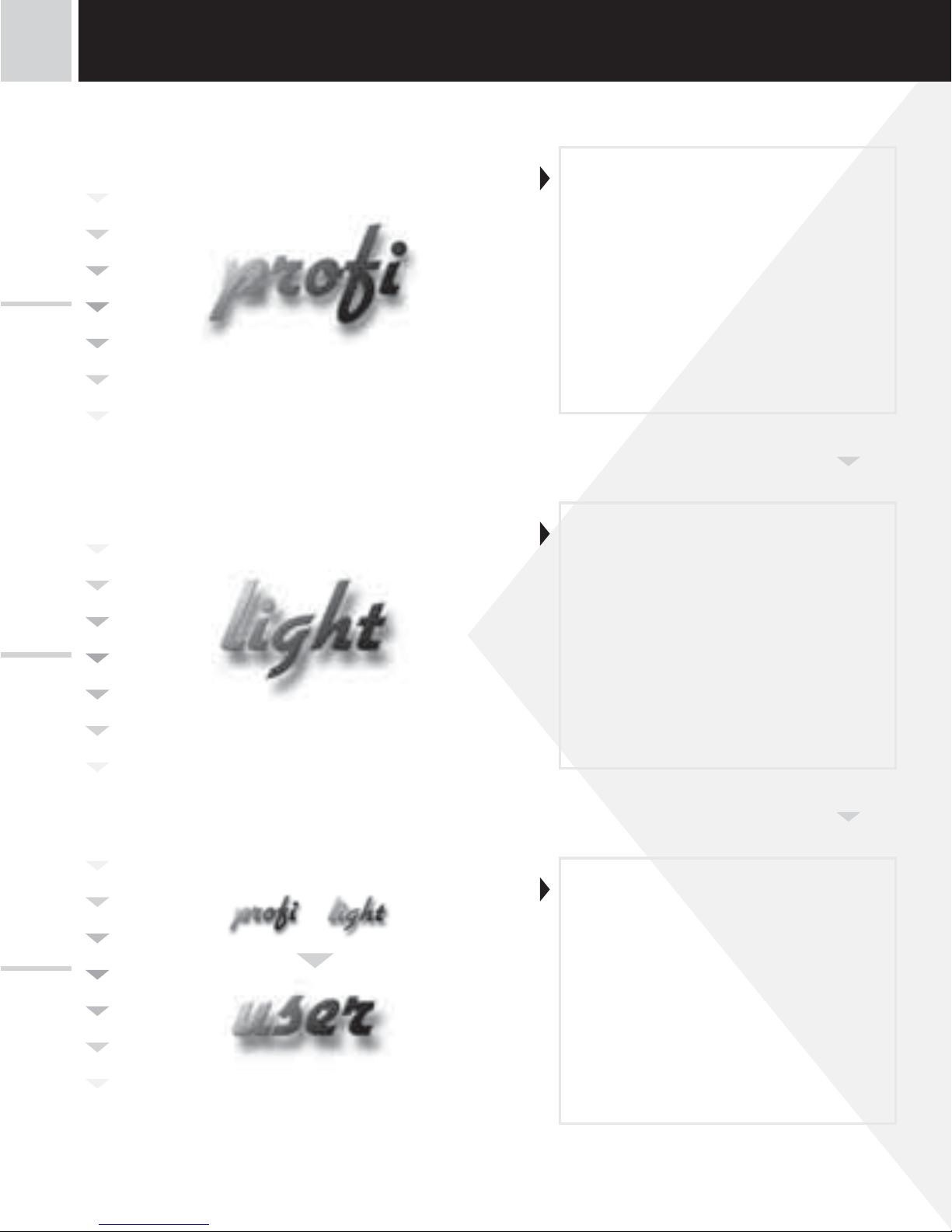
• For trained users
• Only items necessary for instrument
setting
• Access is password protected
• Possibility to arrange items of the
„User“ menu
• Linear menu structure
• For expert users
• Complete instrument menu
• Access is password protected
• Possibility to arrange items of the
„User“ menu
• Tree menu structure
• For user operation
• Menu items are set by the user
(Profi/Light) as per request
• Access is not password protected
• Optional menu structure either tree
(PROFI) or linear (LIGHT)

INSTRUCTIONS FOR USE OM 652UC
|
9
4.1 Setting
The instrument is set and controlled by five control keys located on the front panel. All programmable settings of the instrument
are performed in three adjusting modes:
LIGHT Simple programming menu
- contains solely items necessary for instrument setting and is protected by optional number code
PROFI Complete programming menu
- contains complete instrument menu and is protected by optional number code
USER User programming menu
- may contain arbitrary items selected from the programming menu (LIGHT/PROFI), which determine
the right (see or change)
- acces without password
All programmable parameters are stored in the EEPROM memory (they hold even after the instrument is switched off).
Complete instrument operation and setting may be performed via OM Link communication interface, which is a standard
equipment of all instruments.
The operation program is freely accessible (www.orbit.merret.cz) and the only requirement is the purchase of OML cable to connect the instrument to PC. It is manufactured in version RS 232 and USB and is compatible with all ORBIT MERRET instruments.
Another option for connection is with the aid of data output RS 232 or RS 485 (without the need of the OML cable).
3INSTRUMENT SETTING
10
|
INSTRUCTIONS FOR USE OM 652UC
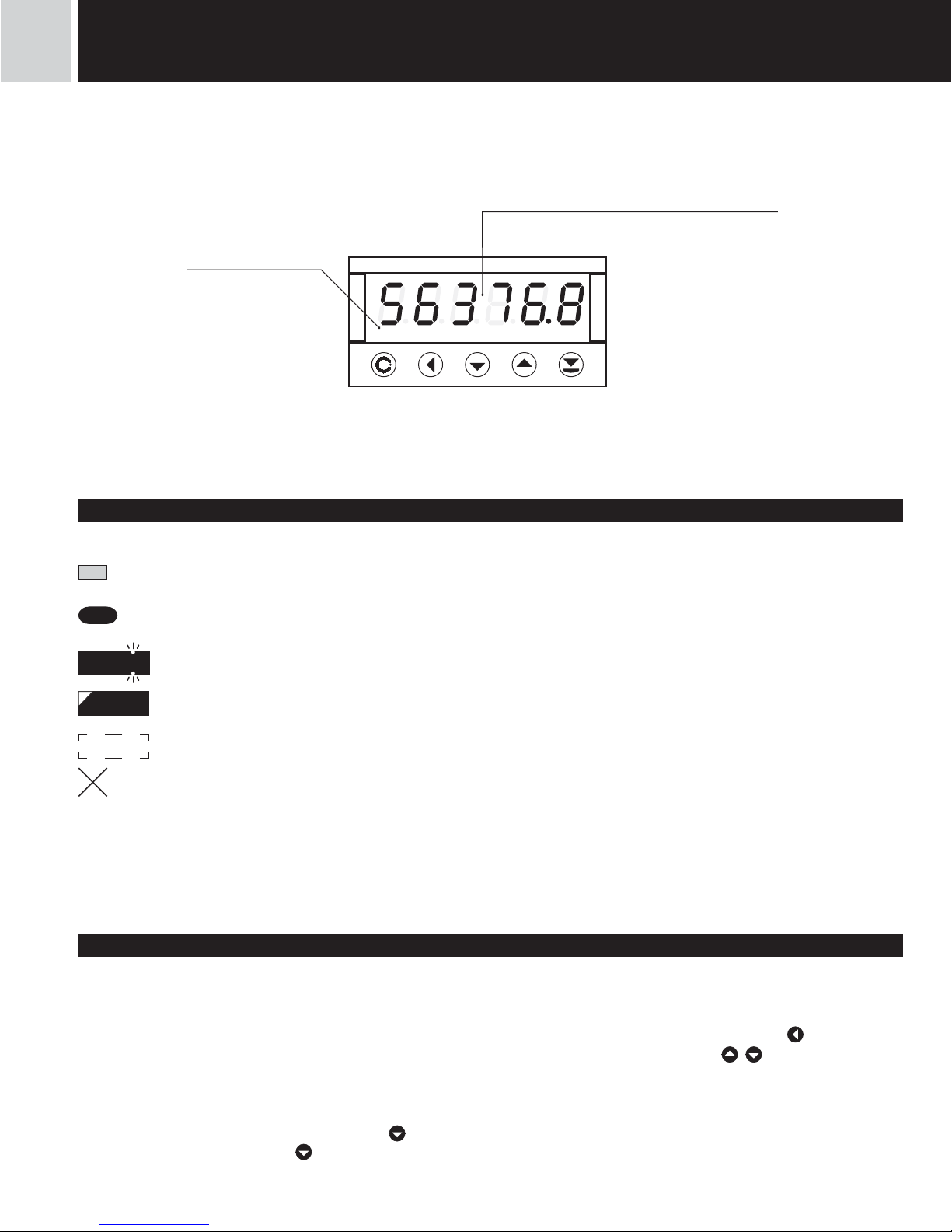
Setting and controlling the instrument is performed by means of 5 control keys located on the front panel. With the aid of
these keys it is possble to browse through the operation menu and to select and set required values.
Symbols used in the instructions
H
Indicates the setting for given type of instrument
DEF
values preset from manufacture
42
symbol indicates a flashing light (symbol)
MI N
inverted triangle indicates the item that can be placed in USER menu
CONECT.
broken line indicates a dynamic item, i.e. it is displayed only in particular selection/version
after pressing the key the set value will not be stored
after pressing the key the set value will be stored
30
continues on page 30
Setting the decimal point and the minus sign
DECIMAL POINT
Its selection in the menu, upon modification of the number to be adjusted it is performed by the control key with transition
beyond the highest decade, when the decimal point starts flashing . Positioning is performed by / .
THE MINUS SIGN
Setting the minus sign is performed by the key on higher decade. When editing the item substraction must be made from
the current number (e.g..: 013 >
, on class 100 > -87)
12
Relay status
ON the digit is lit
OFF the digit is not lit
OFF the digit is flashing
limits with restriction
(hysteresis, delay)
Measured value
4 INSTRUMENT SETTING
INSTRUCTIONS FOR USE OM 652UC
|
11
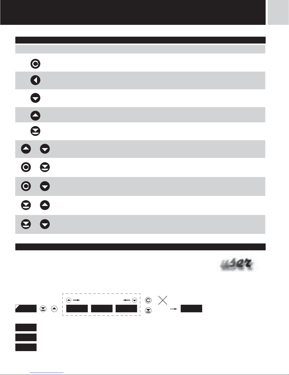
Control keys functions
Setting items into „USER“ menu
• in LIGHT or PROFI menu
• no items permitted in USER menu from manufacture
• on items marked by inverted triangle
NO
item will not be displayed in USER menu
YES
item will be displayed in USER menu with the option of setting
SHO
item will be solely displayed in USER menu
4INSTRUMENT SETTING
Key Measurement Menu Setting numbers/Selection
access into USER menu exit menu w/o saving
transition to next item w/o
saving
tare value return to previous level move to higher decade
cancel Tare move to previous item move down
cancel Tare move to next item move up
Tare confi rm selection setting/selection confi rmation
+
numeric value is set to zero
+
access into LIGHT/PROFI
menu
+
direct access into PROFI menu temporary (remains LIGHT)
+
confi guration of an item for
“USER” menu
+
determine the sequence of items
in “USER - LIGHT” menu
---
+
NO YES SHO
---
return to item
legend is flashing - current setting is displayed
12
|
INSTRUCTIONS FOR USE OM 652UC
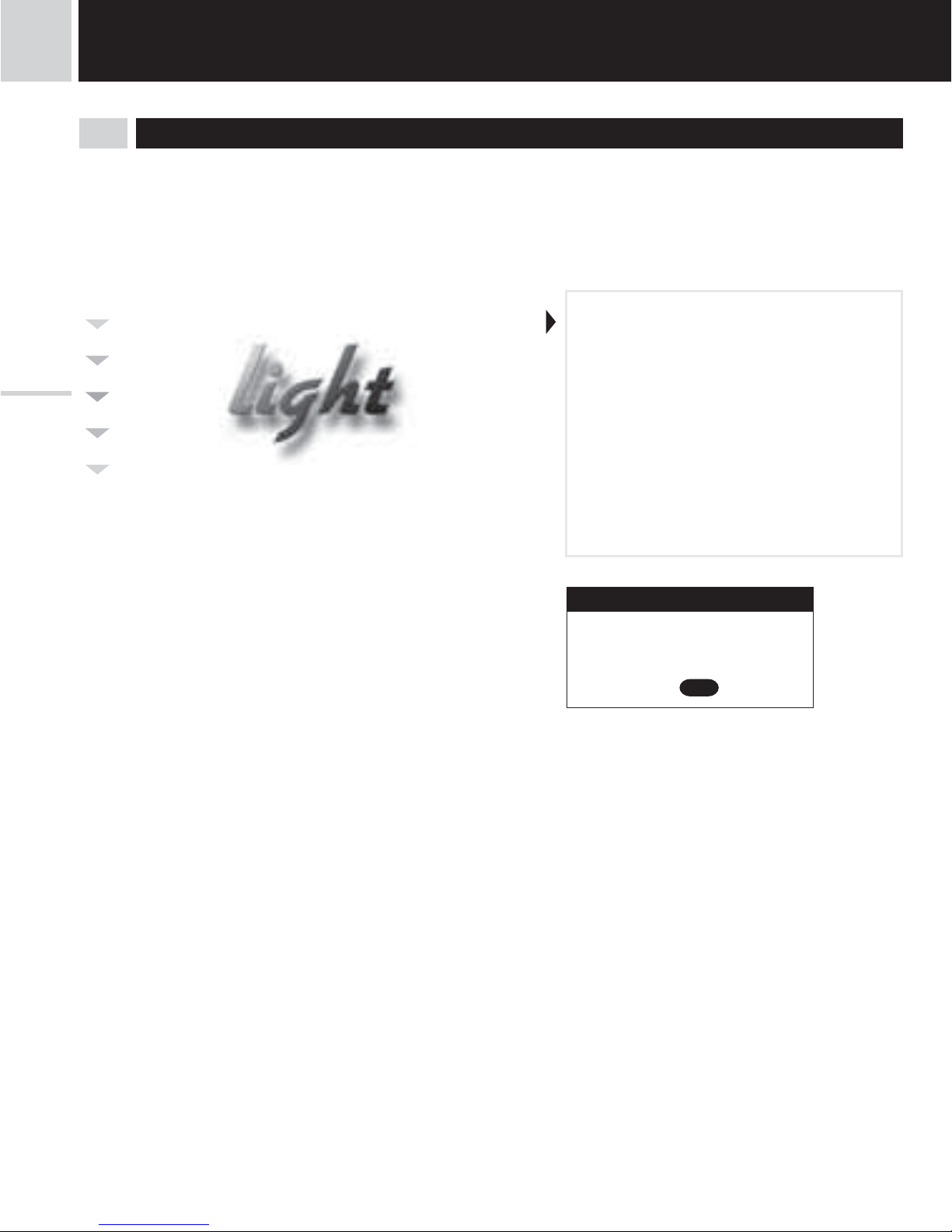
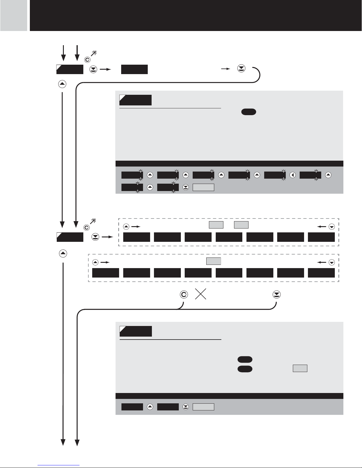
5.0 Setting “LIGHT”
LIGHT Simple programming menu
- contains only items necessary for instrument setting and is protected by optional numeral code
SETTING LIGHT
5 SETTING
lightlight
• For capable users
• Only items necessary for instrument
setting
• Password protected access
• Possibility to arrange items of the
„User“ menu
• Linear menu structure
Password “0”
Menu LIGHT
USR menu off
Setting the items
DEF
Preset from manufacture
INSTRUCTIONS FOR USE OM 652UC
|
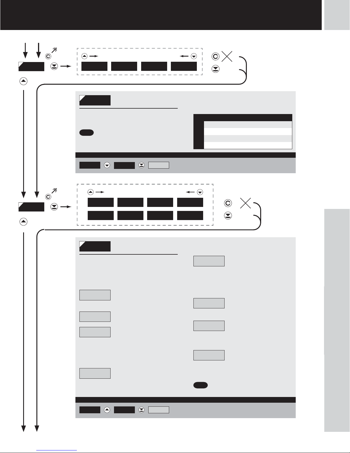
13
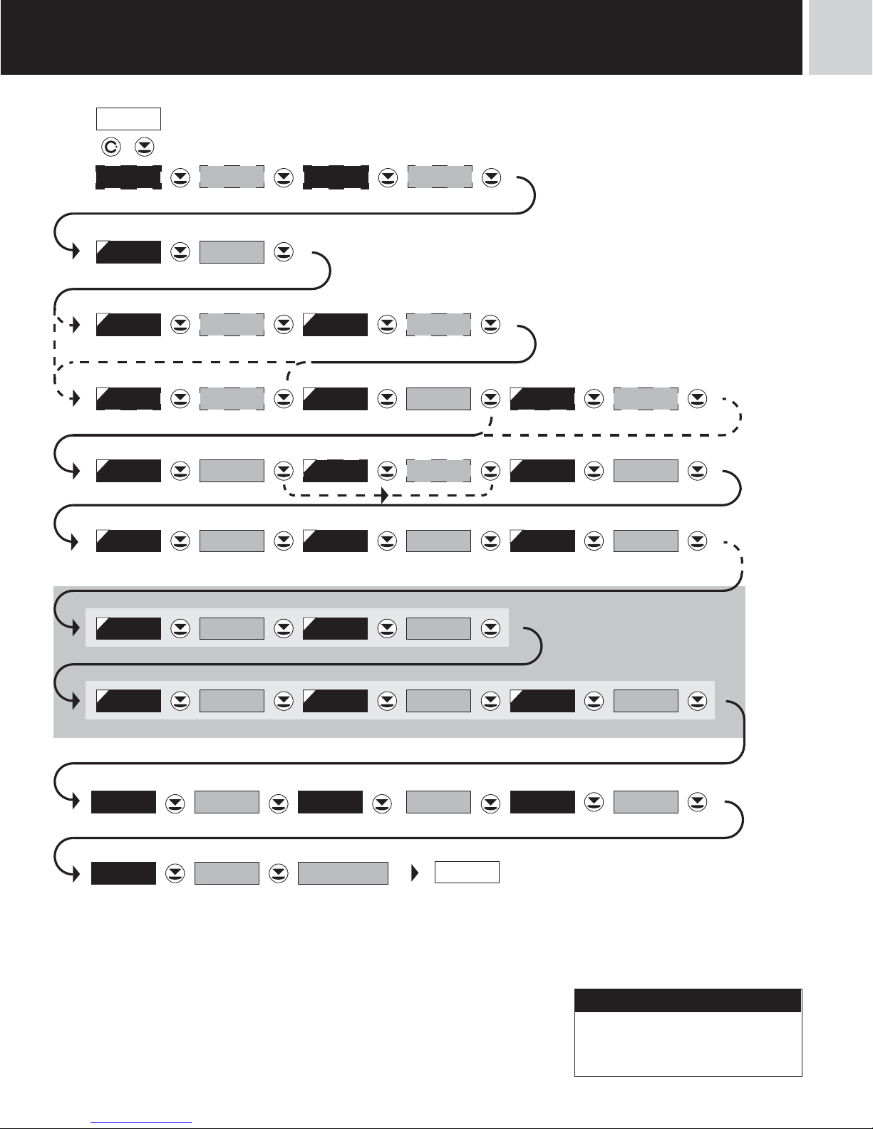
Return to previous measuring mode
TYP. A. O . MI N . A . O. MAX. A .O. 10004-20mA
LI M . L.1 25 LI M . L. 2 75
MENU LI G H T
IDENT.
142. 8
OM 652. . . .
N. PASS. 0FI R M . YES
YES
142. 8
PASSW.
0
+
FREQV .
MODE
OFFFI LTER NPN.CO N .TYPE A 10LEV ELA
NPN.CON .TYPE C 10LEV ELC 1SCALE
0OFFSET
SET V .
0
CLEA RM . STOPCONTAC.M. START
000000FORM . A1DI VI D .
5SETTING
lightlight
Option - Analog output
Option - Comparator
Menu type
Identifi cation
New password
Return to manufacture setting
Access code
Only for Mode > TIME and RTC
Upon delay exceeding 60 s the programming mode
is automatically discontinued and the instrument
itself restores the measuring mode
!

14
|
INSTRUCTIONS FOR USE OM 652UC
142. 8
PASS. 0
Entering access password
for access into the menu
PASS.
Access into instrument
menu
PAS = 0
- access into menu is unrestricted, after
releasing keys you automaticaly move to first
item of the menu
PAS > 0
- access into menu is protected ny numeric
code
Set “PASS.” = 42 Example
0 1 2 02 12
42
22
32 SET V.
SET V .
Setting initial value
- the function allows the user a single-time
setting of initial value of display projection
- the instrument is preset from manufacture
into “FREQU.” measuring mode and unless
another mode is set the item remains hidden
- if you need to set initial value for another
mode it is necessary to do so upon next
access to programming menu > after
change of measuring mode
- setting “SET V.” is a one-time operation
unlike the “OFFSET” option, i.e. after
resetting the display value is “0”, provided
there is no other value set in the “OFFSET”
item
DEF
= 0
SET V .
0
Setting initial value
The item „SET V.“ is not projected for measuring
mode „FREQU.“
!
Set “S ET V.” = 233 Example
0 1 2 3 03
33
13
23 MODE233133033
+
5 SETTING
lightlight
INSTRUCTIONS FOR USE OM 652UC
|
15
COUN t . FREQV .
MODE
Selection of instrument
measuring mode
- elementary selection of instrument type
DEF
= FREQU.
MODE
Menu Instrument mode
COUNT. Counter
FREQU. Frequencymeter
TIME Stopwatch/timer
RTC Stopwatch/backup timer
MODE
RTCTI M E
Selection of “COUNT.” mode Example
FILTE RFREQV .
COU Nt .
M. START
Selection of stopwatch/
timer control
- menu for time setting is accessible only in the
stopwatch/timer mode
CONTIN.
Stopwatch/timer is running
constantly if the instrument
is turned on
CONTAC.
Stopwatch/timer is running
upon contact making
EDGE
Stopwatch/timer is
controlled by the priming
signal edge
- time is set off by the edge (by the signal
passing across the comparing level) and
stopped by the next edge
RU n . ST.C.
Stopwatch/timer is
controlled and reset by the
edge of the priming signal
- time is set off by the edge (by the signal
passing across the comparing level) and
stopped by the next edge
C.RU n . ST.
Stopwatch/timer is
controlled and reset by the
edge of the priming signal
- time is set off by the edge (by the signal
passing across the comparing level) and
stopped by the next edge
CLR.RU N .
Stopwatch/timer is reset
and set off by the edge of
the priming signal
CL. RU .RE .
Stopwatch/timer is reset
and set off by the edge of
the priming signal, the cycle is repeated
with every other edge
RUN
Stopwatch/timer is only set
off by the edge
DEF
= COntAC.
M. START
CONTIN. CONTAC. EDGE RU N .ST.C.
C.RUN .ST. CLR.RU N CL.RU .RE . RU N
>
>
Selection of stopwatch control > EdGE Example
M. STOPCONTAC. EDGE
Only for measuring mode
TIME • RTC
5SETTING
lightlight
16
|
INSTRUCTIONS FOR USE OM 652UC
Only for measuring mode
TIME • RTC
Only for measuring mode
COUNT. • TIME • RTC
5 SETTING
lightlight
M. STOP
Selection of stopwatch
resetting
- menu of the resetting option is accessible
only in the stopwatch/timer regime
DEF
= CLEAR
CLEA R
Stopwatch/timer is reset
through input „Clear“
ST. CLR.
Stopwatch/timer is stopped
and reset through input
„Clear“
STOP
Stopwatch/timer is stopped
through input „Clear“
Selection of type of stopwatch resetting > St. CLr. Example
CLEAR ST. CLR. FILTE R
M. STOP
CLEA R ST. CLR. STOP
OFF 1000 100 40 5
FI LTER
Selection of digital filter
- digital filter may suppress unwanted
interfering impulses (e.g. relay backswings)
on the input signal. The set parameter gives
maximum possible frequency, which the
instrument processes w/o limitation
DEF
= OFF
FI LTER
Maximum input frequency 100 Hz > 100 Example
TYP E A .OFF 1000 100
When accessing upon contact and available
maximum input frequency we recommend using filter
!
INSTRUCTIONS FOR USE OM 652UC
|
17
5SETTING
lightlight
10
Setting input level
LEV EL .A
Setting input level for
Input A
- setting applies for Input A
- setting level (only for type PNP) of the
input voltage, the instrument subsequently
automatically selects divider and thus the
comparing levels
- range of setting 0…43 V(Input < 30 V)
- range of setting 43…300 V(Input < 300 V)
- table of comparing levels is on page 7
Setting the level = 34 V Example
10 11 12 13 14
34
14
24 TYP E C.
LEV EL .A
NPN.CON . PNP
TYP E A
Selection of type of input
- setting applies for Input A
DEF
= NPN.CON.
TYPE
Menu Type of input
NPN.CON. NPN or contact
PNP PNP
Selection of type of inpu t > NPN Example
LEV EL. ANPN.CO N.
TYP E A
Input levels (Level A) have to be set after this option
!

18
|
INSTRUCTIONS FOR USE OM 652UC
5 SETTING
lightlight
NPN.C PNP
TYP E C
Selection of type of input
- setting applies for resetting input
DEF
= NPN.CON.
TYPE
Menu Type of input
NPN.CON. NPN or contact
PNP PNP
Selection of type of inpu t > NPN Example
LEV EL. CNPN.CO N.
TYP E C
Input levels (Level C) have to be set after this option
!
10
Setting input level
LEV EL .C
Setting input level for
resetting input
- setting the level (only for PNP type) of
input voltage, the instrument subsequently
automatically selects divider and thus the
comparing levels
- range of setting 0…43 V(Input < 30 V)
- range of setting 43…300 V(Input < 300 V)
- table of comparing levels is on page 7
Setting levels = 34 V Example
10 11 12 13 14
34
14
24 SCALE
LEV EL .C
INSTRUCTIONS FOR USE OM 652UC
|
19
5SETTING
lightlight
1
Setting division constant
DI VI D .
Setting division constant
- calibration constant is for calculation of the
input value to required display value
- range: -0,00001...999999
-
DEF
= 1
Division constant = 22 Example
1 2 02 12 22 OFFSET
DI VI D .
1
Setting multiplyingconstant
SCALE
Setting multiplying
constant
- calibration constant serves for calculation of
the input value to required display value
- by entering minus value direction of the
calculation is changed, i.e. we count down
- range: -0,00001...999999
-
DEF
= 1
Cali bration consta nt = 3,12 Example
1 2 02 12 012 112
212
DI VI D .
312 312 .0312 31 . 2 3 .12
SCALE
20
|
INSTRUCTIONS FOR USE OM 652UC
5 SETTING
lightlight
0
Setting PRESET
OFFSET
Setting additive constant
- PRESET
- offset of the measuring by a set value, which
shall be loaded always upon instrument
resetting
- range: -99999...999999
(+ time formats)
-
DEF
= 0
Setting „PRESE T“ = 24 Example
0 1 2 3 4
24
04
14 FORM . A
OFFSET
FORM . A
000000 00000. o 0000. oo 000. ooo 00. oooo 0. ooooo FLO A . P.
FORM . A
Selection of projection
format
- instrument enables classical projection of
number with fixed position of decimal point
as well as projection with floating allowing
fo projection of number in its most precise
form „FLOA. P.“
- for measuring modes „TIME“ and „RTC“
special time formats are preset
DEF
= 000000
DEF
= HH.MM.SS
H
Projection of DP on display > 00000.o Example
LI M . L. 1
* subsequent menu item depends on instrument equipment
000000 00000. o
99. MM.SS HH. MM HHHH. MM MMMM.SS MM.SS.CC 99.SS . CC H . MM.SS.CHH. MM. SS
F C
H

INSTRUCTIONS FOR USE OM 652UC
|
21
5SETTING
lightlight

22
|
INSTRUCTIONS FOR USE OM 652UC
5 SETTING
lightlight
LI M . L. 2
LI M . L.1
25
LI M . L.1
Setting the boundary for
limit 1
- range of the setting is -99999…999999
(+ time formats)
- presetting “Hysteresis”=0 “Delay”=0
- contingent change of hysteresis or offset
of the switch-on may be performed in the
PROFI menu
DEF
= 25
Setting the boundary
for limit 1
LI M . L. 2
Setting the boundary for
limit 2
- range of the setting is -99999…999999
(+ time formats)
- presetting “Hysteresis”=0 “Delay”=0
- contingent change of hysteresis or offset
of the switch-on may be performed in the
PROFI menu
DEF
= 75
75
Setting the boundary
for limit 2
Setting limit 2 > L 2 = 230 Example
100 100 130 130 120 110
230 MENU
* following item of the menu depends on instrument equipment, provided it has an analog
output the following item is „Type“
Setting limit 1 > L 1 = 30 Example
25 26 20 29 28 27
20 30 LI M . L .2
Items for “Limits” and “Analog output” are accessible only if the instrument contains them.
!
Only with option > Dual Comparator

INSTRUCTIONS FOR USE OM 652UC
|
23
5SETTING
lightlight
MAX. A .O.
Assigning the display
value to the end of the
AO range
- range of the setting is -99999…999999
DEF
= 100
MI N . A . O.
Assigning the display
value to the beginning of
the AO range
- range of the setting is -99999…999999
DEF
= 0
TYP. A. O .
Setting the type of analog
output
Menu Range Description
0-20nA 0…20 mA
Er 4-20 4…20 mA with indication of error statement (<3,6 mA)
4-20nA 4…20 mA
0-5nA 0…5 mA
0-2 u 0…2 V
0-5 u 0…5 V
0-10 u 0…10 V
DEF
= E 4
Display value for the beginning o f the AO range > M In.A.O. = 0 Example
MAX. A .O.
TY .A. O .
Type of analog output - 0...10 V > tY.A.O. = U 10 Example
4-20m A 0-2 V0-5m A 0-10 V 0-5 V MI N . A .O .
0-20mA Er4-20 4-20m A 0-5mA 0-2 V 0-5 V 0-10 V
0
Assigning the display
value to the beginning of
the AO range
0 MAX. A .O .
100
Assigning the display
value to the end of the
AO range
MI N . A . O.
Display value for the end of the AO range > MAX. A.O. = 120 Příklad
100 100 120 110 MENU
Only with option > Analog output

24
|
INSTRUCTIONS FOR USE OM 652UC
5 SETTING
lightlight
Menu LIGHT > M ENU = LIGHT Example
FI R M .
Restoration of the
instrument manufacture
setting
- in case of incorrect setting or calibration it
is possible to return to manufacture setting.
Prior execution of the changes you will be
asked to confirm your selection (YES)
- reading the manufacture calibration and
original setting of items in the menu
MENU
MENU
Setting the menu type
LIGHT/PROFI
LIGHT > LIGHT menu, a simple menu,
which contains only items necessary for
instrument setting
> linear structure of the menu
PROFI > PROFI menu, a complete menu for
entire instrument setting
> tree structure of the menu
DEF
= LIGHT
LIGHT FI R M . .
LI G H T PROFI
FI R M .
Restoration of manufacture setting > FIRM . Example
FI R M . . n . PASS.
YES
YES
Do not perform restoration of user setting (USER)
prior to its saving in Profi menu
!

INSTRUCTIONS FOR USE OM 652UC
|
25
5SETTING
lightlight
0
Setting new access
password
n . PASS.
n . PASS.
Setting new access
password
- access password for LIGHT/PROFI menu
- range of the numeral code 0…9999
- when setting password to “0000” the
access into LIGHT/PROFI menu is accessible
without call for entering it
- in case of loss of password universal
password “8177” may be used
DEF
= 0
IDENT.
IDENT.
SW version of the
instrument
- the display shows the type identification of
the instrument, SW number, SW version and
current input setting (Mode)
- if the SW version reads a letter on the first
position, then it is a customer SW
- after the identification is completed the
menu automatically quits the display and
measuring mode is restored
YES
OM 652 61 - 001
setting the input typeSW number SW version
FREQV .
Instrument type
142. 8
Return to measuring mode
New password - 341 > n.PASS. = 341 Example
0
IDENT.
1 01 11 21 31
41 041 341 241 141

26
|
INSTRUCTIONS FOR USE OM 652UC
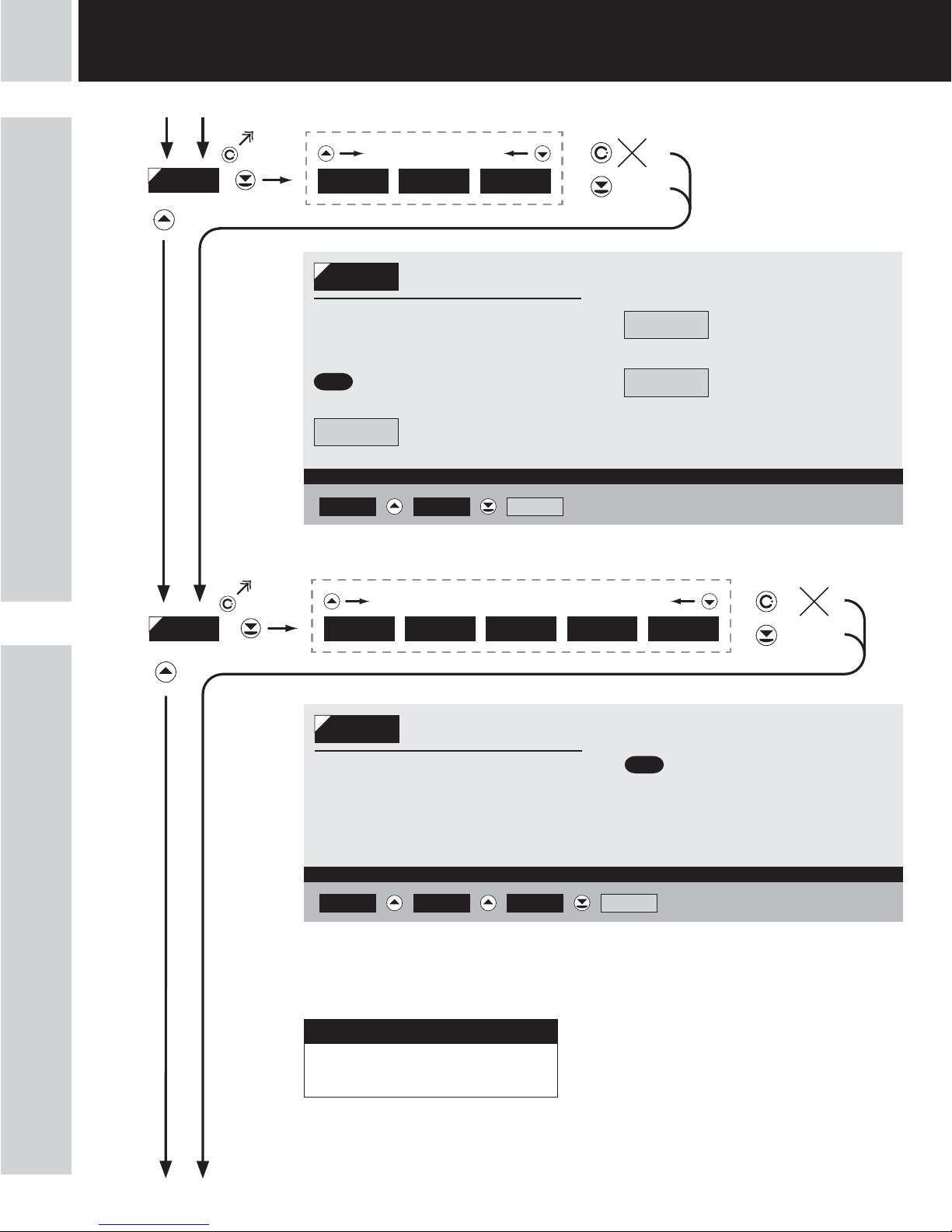
6 SETTING
profi profi
6.0 Setting “PROFI”
PROFI Complete programming menu
• contains complete instrument menu and is protected by optional number code
• designed for expert users
• preset from manufacture is menu LIGHT
Switching over to “PROFI” menu
+
• temporary switch-over to PROFI menu, which is suitable to edit a few items
• after quitting PROFI menu the instrument automatically switches to LIGHT menu
• access is password protected (if it was not set under item N. PASS. =0)
+ • access into LIGHT menu and transition to item „MENU“ with subsequent selection of „PROFI“
and confirmation
• after re-entering the menu the PROFI type is active
• access is password protected (if it was not set under item N. PASS. =0)
• For expert users
• Complete instrument menu
• Access is password protected
• Possibility to arrange items of the
„User“ menu
• Tree menu structure
SETTING PROFI

INSTRUCTIONS FOR USE OM 652UC
|
27
6SETTING
profi profi

28
|
INSTRUCTIONS FOR USE OM 652UC
6 SETTING
profi profi
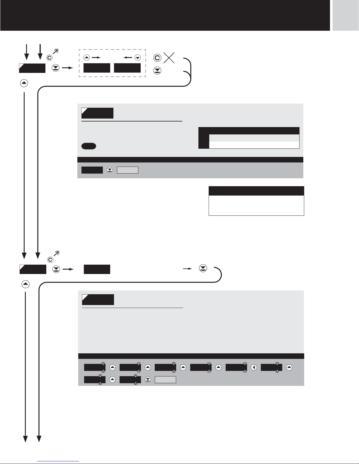
6.1 Setting “PROFI” - INPUT
6.1.1 Resetting internal values
INPUT
SERVIC.
OUTPUT
CHANNE.
CLEA R
EXT . IN.
CONFIG
KEYS
The basic instrument parameters are set
in this menu
CLEA R
Resetting internal values
CONFIG
Primary instrument setting
EXT . IN.
Setting the external input
function
KEYS
Setting the ENTER key
function
INPUT
SERVIC.
OUTPUT
CHANNE.
CLEAR
EXT . IN.
CONFIG
KEYS
CL. TA R.
CL. CN T .
CLEA R
Resetting internal values
CL. CN T .
Counter resetting
CL. TA R.
Tare resetting

INSTRUCTIONS FOR USE OM 652UC
|
29
6.1.2 Instrument configurtion
6.1.2a Setting the initial value
C
H
M. TI M E
MODE
INPUT
SERVIC.
OUTPUT
CHANNE.
EXT . IN.
CONFIG
KEYS
M. START
M. STOP
TYP E A .
FI LTER
LEV EL .C
TYP E C .
LEV EL .A
POLAR.
BACKUP
SET. V.CLEA R
CONFIG
Primary instrument
setting
SET. V.
Setting the initial value
MODE
Setting the instrument
measuring mode
M. TI M E
Setting the time base
M. START
Setting the stopwatch
control
M. STOP
Setting stopwatch
resetting
FI LTER
Setting the input filtration
constant
TYP E -
Setting the type of input
LEV EL . -
Setting the input level
POLAR.
Selection of active level/
edge
BACKUP
Setting data backup/
time
INPUT
SERVIC.
OUTPUT
CHANNE.
CLEA R
EXT . IN.
CONFIG
SET V.
KEYS
M. TI M E
MODE
M. STOP
M. START
TYP E A
FI LTER
LEV EL .C
TYP E C
LEV EL .A
POLAR.
BACKUP
0
SET V .
Setting initial value
- function allows the user a one-time setting
of the display initial value
6SETTING
profi profi

30
|
INSTRUCTIONS FOR USE OM 652UC
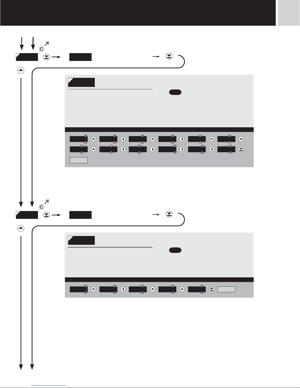
6.1.2b Selection of measuring mode
6.1.2c Selection of measuring period/time base
CLEA RINPUT
SERVIC.
OUTPUT.
CHANNE.
EXT .IN.
CONFIG
COUNT.
FREQV .
KEYS
RTC
TI M E
DEF
M. START
M. STOP
M. TI M E
MODE
TYP E A
LEV EL .C
TYP E C
LEV EL .A
FI LTER
BACKUP
POLAR.
SET. v .
MODE
Selection of instrument
measuring mode
COUNT.
Mode „Counter“
- counts on input A
FREQU .
Mode „Frequencymeter“
- measures frequency on input A
TI M E
Mode „Stopwatch/
timer“
RTC
Mode „Stopwatch/
timer“ with RTC backup
- not in standard equipment
DEF
0.5
5. 0
1. 0
10. 0
INPUT
SERVIC.
OUTPUT.
CHANNE.
EXT .IN.
CONFIG
KEYS
M. TIME
MODE
M. START
M. STOP
TYP E A
LEV EL .C
TYP E C
LEV EL .A
FI LTER
BACKUP
POLAR.
SET. v .CLEAR
M. TI M E
Selection of measuring
period/time base
- if you set measuring period e.g. for 1 s,
the measuring runs approximtely from
1 sto 2 s(1 s+ maximum one cycle of
measured signal). If no signal arrives
within 2 sit is taken that the signal has
zero frequency
- range of setting of the time base
is 0,5 sto 10 s
- in the „RTC“ regime with data projection
the set time defines the cycle of switching
between time/date, min. is 5 s, datue is
displayed for approx. 2,5 s
6 SETTING
profi profi

INSTRUCTIONS FOR USE OM 652UC
|
31
6SETTING
profi profi
6.1.2d Selection of stopwatch/timer control
H
CLEA R
RUN
CL. RU .RE .
CLR.RU N .
MODE
INPUT
SERVIC.
OUTPUT.
CHANNE.
EXT .IN.
CONFIG
KEYS
TYP E A
LEV EL .C
TYP E C
LEV EL .A
FI LTER
BACKUP
POLAR.
SET. V.
M. START
M. STOP
DEF
CONTIN.
CONTAC.
EDGE
RUN .ST. C.
C.RUN .ST.
M. TI M E
M. START
Selection of stopwatch/
timer control
- time setting menu is accessible only in the
stopwatch/timer regime
CONTIN.
Stopwatch/timer is
running constantly if the
instrument is turned on
CONTAC.
Stopwatch/timer is
running upon contact
making
EDGE
Stopwatch/timer is
controlled by the priming
signal edge
- time is set off by the edge (by the signal
passing across the comparing level) and
stopped by the next edge
RU n . ST.C.
Stopwatch/timer is
controlled and reset by
the edge of the priming signal
- time is set off by the edge (by the signal
passing across the comparing level) and
stopped by the next edge
C.RU n . ST.
Stopwatch/timer is
controlled and reset by
the edge of the priming signal
- time is set off by the edge (by the signal
passing across the comparing level) and
stopped by the next edge
CLR.RU N .
Stopwatch/timer is reset
and set off by the edge
of the priming signal
CL. RU .RE .
Stopwatch/timer is
reset and set off by the
edge of the priming signal, the cycle is
repeated with every other edge
RUN
Stopwatch/timer is only
set off by the edge

32
|
INSTRUCTIONS FOR USE OM 652UC
6 SETTING
profi profi
142. 8
+
PASS. 0
INPUT CHANNE.
SET. A
SCALE 1
FORM . A
000000 00000.o 0.ooooo FLOA. P.
FI LTER MOD. F. A
CON . F.A 0
NO EXPON.. ROUND.
CLEAR
CL. CNT. CL. TAR ...
CONFIG DI VI D . 1
EXT . IN. EX T. 1
OFF LOCK. K. HOLD TARE CLEAR CLR. ST.
KEYS ALL
NO YES
M. TI M E
0.5 1.0 5.0 10.0
MODE
COUNT. FREQV.. TIME RTC
FI LTER
OFF 1000 100 40 5
LEV EL. A
TYP E A .
NPN.CON. PNP
LEV EL. C
TYP E C.
NPN.CON. PNP
POLAR.
Lo \ HI /
10
10
BACKUP
YES NO
OFFSET 0
Programming schem
HH.MM.SS 99.MM.SS MM.SS HHHH.MM H.MM.S
S
SET V .
0
M. STOP
CLEAR ST. CLR... STOP
M. START
CONTIN. CONTAC... EDGE RUN
BACKUP
NO VALUE TIME

INSTRUCTIONS FOR USE OM 652UC
|
33
6SETTING
profi profi
IDENT. OM 652UC. . . .
SERVIC.
OUTPUT
LI M I T S LI M . 1 .
RESTO R.
SAVE
MENU
LIGHT PROFI
TI M . L.1 0
HYS. L.1 0
LI M . L.1 25
LI M . 2.
TI M . L.2 0
HYS. L. 2 0
LI M . L. 2 75
TYP. L.2
CLOSE OPEn
USER
FI R M .
MOD. L.1
HYSTER. C.-PULS.
TYP. L.1
CLOSE OPEN
DI S P.
100MAX. A .O .
0MI N . A .O .
AN. OUT. TYP. A. O .
0-20mA Er4-20 4-20mA 0-5mA 0-2 V 0-5 V 0-10 V
ADDR. 0
DATA BAUD
300 600 1200 2400 4800 9600 19200 38400 57600 115200 230400
BRIGHT.
25% 50% 75% 100%
0N . PASS.
MOD. L.2
HYSTER. ON RUN
Upon delay exceeding 60 s the programming mode
is automatically discontinued and the instrument
itself restores the measuring mode
!

34
|
INSTRUCTIONS FOR USE OM 652UC
6 SETTING
profi profi
6.1.2e Selection of stopwatch/timer resetting
H
6.1.2f Selection of input filter parameters
C
H
MODE
INPUT
SERVIC.
OUTPUT.
CHANNE.
EXT .IN.
CONFIG
KEYS
TYP E A
LEV EL .C
TYP E C
LEV EL .A
FI LTER
BACKUP
POLAR.
SET. V.
M. START
M. STOP
M. TI M E
DEF
CLEA R
ST. CLR.
ST. CLR.
CLEA R
M. STOP
Selection of stopwatch
resetting
- menu of the resetting option is accessible
only in the stopwatch/timer regime
CLEA R
Stopwatch/timer is reset
through input „Clear“
ST. CLR.
Stopwatch/timer is
stopped and reset
through input „Clear“
STOP
Stopwatch/timer is
stopped through input
„Clear“
INPUT
SERVIC.
OUTPUT.
CHANNE.
EXT .IN.
CONFIG
KEYS
DEF
OFF
1000
5
40
100
MODE
TYP E A
LEV EL .C
TYP E C
LEV EL .A
M. STOP
BACKUP
POLAR.
M. START
FI LTER
M. TI M E
SET. v .CLEAR
FI LTER
Selection of digital input
filter
- digital filter may suppress unwanted
interfering impulses (e.g. relay
backswings) on the input signal. The
set parameter gives maximum possible
frequency (Hz) of the instrument, which
the instrument w/o limitation
When accessing upon contact and available
maximum input frequency we recommend using filter
!

INSTRUCTIONS FOR USE OM 652UC
|
35
6.1.2g Selection of the type of input
6.1.2h Setting input level
INPUT
SERVIC.
OUTPUT.
CHANNE.
EXT .IN.
CONFIG
KEYS
DEF
NPN.CON
PNPMODE
LEV EL .C
TYP E C
LEV EL .A
M. STOP
BACKUP
POLAR.
M. START
M. TI M E
FI LTER
TYP E A
SET. v .CLEAR
TYP E A
Selection of type of input
- setting applies for Input A
NPN.CON
Type of input NPN and
upon contact
PNP
Type of input PNP
Input levels (Level A) must be set after this selection
!
INPUT
SERVIC.
OUTPUT.
CHANNE.
EXT .IN.
CONFIG
KEYS
10
MODE
LEV EL .C
TYP E C
M. STOP
BACKUP
POLAR.
M. START
M. TI M E
FI LTER
TYP E A
LEV EL .A
SET. v .CLEAR
LEV EL .A
Setting input level
- setting applies for Input A
- setting level (only for type PNP) of the
input voltage, the instrument subsequently
automatically selects divider and thus
comparing levels
- range of setting 0…43 V
(Input A< 30 V, bracket No. 13)
(Input C < 30 V, bracket No. 14)
- range of setting 43…300 V
(Input A<300 V, bracket No. 18)
(Input C <300 V, bracket No. 16)
- table of comparing levels is on page 7
6SETTING
profi profi
Nastavení pro vstup Nulovani (type C) je shodné s
nastavením Vstupu A
!
Nastavení pro vstup Nulovani (Level. C) je shodné s
nastavením Vstupu A
!
Setting for input Resetting (type C) is identical with
setting for Input A
!
Setting for input Resetting (Level. C) is identical with
setting for Input A
!

36
|
INSTRUCTIONS FOR USE OM 652UC
6.1.2i Selection of active level or edge
6.1.2j Selection of display status backup
INPUT
SERVIC.
OUTPUT.
CHANNE.
EXT .IN.
CONFIG
KEYS
DEF
Lo \
Hi /MODE
TYP E C
M. STOP
LEV EL .C
M. START
M. TI M E
FI LTER
TYP E A
BACKUP
POLAR.
LEV EL .A
SET. v .CLEAR
POLAR.
Selection of active level
or edge
Lo \
Active upon change of
declining edge Lo >Hi
- upon entering the contact > active on
switch-on
Hi /
Active upon change of
entering edge Hi > Lo
- upon entering the contact > active on
switch-off
INPUT
SERVIC.
OUTPUT.
CHANNE.
EXT .IN.
CONFIG
KEYS
DEF
NO
YESMODE
M. TI M E
TYP E C
LEV EL .C
FI LTER
TYP E A
POLAR.
BACKUP
LEV EL .A
SET. V.CLEAR
BACKUP
Selection of display
status backup
- setting display value restoration after
power failure or instrument switch-off
NO
After switch-on the
instrument loads the
display status from the memory
YES
Instrument resets itself
after switch-on
6 SETTING
profi profi

INSTRUCTIONS FOR USE OM 652UC
|
37
6.1.2k Setting the display status backup
H
6.1.3 External input function selection
INPUT
SERVIC.
OUTPUT.
CHANNE.
EXT .IN.
CONFIG
KEYS
TI M E
VALUE
NO
DEF
MODE
TYP E C
M. STOP
LEV EL .C
M. START
M. TI M E
FI LTER
TYP E A
POLAR.
BACKUP
LEV EL .A
SET. V.CLEAR
BACKUP
Selection of display
status backup
- time setting menu is accessible only in the
stopwatch/timer regime
- setting display value restoration after
power failure or instrument switch-off
NO
Instrument resets itself
after every switch-on
VALUE
After switch-on the
instrument loads the
display status from the memory
TI M E
Instrument downloads
„running“ time fromRTC
- item accessible only with extension „Time
backup“
INPUT
SERVIC.
OUTPUT
CHANNE.
CLEA R
CONFIG
KEYS
OFF
LOCK. K.
DEF
HOLD
EXT. IN.
EXT. 1
TARE
CLR. ST.
CLEA R
EXT . IN.
External input function
selection
OFF
Input is off
LOCK. K.
Auxiliary input governs
the „LOCK“ function
- the input governs the blocking of control
keys on front panel
HOLD
Auxiliary input governs
the „HOLD“ function
- the input governs the HOLD function,
which blocks all instrument functions
TARE
Auxiliary input governs
the „TARE“ function
- the TARE function is activated through the
input, only in the “Frequency” mode
CLEA R
Auxiliary input governs
the „Clear“ function
- stopwatch/counter is cleared (preset)
through the input
CLR. St.
Auxiliary input governs
the „Clear“ function
- stopwatch/counter is cleared (preset)
through the input, Stopwatcg stops
altogether
6SETTING
profi profi

38
|
INSTRUCTIONS FOR USE OM 652UC
6.1.4 Optional accessory functions of the keys
INPUT
SERVIC.
OUTPUT
CHANNE.
CLEA R
EXT. IN.
CONFIG
YES
NO
DEF
KEYS
ALL
ALL
Assigning accessory
functions of control keys
- owing to limited space in the instrument’s
memory it is not feasible to set the keys’
functions one by one
YES
Accessory functions
are on
Counter Frequency Stopwatch
- Resetting tare Resetting
- Resetting tare Display hold
- Tare projection Start
Resetting Tare Stop
NO
Accessory functions
are off
6 SETTING
profi profi
Control keys functions are described on page 11
!

INSTRUCTIONS FOR USE OM 652UC
|
39
6SETTING
profi profi

40
|
INSTRUCTIONS FOR USE OM 652UC
6.2 Setting “PROFI” - CHANNEL
6.2.1a Setting multiplying constant
6.2.1b Setting division constant
INPUT
SERVIC.
OUTPUT
CHANNE.
SET. A
FORM . A
FILTER
CHAN . A
In this menu the instrument input parameters are set
SET. A
Setting calibration
constant
FI LTER
Setting the digital filters
FORM . A
Selection of projection
format
INPUT
SERVIC.
OUTPUT.
CHANNE.
SET. A
FORM . A
FILTER
CHAN . A SCALE
OFFSET
DIVID.
1
SCALE
Setting multiplying
constant
- multiplying constant serves for calculation
of input value to required display value
- by entering minus value the direction
of calculation is changed, i.e. we count
down
- range: -0,00001...999999
-
DEF
= 1
INPUT
SERVIC.
OUTPUT.
CHANNE.
SET. A
FORM . A
FILTER
CHAN . A
OFFSET
DI VI D .
SCALE 1
DI VI D
Setting division constant
- division constant serves for calculation of
input value to required display value
- range: 0,00001...999999
-
DEF
= 1
6 SETTING
profi profi
If non-zero value is set in the “TIME” or “RTC” mode
in the “OFFSET” item, it applies that the multiplying
constant “SCALE” is negative
!
H

INSTRUCTIONS FOR USE OM 652UC
|
41
6.2.1c Setting additive constant - PRESET
6.2.2 Setting the digital filters
INPUT
SERVIC.
OUTPUT.
CHANNE.
SET. A
FORM . A
FILTER
CHAN . A
DIVID.
OFFSET
SCALE 0
OFFSET
Setting PRESET constant
- offset of the measuring by a set value,
which shall be loaded always upon
instrument resetting
- range: -99999...999999
-
DEF
= 0
MOD. F.A.INPUT
SERVIC.
OUTPUT.
CHANNE.
SET. A
FORM . A
FILTER
CHAN . A NO
EXPOn.
ROUND.
CON . F.A.
MODE
Setting the digital filters
CONS t .
Setting the constant
- this menu item is always displayed after
selection of a particular type of filter
-
DEF
= 2
NO
Filters are switched off
EXP ON .
Selection of exponential
filter
- calculation of value from the number of
measurements selected in„CONST“
ROUND.
Selection of value
round-up
- it is set by …arbitrary number, which
determines the projection step
(e.g.: “Con. F.A.”=2,5 > display 0,
2.5, 5,...)
6SETTING
profi profi
If non-zero value is set in the “TIME” or “RTC” mode
in the “OFFSET” item, it applies that the multiplying
constant “SCALE” is negative
!
H

42
|
INSTRUCTIONS FOR USE OM 652UC
6.2.3 Selection of projection format
FORM . A
H
DEF
000000
00000. 0
0000. 00
000. 000
00. 0000
FLOA . P.
HH. MM.SS
H. MM.SS . C
99. SS .CC
MMMM.SS
HHHH. MM
HH. MM
DEF
INPUT
SERVIC.
OUTPUT.
CHANNE.
SET.In
FILTER
CHAN . A
0. 00000
99. MM.SS
MM.SS.CC
FORM . A
Selection of projection
format
- the instrument enables projection of
number withdecade positioning of
decimal point
- for projection of time there are also other
projection forms available
6 SETTING
profi profi
In mode “TIME” or “RTC” the time base is preset
according to projection format
in seconds > 000000…0.00000, Floa.P.,
HH.MM.SS, 99.MM.SS, MMMM.SS
in minutes > HH.MM, HHHH.MM
in tenths of seconds > H.MM.SS.C
in hundredths of seconds > MM.SS.CC, 99.SS.CC
!
H

INSTRUCTIONS FOR USE OM 652UC
|
43
6SETTING
profi profi

44
|
INSTRUCTIONS FOR USE OM 652UC
6.3 Setting „PROFI“ - OUTPUTS
6.3.1a Selection of mode of output L 1
6.3.1b Selection of mode of output L 2
CHANNE.
SERVIC.
OUTPUT.
LI M I T S
AN. OUT.
DATA
DI S P .
INPUT
It is possible to set the parameters
of the instrument output signals in
this menu
LI M I T S
Setting the type and the
switching of limits
DATA
Setting the type and
the parameters ot data
output
AN. OUT.
Setting the type and
parameters of analog
output
DI S P .
Setting the display
brightness
INPUT
SERVIC.
OUTPUT
CHANNE.
LIMITS
AN. OUT.
DATA
DI S P .
LIM. 1
LI M . 2
HYSTER.
C. -P U LS .
DEF
HYS. L.1
LI M . L.1
TI M . L.1
MOD. L.1
TYP. L.1
MOD. L.1
Mode of limit 1
HYSTER.
Standard mode - limit,
hysteresis and delay
C. -P U LS .
Automatic clearing of
counter to preset value
and generate an impulse of the length
set in “TIM.L.1”
Setting is available only for LIM 1
!
INPUT
SERVIC.
OUTPUT
CHANNE.
LIMITS
AN. OUT.
DATA
DI S P .
LIM. 2
LI M . 1 HYSTER.
ON RUN
DEF
HYS. L.2
LI M . L. 2
TI M . L. 2
MOD. L.2
TYP. L.2
MOD. L.2
Mode of limit 2
HYSTER.
Standard mode - limit,
hysteresis and delay
ON RUN
Relay is switched on/
off if the stopwatch is
running
Setting is available only for LIM 2
!
6 SETTING
profi profi

INSTRUCTIONS FOR USE OM 652UC
|
45
6.3.1c Selectionof type of output
6.3.1d Setting values for limits evaluation
INPUT
SERVIC.
OUTPUT
CHANNE.
LIMITS
AN. OUT.
DATA
DI S P .
LIM. 1
LI M . 2
CLOSE
OPEN
DEF
TYP. L.1
HYS. L.1
LI M . L.1
TI M . L.1
MOD. L.1
TYP. L.1
Setting the type of relay
function
CLOSE
Relay switches on when
the condition is met
OPEN
Relay switches off when
the condition is met
Setting is identical for LIM 1 and LIM 2
!
INPUT
SERVIC.
OUTPUT
CHANNE.
LIMITS
AN. OUT.
DATA
DI S P .
LIM. 1
LI M . 2
HYS. L.1
LI M . L.1
TI M . L.1
MOD. L.1
TYP. L.1
25
LI M . L.1
Setting the boundary for
relay switch-on
- within the full display range
-
DEF
= 25 (L 1), 75 (L 2)
HYS. L.1
Setting hysteresis
- defines the band around the limit (on both
sides, LIM. ±1/2 HYS.)
- within the full display range
-
DEF
= 0
TI M . L.1
Setting the offset of the
relay switch-on
- within the range 0…99,9 s
-
DEF
= 0
Setting is identical for LIM 1 and LIM 2
!
6SETTING
profi profi

46
|
INSTRUCTIONS FOR USE OM 652UC
6 SETTING
profi profi
6.3.2a Selection of transmission rate of data output
6.3.2b Setting the instrument address
CHANNE.
SERVIC.
OUTPUT.
LI M I T S
AN. OUT.
DATA
DI S P .
INPUT
ADDR.
BAUD 600
1200
2400
4800
9600
19200
38400
5760 0
11 5 2 0 0
DEF
2304 0 0
600
BAUD
Setting the data output
rate
300
Rate - 300 Baud
600
Rate - 600 Baud
1200
Rate - 1200 Baud
2400
Rate - 2400 Baud
4800
Rate - 4800 Baud
9600
Rate - 9600 Baud
19200
Rate - 19200 Baud
38400
Rate - 38400 Baud
5760 0
Rate - 57600 Baud
11 5 2 0 0
Rate - 115200 Baud
2304 0 0
Rate - 230 400 Baud
CHANNE.
SERVIC.
OUTPUT.
LI M I T S
AN. OUT.
DATA
DI S P .
INPUT
ADDR.
BAUD 00
ADDR.
Setting the instrument
address
- setting within the range 0…31
-
DEF
= 00

INSTRUCTIONS FOR USE OM 652UC
|
47
6SETTING
profi profi
6.3.3a Selection of type of analog output
6.3.3b Selection of analog output range
DI S P .
CHANNE.
SERVIC.
OUTPUT.
LI M I T S
AN. OUT.
DATA
INPUT TYP. A.O.
MI N . A . O.
MAX. A .O.
0-20mA
4-20mA
0-5 mA
Er4-20
DEF
0-5 V
0-2 V
0-10 V
TYP. A. O .
Setting the type of
analog output
0-20mA
Type - 0…20 mA
Er4-20
Type - 4…20 mA
- with indication of error statement
(<3,6 mA)
4-20mA
Type - 4…20 mA
0-5 mA
Type - 0…5 mA
0-2 V
Type - 0…2 V
0-5 V
Type - 0…5 V
0-10 V
Type - 0…10 V
DI S P .
CHANNE.
SERVIC.
OUTPUT.
LI M I T S
AN. OUT.
DATA
INPUT TYP. A.O.
MI N . A . O.
MAX. A .O.
0
AN. OUT.
Setting the analog
output range
- analog output is isolated and its value
corresponds with the displayed data. It is
fully programmable, i.e. it allows to assign
the AO limit points to any two arbitrary
points of the entire measuring range
MI N . A . O.
Assigning the displayed
value to the beginning of
the analog output range
- range of the setting is -99999…999999
-
DEF
= 0
MAX. A .O.
Assigning the displayed
value to the end of the
analog output range
- range of the setting is -99999…999999
-
DEF
= 100

48
|
INSTRUCTIONS FOR USE OM 652UC
6 SETTING
profi profi
6.3.4 Selection of display brightness
CHANNE.
SERVIC.
OUTPUT
INPUT. LI M I T S
AN. OUT.
DATA
DI S P .
BRIGHT. 100%
50%
25%
75%
DEF
BRIGHT.
Setting the display
brightness
- by selecting the display brightness we
may react properly to light conditions in
place of location of the instrument
25%
Display brightness - 25 %
50%
Display brightness - 50 %
75%
Display brightness - 75 %
100%
Display brightness - 100 %

INSTRUCTIONS FOR USE OM 652UC
|
49
6SETTING
profi profi

50
|
INSTRUCTIONS FOR USE OM 652UC
6.4 Setting “PROFI” - SERVICE
6.4.1 Selection of the type of programming menu
CHANNE.
SERVIC.
OUTPUT
MENUINPUT
N. PASS.
RESTO R.
IDENT.
The instrument‘s service functions are set
in this menu
MENU
Selection of menu type
LIGHT/PROFI
RESTO R.
Restoration of the
manufacture setting and
instrument calibration
N. PASS.
Setting new access
password
IDENT.
Instrument identification
CHANNE.
SERVIC.
OUTPUT
MENU
RESTO R.
INPUT
N. PASS.
LI G H T
PROFI
DEF
IDENT.
MENU
Selection of menu type
LiGHT/PROFI
- allows to set the menu complexity as per
user needs and abilities
LI G H T
Active LIGHT menu
- simple programming menu, contains
only items necessary for instrument
configuraction and setting
- linear menu structure > items in
succession
PROFI
Active PROFI menu
- complete programming menu for expert
users
- tree menu
6 SETTING
profi profi
Change of setting is valid with next access into menu
!

INSTRUCTIONS FOR USE OM 652UC
|
51
6.4.2 Restoration of the manufacture setting
6.4.3 Setting new access password
6.4.4 Instrument identification
CHANNE.
SERVIC.
OUTPUT
MENU
RESTOR.
INPUT
N. PASS.
FI R M .
IDENT.
SAV E
USER
RESTO R.
Restoration of the
instrument manufacture
setting
FI R M .
Return to manufacture
setting of the instrument
- downloading manufacture setting for
currently selected type of instrument (items
described DEF)
USER
Return to user setting of
the instrument
- downloading user setting of the
instrument, i.e. setting which was stored
under item SERVIC./RESTOR./SAVE
SAV E
Storing user setting of the
instrument
- storing the setting enables the operator its
future contingent restoration
CHANNE.
SERVIC.
OUTPUT
MENU
RESTO R.
N. PASS.
INPUT
IDENT.
0
N. PASS.
Setting new password
for access into the LIGHT
and PROFI menu
- this option allows to change the numeral
code, which protects the access into the
LIGHT and PROFI Menu.
- numeral code range is 0…9999
- universal password in case of loss „8177“
CHANNE.
SERVIC.
OUTPUT
MENU
RESTO R.
N. PASS.
INPUT
IDENT.
IDENT.
Projection of instrument
SW version
- the display shows the type identification
of the instrument, SW number, SW version
and current input setting (Mode)
- if the SW version reads a letter on the first
position, then it is a customer SW
6SETTING
profi profi
After restoration of setting the instrument switches
off for several seconds
!

52
|
INSTRUCTIONS FOR USE OM 652UC
7.0 “USER” menu configuration
• USER menu is designed for users who need to change only several items of the setting without the option to change the
basic instrument setting (e.g. repeated change of limit setting)
• there are no default items from manufacture in USER menu
• menu configuration possible on items indicated by inverse triangle
MOD. L.1
• setting may be performed in LIGHT or PROFI menu, with the USER menu then overtaking the given menu structure
SETTING
---
+
NO YES SHO
---
return to item
flashing sign - current setting is displayed
NO
item will not be displayed in USER menu
YES
item will be displayed in USER menu with the chance of editing
SHO
item will be solely displayed in USER menu
7 SETTING
useruser
• For user operation
• Menu items are set by the user
(Profi/Light) as per request
• Access is not password protected
SETTING USER

INSTRUCTIONS FOR USE OM 652UC
|
53
Setting sequence of items in “USER” menu
In compiling USER menu from active LIGHT menu the items (max. 10) may be assigned a sequence, in which they will be
projected in the menu
Example:
Into USER menu were selected these items:
(keys
+
) > CL. Cnt., LIM. L 1, LIM. L 2, for which we have preset this sequence:
(tlačítky
+
):
CL. Cnt. 5
LIM. L 1 0 (sequence not determined)
LIM. L 2 1
Upon entering USER menu
(key
) items will be projected in the following sequence: LIM. L 2 > CL. Cnt. > LIM. L 1
7SETTING
useruser
---
+
0
setting projection sequence

54
|
INSTRUCTIONS FOR USE OM 652UC
The instruments communicate via serial line RS232 or RS485. For communication they use the ASCII protocol. Communication runs in the following format:
ASCII: 8 bit, no parity, one stop bit
The transfer rate is adjustable in the instrument menu and depends on the control processor used. The instrument address is
set in the instrument menu in the range of 0 ÷ 31. The manufacture setting always presets the ASCII protocol, rate of 9600
Baud, address 00. The type of line used - RS232 / RS485 - is determined by an exchangeable card automatically identified
by the instrument.
COMMANDS FOR INSTRUMENT OPERATION
The commands are described in specification you can find at www.orbit.merret.cz/rs.
A command consists of a number and a letter. The size of the letters have a significance.
DETAILED DESCRIPTION OF COMMUNICATION VIA SERIAL LINE
Activity Data transferred
Data solicitation (PC) # A A <CR>
Data transfer (Instrument) > R <SP> D D D D D (D) (D) <CR>
Command corfi rmation (Instrument) - OK ! A A <CR>
Command corfi rmation (Instrument) - Bad ? A A <CR>
Instrument identifi cation # A A 1Y <CR>
HW identifi cation # A A 1Z <CR>
One-time mesasurement # A A 7X <CR>
Repeated mesasurement # A A 8X <CR>
Setting to transmit display + relay value
#AA1X<CR>
Setting to transmit measured value
#AA1x<CR>
Setting limit1
# A A 1L D (D) (D) (D) (D) (D) <CR>
Setting limit 2
# A A 2L D (D) (D) (D) (D) (D) <CR>
LEGENDA
#3523HBeginning of the command
AA 0…31
Two signs of the inst. address
(sending in ASCII - decades and
units, ex. “01“, “99“ universal
<CR> 13 0D
H
Carriage return
<SP> 32 20
H
Space
D
Data - usually signs “0“…“9“, “-“,
“.“; (D) - DP and (-) may prolong
data
R50
H
…57
H
Relay and Tare status
!3321
H
Positive command corfi rmation (ok)
?633F
H
Negative command corfi rmation
(bad)
>623E
H
Beginning of the transmitted data
8 DATA PROTOCOL
RELAY, TARE
Signs Relay 1 Relay 2 Tare
P000
Q10 0
R01 0
S11 0
T00 1
U10 1
V01 1
W1 1 1

INSTRUCTIONS FOR USE OM 652UC
|
55
8DATA PROTOCOL

56
|
INSTRUCTIONS FOR USE OM 652UC
ERROR CAUSE ELIMINATION
E. D. Un.
Number is too small (large negative) to be
displayed
change DP setting, channel constant
E. D. Ou.
Number is too large to be displayed change DP setting, channel constant
E. T. Un.
Number is outside the table range increase the table values, change input setting
(channel constant)
E. T. Ow.
Number is outside the table range increase the table values, change input setting
(channel constant)
E.I. Un.
Input quantity is smaller than permitted input
quantity range
change input signal value or input (range)
setting
E.I. OW.
Input quantity is larger than permitted input
quantity range
change input signal value or input (range)
setting
E. HW.
A part of the instrument does not work
properly
send the instrument for repair
E. EE
Data in EEPROM corrupted perform restoration of manufacture setting, upon
repeated error statement send instrument for
repair
E.. DATA
Data in EEPROM outside the range perform restoration of manufacture setting, upon
repeated error statement send instrument for
repair
E. CLR
Memory was empty
(presetting carried out)
upon repeated error statement send instrument
for repair, possible failure in calibration
9 ERROR STATEMENTS

INSTRUCTIONS FOR USE OM 652UC
|
57

58
|
INSTRUCTIONS FOR USE OM 652UC
INPUT
Type: upon contact, TTL, NPN/PNP
Measuring: 1x counter/frequency
1x stopwatch/timer
- measuring range isadjustable
Input frequency: 0,1...50 kHz
PROJECTION
Display: 999999, intensive red or green 7-segment LED,
digit height 14 mm
Projection: -99999…999999
Decimal point: adjustable - in programming mode
Brightness: adjustable - in programming mode
INSTRUMENT ACCURACY
Temperature coef.: 50 ppm/°C
Accuracy: ±0,05 % of the range + 1 digit (frequency)
Time base: 0,5/1/5/10 s
Multiplying constant: ±0,00001....999999
Division constant: ±0,00001....999999
Filtration constant: allows for setting max. valid frequency, which is processed
(OFF/5...1000 Hz)
Type of fi lter: digital
Preset: -99999...999999
Data backup: preservation of measured data even after instrument switch-
off (EEPROM)
Functions: Tare - display resetting
Hold - stop measuring (upon contact)
Lock - control keys locking
RTC: the course of time is backed up by battery upon discon-
nection from the instrument supply (may be turned off -
jumper inside the instrument)
minimum lifetime 1 year
Battery: Lithium cell CR 2032RV, 3V/220 mAh
OM Link: Company communication interface for instrument operaion,
setting and update
Watch-dog: reset after 540 ms
Calibration: při 25°C a40 % r.v.
COMPARATOR
Type: digital, adjustable in the menu, contact switch-on < 50 ms
Limits: -99999…999999
Hysteresis: 0…999999
Delay: 0…99,9 s
Outputs: 2x relays with switch-on contact (Form A)
(230 VAC/30 VDC, 3 A)*
Relay: 1/8 HP 277 VAC, 1/10 HP 125 V, Pilot Duty D300
DATA OUTPUTS
Protocols: ASCII
Data format: 8 bit + no parity + 1 stop bit
Rate: 600…230 400 Baud
RS 232: isolated, two-way communication
RS 485: isolated, two-way communication,
addressing (max. 31 instruments)
ANALOG OUTPUTS
Type: isolated, programmable with resolution of max. 4 000
points, analog output corresponds with the displayed data,
type and range are adjustable
Non-linearity: 0,2 % of the range
TC: 100 ppm/°C
Rate: response to change of value < 250 ms
Voltage: 0…2 V/5 V/10 V
Current: 0…5/20 mA/4…20 mA
- compensation of conduct up to 450 Ohm
EXCITATION
Adjustbale: 5…24 VDC/max. 1,2 W, isolated
- cannot be combined with data/analog output
POWER SUPPLY
Options: 10…30 V AC/DC, 10 VA, isolated,
- fuse inside (T 4000 mA)
80…250 V AC/DC, 10 VA, isolated
- fuse inside (T 630 mA)
MECHANIC PROPERTIES
Material: Noryl GFN2 SE1, incombustible UL 94 V-I
Dimensions: 96 x 48 x 120 mm
Panel cut-out: 90,5 x 45 mm
OPERATING CONDITIONS
Connection: connector terminal board,
conductor cross-section <1,5 mm
2
/<2,5 mm
2
Stabilisation period: within 15 minutes after switch-on
Working temp.: 0°…60°C
Storage temp.: -10°…85°C
Cover: IP65 (front panel only)
Construction: safety class I
Overvoltage category: EN 61010-1, A2
Insulation resistance: for pollution degree II, measurement category III
Instrument power supply > 670 V (PI), 300 V (DI)
Input/output > 300 V (PI), 150 (DI)
EMC: EN 61000-3-2+A12; EN 61000-4-2, 3, 4, 5, 8, 11;
EN 550222, A1, A2
* values apply for resistance load
10 TECHNICAL DATA

INSTRUCTIONS FOR USE OM 652UC
|
59
10TECHNICAL DATA

60
|
INSTRUCTIONS FOR USE OM 652UC
11 INSTR. DIMENSIONS AND INSTALLATION
Panel cut
Panel thickness: 0,5...20 mm
Side view
Front view
90,5 mm
45 mm
96 mm
48 mm
13,5 mm
119 mm
12
Instrument installation
1. insert the instrument into the panel cut-out
2. fit both travellers on the box
3. press the travellers close to the panel
Instrument disassembly
1. slide a screw driver under the traveller wing
2. turn the screw driver and remove the traveller
3. take the instrument out of the panel

INSTRUCTIONS FOR USE OM 652UC
|
61
12CERTIFICATE OF GUARANTEE
Product OM 652UC
Type . . . . . . . . . . . . . . . . . . . .
Manufacturing No. . . . . . . . . . . . . . . . . . . . .
Date of sale . . . . . . . . . . . . . . . . . . . .
A guarantee period of 60 months from the date of sale to the user applies to this instrument.
Defects occuring during this period due to manufacture error or due to material faults shall be eliminated free of charge.
For quality, function and construction of the instrument the guarantee shall apply provided that the instrument was connected
and used in compliance with the instructions for use.
The guarantee shall not apply to defects caused by:
- mechanic damage
- transportation
- intervention of unqualified person incl. the user
- unavoidable event
- other unprofessional interventions
The manufacturer performs guarantee and post.guarantee repairs unless provided for otherwise.
YEAR
S
hall not apply
the user
Stamp, signature

62
|
INSTRUCTIONS FOR USE OM 652UC
NOTE

INSTRUCTIONS FOR USE OM 652UC
|
63
NOTE

64
|
INSTRUCTIONS FOR USE OM 652UC
TECHDOK - OM 652UC - 2009 - 1v4 - en - V
DECLARATION OF CONFORMITY
Company: ORBIT MERRET, spol. s r.o.
Klánova 81/141, 142 00 Prague 4, Czech Republic, IDNo: 00551309
Manufactured: ORBIT MERRET, spol. s r.o.
Vodňanská 675/30, 198 00 Prague 9, Czech Republic
declares at its full responsibility that the product presented hereunder meets all technical requirements, is safe for use when
utilised under the terms and conditions determined by ORBIT MERRET, spol.s r.o. and that our company has taken all measures
to ensure conformity of all products of the type listed hereunder, which are being brought out to the market, with technical
documentation and requirements of the appurtenant statutory orders.
Product: Programmable panel instrument
Type: OM 352/652
Version: UC
Conformity is assessed pursuant to the following standards:
Electrical safety: EN 61010-1
EMC: EN 50131-1, chapter 14 and chapter 15
EN 50130-4, chapter 7 EN 61000-4-11
EN 50130-4, chapter 8 EN 61000-4-11
EN 50130-4, chapter 9 EN 61000-4-2
EN 50130-4, chapter 10 EN 61000-4-3
EN 50130-4, chapter 11 EN 61000-4-6
EN 50130-4, chapter 12 EN 61000-4-4
EN 50130-4, chapter 13 EN 61000-4-5
EN 50130-5, chapter 20
prEN 50131-2-1, par. 9.3.1
EN 61000-4-8
EN 61000-4-9
EN 61000-3-2 ed. 2:2001
EN 61000-3-3: 1997, Cor. 1:1998, Z1:2002
EN 55022, chapter 5 and chapter 6
and government ordinance:
Electrical safety: No. 168/1997 Sb.
EMC: No. 169/1997 Sb.
The evidence are the protocols of authorized and accredited organization:
VTÚE Praha, experimental laboratory No. 1158, accredited by ČIA
VTÚPV Vyškov, experimental laboratory No. 1103, accredited by ČIA
Place and date of issue: Prague, 18. March 2003 Miroslav Hackl
Company representative
Mode of asses. of conformity: §12, par. 4 b, d of Act No. 22/1997 Sb.
 Loading...