

GUARANTEE
YEARS
OM 602RS
6 DIGIT PROGRAMABLE
INSTRUMENT
RS 232/RS 485

SAFETY INSTRUCTIONS
Please, read the enclosed safety instructions carefully and observe them!
These instruments should be safeguarded by isolated or common fuses (breakers)!
For safety information the EN 61 010-1 + A2 standard must be observed.
This instrument is not explosion-safe!
TECHNICAL DATA
Measuring instruments of the OM 602 series conform to the European regulation 89/336/EWG and the Ordinance
168/1997 Coll.
The instruments are up to the following European standards:
EN 55 022, class B
EN 61000-4-2, -4, -5, -6, -8, -9, -10, -11
The instruments are applicable for unlimited use in agricultural and industrial areas.
CONNECTION
Supply of energy from the main line has to be isolated from the measuring leads.
ORBIT MERRET, spol. sr.o.
Vodnanska 675/30
19800 Prague 9
Czech Republic
Tel: +420 - 281040200
Fax: +420 - 281040299
e-mail: orbit@merret.cz
www.orbit.merret.cz
|
2
INSTRUCTIONS FOR USE OM 602RS

1. Contents . . . . . . . . . . . . . . . . . . . . . . . . . . . . . . . . . . . . . . . . . . . . . . . . . . . . . . . . . . . . . . . . . . . . . . . . . . . . . . . . . . . . . . . . . . 3
2. Instrument description. . . . . . . . . . . . . . . . . . . . . . . . . . . . . . . . . . . . . . . . . . . . . . . . . . . . . . . . . . . . . . . . . . . . . . . . . . . . . . . . . . . . 4
3. Instrument connection . . . . . . . . . . . . . . . . . . . . . . . . . . . . . . . . . . . . . . . . . . . . . . . . . . . . . . . . . . . . . . . . . . . . . . . . . . . . . . . . . . . . 6
4. Instrument setting . . . . . . . . . . . . . . . . . . . . . . . . . . . . . . . . . . . . . . . . . . . . . . . . . . . . . . . . . . . . . . . . . . . . . . . . . . . . . . . . . . . . . . . 8
Symbols used in the instructions . . . . . . . . . . . . . . . . . . . . . . . . . . . . . . . . . . . . . . . . . . . . . . . . . . . . . . . . . . . . . . . . . . . . . . . . . . . . . . . . 10
Setting the DP and the (-) sign . . . . . . . . . . . . . . . . . . . . . . . . . . . . . . . . . . . . . . . . . . . . . . . . . . . . . . . . . . . . . . . . . . . . . . . . . . . . . . . . . . 10
Control keys function . . . . . . . . . . . . . . . . . . . . . . . . . . . . . . . . . . . . . . . . . . . . . . . . . . . . . . . . . . . . . . . . . . . . . . . . . . . . . . . . . . .11
Setting/permitting items into “USER” menu . . . . . . . . . . . . . . . . . . . . . . . . . . . . . . . . . . . . . . . . . . . . . . . . . . . . . . . . . . . . . . . . . . . . . . . .11
5. Setting “LIGHT” menu . . . . . . . . . . . . . . . . . . . . . . . . . . . . . . . . . . . . . . . . . . . . . . . . . . . . . . . . . . . . . . . . . . . . . . . . . . . . . . . . . . . 12
5.0 Description “LIGHT” menu . . . . . . . . . . . . . . . . . . . . . . . . . . . . . . . . . . . . . . . . . . . . . . . . . . . . . . . . . . . . . . . . . . . . . . . . . . . . . . . 12
Setting Baud, addresse and protocol . . . . . . . . . . . . . . . . . . . . . . . . . . . . . . . . . . . . . . . . . . . . . . . . . . . . . . . . . . . . . . . . . . . . . . . 14
Setting Limits . . . . . . . . . . . . . . . . . . . . . . . . . . . . . . . . . . . . . . . . . . . . . . . . . . . . . . . . . . . . . . . . . . . . . . . . . . . . . . . . . . 32
Setting analog output . . . . . . . . . . . . . . . . . . . . . . . . . . . . . . . . . . . . . . . . . . . . . . . . . . . . . . . . . . . . . . . . . . . . . . . . . . . . . . . . . . 34
Selection of programming menu „LIGHT“/„PROFI“ . . . . . . . . . . . . . . . . . . . . . . . . . . . . . . . . . . . . . . . . . . . . . . . . . . . . . . . . . . . . 36
Restoration of manufacture setting . . . . . . . . . . . . . . . . . . . . . . . . . . . . . . . . . . . . . . . . . . . . . . . . . . . . . . . . . . . . . . . . . . . . . . . . . 36
Selection of instrument menu language version . . . . . . . . . . . . . . . . . . . . . . . . . . . . . . . . . . . . . . . . . . . . . . . . . . . . . . . . . . . . . . . 37
Setting new access password . . . . . . . . . . . . . . . . . . . . . . . . . . . . . . . . . . . . . . . . . . . . . . . . . . . . . . . . . . . . . . . . . . . . . . . . . . . . . 37
Instrument identification . . . . . . . . . . . . . . . . . . . . . . . . . . . . . . . . . . . . . . . . . . . . . . . . . . . . . . . . . . . . . . . . . . . . . . . . . . . . . . . . . 38
6. Setting “PROFI” menu . . . . . . . . . . . . . . . . . . . . . . . . . . . . . . . . . . . . . . . . . . . . . . . . . . . . . . . . . . . . . . . . . . . . . . . . . . . . . . . . . . 40
6.0 Description of “PROFI” menu . . . . . . . . . . . . . . . . . . . . . . . . . . . . . . . . . . . . . . . . . . . . . . . . . . . . . . . . . . . . . . . . . . . . . . . . . . . . 40
6.1 “PROFI” menu - INPUT
6.1.1 Resetting internal values . . . . . . . . . . . . . . . . . . . . . . . . . . . . . . . . . . . . . . . . . . . . . . . . . . . . . . . . . . . . . . . . . . . . . . . . . 42
6.1.2 Selection of measuring range and parameters . . . . . . . . . . . . . . . . . . . . . . . . . . . . . . . . . . . . . . . . . . . . . . . . . . . . . . . . 43
6.1.3 External input function selection . . . . . . . . . . . . . . . . . . . . . . . . . . . . . . . . . . . . . . . . . . . . . . . . . . . . . . . . . . . . . . . . . . . . 53
6.1.4 Optional accessory functions of the keys . . . . . . . . . . . . . . . . . . . . . . . . . . . . . . . . . . . . . . . . . . . . . . . . . . . . . . . . . . . . 54
6.2 “PROFI” menu - CHANNEL
6.2.1 Setting measuring parameters (projection, filters, decimal point, desc) . . . . . . . . . . . . . . . . . . . . . . . . . . . . . . . . . . . . . 58
6.2.2 Setting mathematic functions . . . . . . . . . . . . . . . . . . . . . . . . . . . . . . . . . . . . . . . . . . . . . . . . . . . . . . . . . . . . . . . . . . . . . . 61
6.2.3 Selection of evaluation of min/max. value . . . . . . . . . . . . . . . . . . . . . . . . . . . . . . . . . . . . . . . . . . . . . . . . . . . . . . . . . . . 63
6.3 “PROFI” menu - OUTPUT
6.3.1 Setting Limits . . . . . . . . . . . . . . . . . . . . . . . . . . . . . . . . . . . . . . . . . . . . . . . . . . . . . . . . . . . . . . . . . . . . . . . . . . . . . . . . . . 64
6.3.2 Setting analog output . . . . . . . . . . . . . . . . . . . . . . . . . . . . . . . . . . . . . . . . . . . . . . . . . . . . . . . . . . . . . . . . . . . . . . . . . . . 68
6.3.3 Selection of display projection . . . . . . . . . . . . . . . . . . . . . . . . . . . . . . . . . . . . . . . . . . . . . . . . . . . . . . . . . . . . . . . . . . . . 69
6.4 “PROFI” menu - SERVICE
6.4.1 Selection of programming menu „LIGHT“/„PROFI“ . . . . . . . . . . . . . . . . . . . . . . . . . . . . . . . . . . . . . . . . . . . . . . . . . . . . 72
6.4.2 Restoration manufacture setting . . . . . . . . . . . . . . . . . . . . . . . . . . . . . . . . . . . . . . . . . . . . . . . . . . . . . . . . . . . . . . . . . . . . 73
6.4.3 Selection of instrument menu language version . . . . . . . . . . . . . . . . . . . . . . . . . . . . . . . . . . . . . . . . . . . . . . . . . . . . . . . 73
6.4.4 Setting new access password . . . . . . . . . . . . . . . . . . . . . . . . . . . . . . . . . . . . . . . . . . . . . . . . . . . . . . . . . . . . . . . . . . . . . 74
6.4.5 Instrument identification . . . . . . . . . . . . . . . . . . . . . . . . . . . . . . . . . . . . . . . . . . . . . . . . . . . . . . . . . . . . . . . . . . . . . . . . . . 74
7. Setting items into “USER” menu . . . . . . . . . . . . . . . . . . . . . . . . . . . . . . . . . . . . . . . . . . . . . . . . . . . . . . . . . . . . . . . . . . . . . . . . . . 76
7.0 Configuration “USER” menu . . . . . . . . . . . . . . . . . . . . . . . . . . . . . . . . . . . . . . . . . . . . . . . . . . . . . . . . . . . . . . . . . . . . . . . . . . . . . . 76
8. Data protocol . . . . . . . . . . . . . . . . . . . . . . . . . . . . . . . . . . . . . . . . . . . . . . . . . . . . . . . . . . . . . . . . . . . . . . . . . . . . . . . . . . . . . . . . . 78
9. Error statements . . . . . . . . . . . . . . . . . . . . . . . . . . . . . . . . . . . . . . . . . . . . . . . . . . . . . . . . . . . . . . . . . . . . . . . . . . . . . . . . . . . . . . . 80
10. Table of symbols . . . . . . . . . . . . . . . . . . . . . . . . . . . . . . . . . . . . . . . . . . . . . . . . . . . . . . . . . . . . . . . . . . . . . . . . . . . . . . . . . . . . . . . 81
11. Technical data . . . . . . . . . . . . . . . . . . . . . . . . . . . . . . . . . . . . . . . . . . . . . . . . . . . . . . . . . . . . . . . . . . . . . . . . . . . . . . . . . . . . . . . . . 82
12. Instrument dimensions and instalation . . . . . . . . . . . . . . . . . . . . . . . . . . . . . . . . . . . . . . . . . . . . . . . . . . . . . . . . . . . . . . . . . . . . . 84
13. Certificate of guarantee . . . . . . . . . . . . . . . . . . . . . . . . . . . . . . . . . . . . . . . . . . . . . . . . . . . . . . . . . . . . . . . . . . . . . . . . . . . . . . . . . 85
1CONTENTS
INSTRUCTIONS FOR USE OM 602RS
|
3

INSTRUMENT DESCRIPTION2
2.1 Description
The OM 602RS type is a 6 digit panel display device for data from serial lines of RS 232 and RS 485 standard. Communication with ASCII or MessBus protocol.
All ASCII symbols may be displayed which are usable for 14-segment display.
PROGRAMMABLE PROJECTION
Setting: manual
Projection: -99999…999999
LINEARIZATION
Linearization: by linear interpolation in 50 points (solely via OM Link)
DIGITAL FILTERS
Plovoucí průměr: z 2…30 measurements
Exponen.average: from 2…100 measurements
Rounding: setting the projection step for display
MATHEMATIC FUCTIONS
Min/max. value: registration of min./max. value reached during measurement
Tare: designed to reset display upon non-zero input signal
Peak value: the display shows only max. or min. value
Mat. operations: polynome, 1/x, logarithm, exponential, power, root, sin x
EXTERNAL CONTROL
Lock : control keys blocking
Hold : display/instrument blocking
Tare : tare activation/resetting tare to zero
Resetting MM : resetting min/max value
Memory: data storage into instrument memory
|
4
INSTRUCTIONS FOR USE OM 602RS

2.2 Operationn
The instrument is set and controlled by five control keys located on the front panel. All programmable settings of the instrument
are performed in three adjusting modes:
LIGHT Simple programming menu
- contains solely items necessary for instrument setting and is protected by optional number code
PROFI Complete programming menu
- contains complete instrument menu and is protected by optional number code
USER User programming menu
- may contain arbitrary items selected from the programming menu (LIGHT/PROFI), which determine
the right (see or change)
- acces without password
All programmable parameters are stored in the EEPROM memory (they hold even after the instrument is switched off).
Complete instrument operation and setting may be performed via OM Link communication interface,
which is a standard equipment of all instruments.
purchase of OML cable to connect the instrument to PC. It is manufactured in version RS 232 and USB and is compatible
with all ORBIT MERRET instruments. Another option for connection is with the aid of data output RS 232 or RS 485 (without
the need of the OML cable).
The program OM LINK in „Basic“ version will enable you to connect one instrument with the option of visualization and
archiving in PC. The OM Link „Standard“ version has no limitation of the number of instruments connected.
The operation program is freely accessible (www.orbit.merret.cz) and the only requirement is the
2.3 Options
Excitation is suitable for supplying power to sensors and transmitters. It has a galvanic separation.
Comparators are assigned to monitor one, two, three or four limit values with relay output. The user may select limits regime:
LIMIT/DOSING/FROM-TO. The limits have adjustable hysteresis within the full range of the display as well as selectable
delay of the switch-on in the range of 0...99,9 s. Reaching the preset limits is signalled by LED and simultaneously by the
switch-on of the relevant relay.
Data outputs are for their rate and accuracy suitable for transmission of the measured data for further projection or directly
into the control systems. We offer an isolated RS232 and RS485 with the ASCII or DIN MessBus protocol.
Analog outputs will find their place in applications where further evaluating or processing of measured data is required in
external devices. We offer universal analog output with the option of selection of the type of output - voltage/current. The
value of analog output corresponds with the displayed data and its type and range are selectable in Menu.
Measured data record is an internal time control of data collection. It is suitable where it is necessary to register measured
values. Two modes may be used. FAST is designed for fast storage (40 records/s) of all measured values up to 8 000
records. Second mode is RTC, where data record is governed by Real Time with data storage in a selected time segment
and cycle. Up to 250 000 values may be stored in the instrument memory. Data transmis sion into PC via serial interface
RS232/485 and OM Link.
2INSTRUMENT DESCRIPTION
INSTRUCTIONS FOR USE OM 602RS
|
5
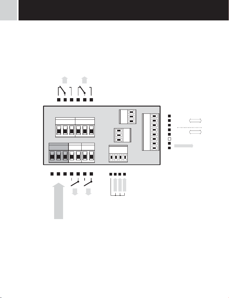
INSTRUMENT CONNECTION3
The instrument supply leads should not be in proximity of the incoming low-potential signals.
Contactors, motors with larger input power should not be in proximity of the instrument.
The leads into the instrument input (measured quantity) should be in sufficient distance from all power leads and appliances.
Provided this cannot be secured it is necessary to use shielded leads with connection to ground (bracket E).
The instruments are tested in compliance with standards for use in industrial area, yet we recommend to abide by the above
mentioned principles.
L3
8 9 10
1 2 3
-
+
L
N
POWER SUPPLY
E
L4
11 12 13
5 4
5 6 7
L1
L2
RxD/L+
TxD/L-
GND
GND
AO-I
AO-U
14 15 16 17
RxD
RS 232
+
-
TxD
GND
L+
L-
Excitation
RS 485
IV V VI
III II I
A B C D E F G H
EXT. 1
EXT. 3
EXT. 2
|
6
INSTRUCTIONS FOR USE OM 602RS

INSTRUCTIONS FOR USE OM 602RS
|
7

INSTRUMENT SETTING4
Setting PROFISetting LIGHT
• For expert users
• Complete instrument menu
• Access is password protected
• Possibility to arrange items of the
„User“ menu
• Tree menu structure
• For trained users
• Only items necessary for instrument
setting
• Access is password protected
• Possibility to arrange items of the
„User“ menu
• Linear menu structure
Setting USER
|
8
INSTRUCTIONS FOR USE OM 602RS
• For user operation
• Menu items are set by the user
(Profi/Light) as per request
• Access is not password protected
• Optional menu structure either tree
(PROFI) or linear (LIGHT)
4.1 Setting
The instrument is set and controlled by five control keys located on the front panel. All programmable settings of the instrument
are performed in three adjusting modes:
LIGHT Simple programming menu
- contains solely items necessary for instrument setting and is protected by optional number code
PROFI Complete programming menu
- contains complete instrument menu and is protected by optional number code
USER User programming menu
- may contain arbitrary items selected from the programming menu (LIGHT/PROFI), which determine
the right (see or change)
- acces without password
All programmable parameters are stored in the EEPROM memory (they hold even after the instrument is switched off).
Complete instrument operation and setting may be performed via OM Link communication interface, which is a standard
equipment of all instruments.
The operation program is freely accessible (www.orbit.merret.cz) and the only requirement is the purchase of OML cable
to connect the instrument to PC. It is manufactured in version RS 232 and USB and is compatible with all ORBIT MERRET
instruments.
Another option for connection is with the aid of data output RS 232 or RS 485 (without the need of the OML cable).
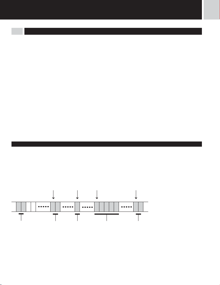
User data protocol
4INSTRUMENT SETTINGJE
Position
Position
Position
Position
12
Start
Address
Signum
Data
Stop
INSTRUCTIONS FOR USE OM 602RS
|
9

INSTRUMENT SETTING4
Setting and controlling the instrument is performed by means of 5 control keys located on the front panel. With the aid of
these keys it is possble to browse through the operation menu and to select and set required values.
Measured value
the last two places may display
measuring units
Ralay status
ON the digit is lit
OFF the digit is not lit
OFF the digit is flashing
limits withrestriction
(hysteresis, delay)
Symbols used in the instructions
DEF
values preset from manufacture
42
symbol indicates a flashing light (symbol)
MIN
inverted triangle indicates the item that can be placed in USER menu
MEMORY
broken line indicates a dynamic item, i.e. it is displayed only in particular selection/version
after pressing the key the set value will not be stored
after pressing the key the set value will be stored
30
continues on page 30
Setting the decimal point and the minus sign
DECIMAL POINT
Its selection in the menu, upon modification of the number to be adjusted it is performed by the control key with transition
beyond the highest decade, when the decimal point starts flashing . Positioning is performed by / .
4285.42
1T2M
M Min/max. value
T Tare
Function
THE MINUS SIGN
Setting the minus sign is performed by the key on higher decade. When editing the item substraction must be made from
the current number (e.g..: 013 >
|
10
INSTRUCTIONS FOR USE OM 602RS
, on class 100 > -87)

Control keys functions
Key Measurement Menu Setting numbers/selection
access into USER menu exit menu quit editing
programmable key function back to previous level move to higher decade
programmable key function move to previous item move down
programmable key function move to next item move up
programmable key function confi rm selection confi rm setting/selection
4INSTRUMENT SETTING
+
+
+
access into LIGHT/PROFI menu
direct access into PROFI menu
+
+
Setting items into „USER“ menu
• in LIGHT or PROFI menu
• no items permitted in USER menu from manufacture
• on items marked by inverted triangle
legend is flashing - current setting is displayed
+
---
NO
item will not be displayed in USER menu
YES
item will be displayed in USER menu with the option of setting
SHOW
item will be solely displayed in USER menu
NO YES SHOW
confi guration of an item for
“USER” menu
determine the sequence of items
in “USER - LIGHT” menu
return to item
INSTRUCTIONS FOR USE OM 602RS
numeric value is set to zero
---
|
11

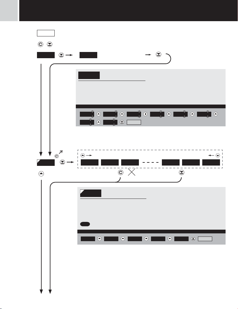
light
5
SETTING
5.0 Setting “LIGHT”
LIGHT Simple programming menu
- contains only items necessary for instrument setting and is protected by optional number code
Setting LIGHT
light
• For capable users
• Only items necessary for instrument
setting
• Access is password protected
• Possibility to arrange items of the
„User“ menu
• Linear menu structure
Preset from manufacture
Password “0”
Menu LIGHT
USER menu off
Setting the items
DEF
|
12
INSTRUCTIONS FOR USE OM 602RS
!
Upon delay exceeding 60 s the programming mode
is automatically discontinued and the instrument
itself restores the measuring mode
light
light
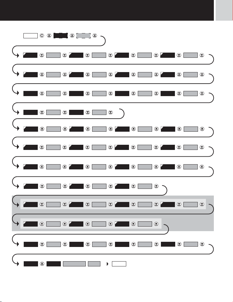
5SETTING
+
000.00MIN A
Access password
Instrument address
Setting - Integer Setting - Integer
Setting - Integer Setting - Integer
0MAX. 10MAX. 0
Setting - Float
100.00MAX. 9F000.00MIN. 9F
Setting - 2.innitial sequence Setting - Adrress position
Setting - Signum position Signum supression
Setting - Request (REQ.1…REQ.8) Setting - Communi. failure
Selection input range - max
100.00MAX A
Data protocol
MAX. 2
Projection
MAX. 2
ASCIIPROT.0ADD R.9600BAUD
DASHESMOD T.O.REQ. 1REQUES.STO P 1STO P
0000. ooFOR M. A
Commaand
Setting - Integer
0MIN . 20MIN . 10MIN . 0
Setting - Integer
0
Setting - 1.address symbol
0AD . POS.0START. 22STA RT.1
Setting - Data position
YESPL. SUP.0SI . POS.49ADR . 2
Setting - Timeout
142.8 PASSW. 0
Baud rate
Setting - Integer
Setting - Integer
Setting - Float
Setting - 1.innitial sequence
Setting - 2.address symbol
Setting - closing sequence
Selection input range - min
LIM . L.1 20 LIM . L.2 40 LIM . L.3 60 LIM . L.4 80
0COMMA.
0MAX. 3
100MAX. 3
48Adr. 1
0DA. POS.
1. 0TIMEOU.
Option - comparator
TYP . A .O. MIN A .O. MAX A. O. 1000I 20
Menu type
MENU LIG HT RE. SET. FIRM LANG. ENGL .
Identifi cation
Return to manufacture setting
Instrument type
OM602RS
SW number
64
Language selection
Return to measur-
142.8IDENT . YES
ing mode
INSTRUCTIONS FOR USE OM 602RS
Option - Analog output
New password
PAS. LI. 0
|
13
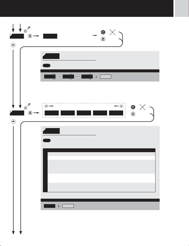
5
light
SETTING
142.8
light
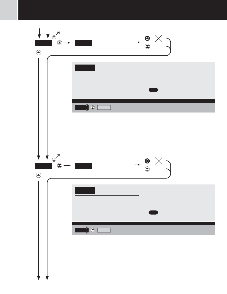
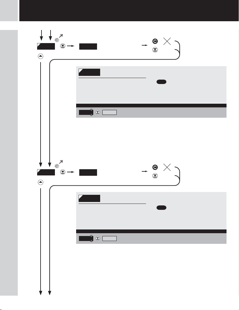
PASSW . 0
PASSW .
PAS = 0
- access into menu is unrestricted, after
releasing keys you automaticaly move to first
item of the menu
Set “Pas sword” = 42 Example
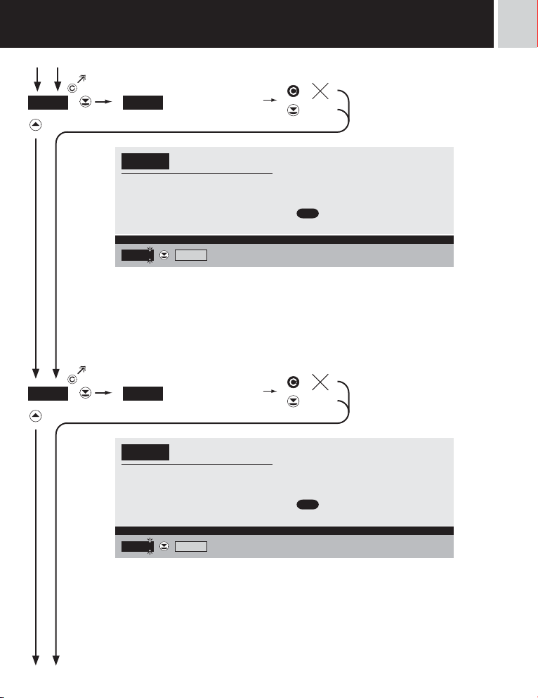
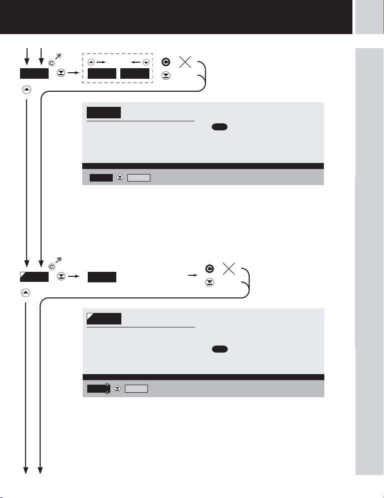
32 BAUD
BAUD
600 1200 2400 576 00 11 5 2 0 0 230400
BAUD
- selection of range: 600/1200/2400/960
0/19200/38400/57600/115200/2304
00 Baud
= 9600
DEF
Selec tion of rate 115200 B aud > BAUD = 115200 Example
9600 3840019200
Entering access password
for access into the menu
Access into instrument
menu
PAS > 0
- access into menu is protected ny number
code
0 1 2 02 12
42
Selection of transmission
rate of the data output
57600
11 5 2 0 0
22
ADDR.
|
14
INSTRUCTIONS FOR USE OM 602RS
light
light
SETTING
5
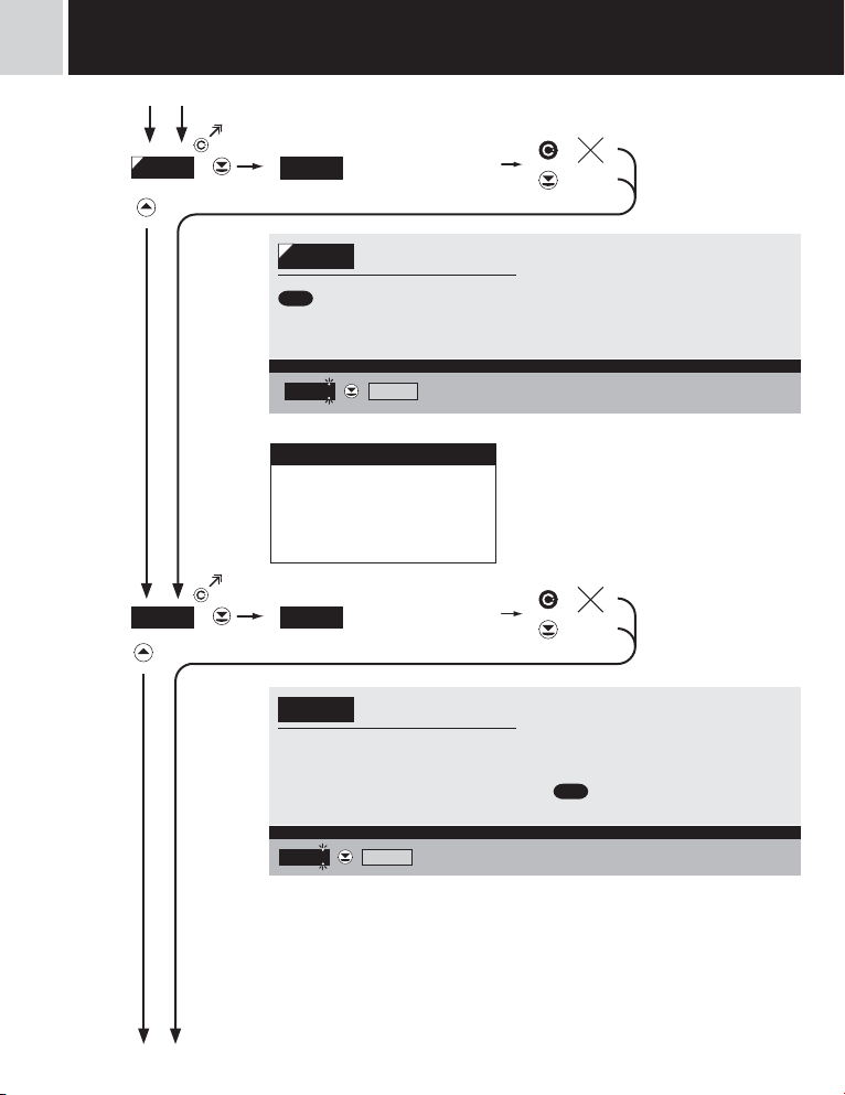
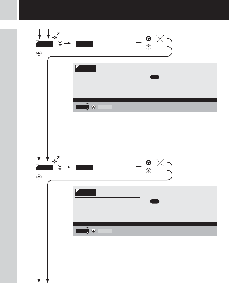
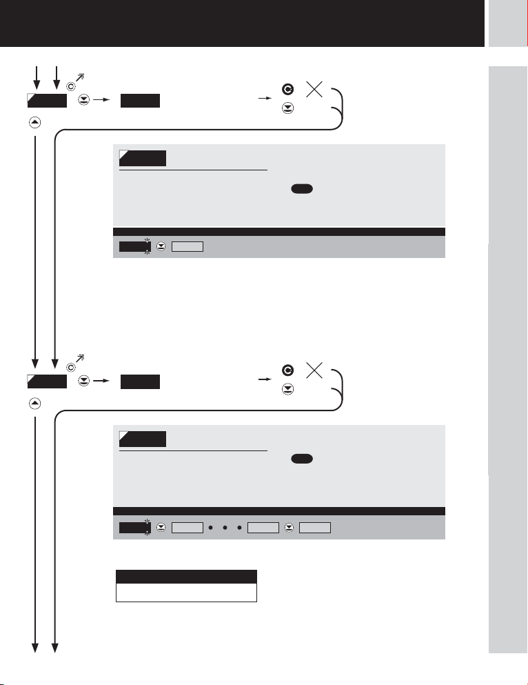
ADDR .
PROT.
Setting instrument
0
address
Setting instrument address
ADDR .
= 0
DEF
Addres s 10 > ADDR. = 10 Example
0 10 00 PROT.
ASCII M. BUS MASTER SLAVE
Selection of data protocol
PROT.
= ASCII
DEF
Menu Description
ASCII Data protocol ASCII
M. BUS Data protocol DIM MessBus
MASTER
PROT.
SLAVE
UNIVER.
Instrument solicits data from subordinate system
- instrument controls data tansmission from subordinate system
- “COMMAN” may be used for selection of received data (for commands see data protocol)
- instrument asks 10 questions/s, if no response arrives within 2 sthe display shows “ - - - Passive display - slave is used where there is communication of other isntruments or a computer
in the “MASTER” mode. If “COMMAND” is correctly received, the instrumetns will display
the data.
Universal protocol
- in dynamic v dynamických items (Start, Adr-Un, Num Sign, Data, Stop, Request) cutom
protocol can be set up.
UNIVER.
Data pr otocol = ASCI I > ASCII Example
* subsequent item on the menu depends on instrument setting
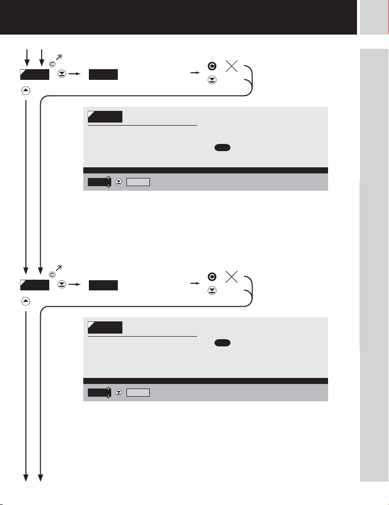
COMMA.ASCII
INSTRUCTIONS FOR USE OM 602RS
|
15
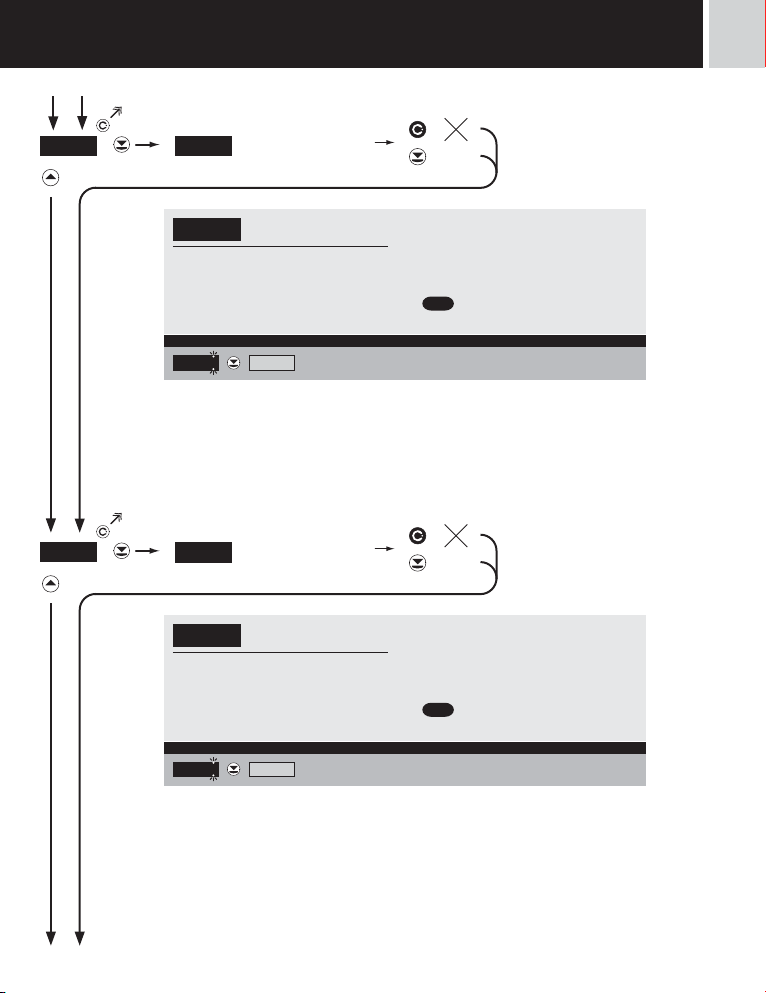
5
light
SETTING
light
COMMA.
MIN . 0
Setting - Command
0
Setting - Command
COMMA.
= uu (two spaces)
DEF
Comman d > uu Example
uu
MIN. 0
* subsequent item on the menu depends on instrument setting
!
If is „COMMAND“ „uu“ (two spaces) is broadcast
query on data #AA<CR>.
Else #AA<<COMMAND>><CR> will wait on
confirmation „!AA“ and after it will send out request
about data #AA<CR>
Selection of integer intput
0
range - min 0
Selection integer input
MIN . 0
range - min - MSB
- setting minimum value of input data, it is
entered by individual bytes in range 0…255
- the input data format is sign integer 32 bits
- range: -2147483648…2147483647
(0x80000000…0x7FFFFFFF)
= 0
DEF
|
16
INSTRUCTIONS FOR USE OM 602RS
Selec tion integ er input ran ge > MIN.0 = 0 Example
0 MIN. 1
light
light
SETTING
5
MIN . 1
MIN . 2
Selection of integer intput
0
range - min 1
Selection of integer input
MIN . 1
range - min
- setting minimum value of input data, it is
entered by individual bytes in range 0…255
- the input data format is sign integer 32 bits
Selec tion integ er input ran ge > MIN.1 = 0 Example
0 MIN. 2
Selection of integer intput
0
range - min 2
Selection of float input
MIN . 2
range - min
- setting minimum value of input data, it is
entered by individual bytes in range 0…255
- the input data format is sign integer 32 bits
- range: -2147483648…2147483647
(0x80000000…0x7FFFFFFF)
= 0
DEF
- range: -2147483648…2147483647
(0x80000000…0x7FFFFFFF)
= 0
DEF
Selec tion integ er input ran ge > MIN.2 = 0 Example
0 MIN. 3
INSTRUCTIONS FOR USE OM 602RS
|
17
5
light
SETTING
light
MIN . 3
MAX. 0
Selection of integer intput
0
range - min 3
Selection of integer input
MIN . 3
range - min - LSB
- setting minimum value of input data, it is
entered by individual bytes in range 0…255
- the input data format is sign integer 32 bits
Selec tion integ er input ran ge > MIN.3 = 0 Example
0 MAX. 0
Selection of integer intput
0
range - max 0
Selection of integer input
MAX. 0
range - max - MSB
- setting maximum value of input data, it is
entered by individual bytes in range 0…255
- the input data format is sign integer 32 bits
- range: -2147483648…2147483647
(0x80000000…0x7FFFFFFF)
= 0
DEF
- range: -2147483648…2147483647
(0x80000000…0x7FFFFFFF)
= 0
DEF
|
18
INSTRUCTIONS FOR USE OM 602RS
Selec tion integ er input ran ge > MAX. 0 = 0 Example
0 MAX. 1
light
light
SETTING
5
MAX. 1
MAX. 2
Selection of integer intput
0
range - max 1
Selection of integer input
MAX. 1
range - max
- setting maximum value of input data, it is
entered by individual bytes in range 0…255
- the input data format is sign integer 32 bits
Selec tion integ er input ran ge > MAX.1 = 0 Example
0 MAX. 2
Selection of integer intput
0
range - max 2
Selection of integer input
MAX. 2
range - max
- setting maximum value of input data, it is
entered by individual bytes in range 0…255
- the input data format is sign integer 32 bits
- range: -2147483648…2147483647
(0x80000000…0x7FFFFFFF)
= 0
DEF
- range: -2147483648…2147483647
(0x80000000…0x7FFFFFFF)
= 0
DEF
Selec tion integ er input ran ge > MAX.1 = 0 Example
0 MAX. 3
INSTRUCTIONS FOR USE OM 602RS
|
19

5
light
SETTING
light
MIN . 3
MAX. 0
Selection of integer intput
0
range - min 3
Selection of integer input
MIN . 3
range - min - LSB
- setting minimum value of input data, it is
entered by individual bytes in range 0…255
- the input data format is sign integer 32 bits
Selec tion integ er input ran ge > MIN.3 = 0 Example
0 MAX. 0
Selection of integer intput
0
range - max 0
Selection of integer input
MAX. 0
range - max - MSB
- setting maximum value of input data, it is
entered by individual bytes in range 0…255
- the input data format is sign integer 32 bits
- range: -2147483648…2147483647
(0x80000000…0x7FFFFFFF)
= 0
DEF
- range: -2147483648…2147483647
(0x80000000…0x7FFFFFFF)
= 0
DEF
|
20
INSTRUCTIONS FOR USE OM 602RS
Selec tion integ er input ran ge > MAX. 0 = 0 Example
0 MAX. 1

light
light
SETTING
5
MAX. 1
MAX. 2
Selection of integer intput
0
range - max 1
Selection of integer input
MAX. 1
range - max
- setting maximum value of input data, it is
entered by individual bytes in range 0…255
- the input data format is sign integer 32 bits
Selec tion integ er input ran ge > MAX.1 = 0 Example
0 MAX. 2
Selection of integer intput
0
range - max 2
Selection of integer input
MAX. 2
range - max
- setting maximum value of input data, it is
entered by individual bytes in range 0…255
- the input data format is sign integer 32 bits
- range: -2147483648…2147483647
(0x80000000…0x7FFFFFFF)
= 0
DEF
- range: -2147483648…2147483647
(0x80000000…0x7FFFFFFF)
= 0
DEF
Selec tion integ er input ran ge > MAX.1 = 0 Example
0 MAX. 3
INSTRUCTIONS FOR USE OM 602RS
|
21
5
light
SETTING
light
Setting Universal protocol
STA RT.1
STA RT.2
DEF
DEF
= 2
= 0
Setting - 1. Start symbol
2
STA RT.1
- set directly in ASCII code
- range: 1…127
Setti ng 1.Start s ymbol > STAR T. 1 = 2 Example
STA RT.2
- set directly in ASCII code
- range: 1…127
- if set to “0”, it will not be used
Setting the first intrductory
symbol
2 STAR T.2
Setting - 2. Start symbol
0
Setting the second
intrductory symbol
|
22
INSTRUCTIONS FOR USE OM 602RS
Setti ng 2.Star t symbol > ST ART. 2 = 0 Example
0 AD. POS.
light
light
SETTING
5
AD . POS.
ADR . 1
Setting the address
0
position
0 ADR. 1
48
Adr. 1
Setting the address
position
Setting - 1. address
symbol
First address symbol
AD . POS.
- Position of the address and other symbols
which have to have a set value. If set to 0,
the block will not be taken into account. The
block can be anywhere in the message.
Setti ng address p osition > Ad . POS. = 0 Example
- set directly in ASCII code
- range: 0…127
- range: 0…245
= 0
DEF
= 48
DEF
Setting Universal protocol
Setti ng 1.addres s symbol > Ad r. 1 = 48 Example
48 AD R. 2
INSTRUCTIONS FOR USE OM 602RS
|
23
5
light
SETTING
light
Setting Universal protocol
ADR . 2
SI. POS.
DEF
DEF
= 49
= 0
Setting - 2. address
49
symbol
Second address symbol
Adr. 2
- set directly in ASCII code
- range: 0…127
- if set to “0”, it will not be used
Setti ng 2. addre ss symbol > Ad r. 2 = 49 Example
49 SI . POS.
Setting - Signum position
0
Setting number sign
SI. POS.
position
- Number sign position. If set to 0, it has to
be part of the data. This symbol can appear
anywhere within the message.
- range: 0…245
Setti ng positio n > SI. POS. = 0 Example
0 PL. SUP.
|
24
INSTRUCTIONS FOR USE OM 602RS
light
light
SETTING
5
PL. SUP.
DA. POS.
YES NO
„Plus“ number sign
PL. SUP.
supression
- option “YES” > number sign “plus” will be
replaced by space
- option “NO” > number sign “plus” will be
displayed
Sign sup ression > PL . SUP. = YES Example
ANO
DA. POS.
- Data position. This block can be anywhere
within the message. If ending sequence
is received sooner than the set number
of symbols, it is considered a succcesful
reception.
Setti ng data posi tion > dA. P OS. = 0 Example
DA. POS.
Setting data position
1
Setting data position
1 DA. LEN .
= YES
DEF
- range: 1…245
= 1
DEF
Setting Universal protocol
INSTRUCTIONS FOR USE OM 602RS
|
25

5
light
SETTING
light
Setting Universal protocol
DA. LEN .
STO P 1
Setting number of signs
6
Setting number of signs
DA. LEN .
- 7 symbols can be displayed only if there is
no !minus” sign and one of the symbols is
decimal point-
Setti ng number of s igns > DA. LE N. = 6 Example
6 ST OP 1
Setting - 1. Stop symbol
3
Setting the first closing
STO P 1
symbol
- set directly in ASCII code
- range: 0…127
- If set to 0, the closing block will not be taken
into account.
Setti ng 1. Stop sym bol > STOP 1 = 3 Example
3 ST OP 2
- range: 1…7
= 6
DEF
= 3
DEF
|
26
INSTRUCTIONS FOR USE OM 602RS
light
light
SETTING
5
STO P 2
REQ. 1
DEF
DEF
= 0
= 0
Setting - 2. Stop symbol
0
Setting the second closing
STO P 2
symbol
- set directly in ASCII code
- range: 0…127
- If set to 0, the block will not be taken into
account.
Setti ng 2. Stop sy mbol > STOP 2 = 3 Example
2 REQ. 1
Setting fi rst symbol of the
0
request
First symbol of the request
REQ. 1
- set directly in ASCII code
- range: 0…127
- If set to “0”, request is not sent
Setting Universal protocol
Setti ng - 1. symbol > R EQ. 1 = 0 Example
0
REQ. 2
REQ. 8 MOD T.O .
*
Same procedure for REQ. 2…REQ. 8
INSTRUCTIONS FOR USE OM 602RS
|
27

5
light
SETTING
light
MOD T.O .
TIMEOU.
NO BLANK FLA SH DASHES
MOD T.O .
failure
MOD T.O.
Selec ton mode > Das hes Example
Selecting display mode
in case of communication
Menu Description
NO No reaction
BLANK Display goes of f
FLASH Last displayed value starts flashing
DASHES Dash symbols displayed
DOT Decimal point is displayed
TIMEOU.DASHES
!
Item will not appear in “MASTER” protocol
Setting - Timeout constant
6
TIMEOU.
- setting the time delay after which the
indication of interrupted communication will
appear on the display in the mode of
“Mod t.0.”
Setti ng - Consta nt > tIMEOU . = 1 Example
Setting the time constant
for Timeout
1.0 FO RM . A
DOT
= DASHES
DEF
- range: 0…99,9 s
-
= 1.0 s
DEF
30
|
28
INSTRUCTIONS FOR USE OM 602RS
!
Item will not appear in “MASTER” protocol and when
“MOD t.0.” is disabled

light
light
SETTING
5
MIN A
MAX A
000. 00
- range of the setting is -99999…999999
- position of the DP does not affect display
projection
Projec tion for min > M IN A = 0.00 Example
000.00 MAX A
100. 00
- range of the setting is -99999…999999
- position of the DP does not affect display
projection
Projec tion for ma x > MAX A = 100.0 0 Example
100. 00 FO RM . A
Selection of integer intput
range - max
Selection of integer input
MIN A
range - max
Selection of fl oat intput
range - min
Selection of float input
MAX A
range - min
- the DP is automatically shifted after the
value is confirmed
= 0.00
DEF
- the DP is automatically shifted after the
value is confirmed
= 100.00
DEF
Setting ASCII protocol with active setting 9n and 9F
INSTRUCTIONS FOR USE OM 602RS
|
29

5
light
SETTING
light
FOR M. A
000000 00000. o 0000. oo 000.ooo 00. oooo 0. ooooo FLO A. P.
Setting projection of the
FOR M. A
decimal point
= 0000.oo
- positioning of the DP is set here in the
measuring mode
Projection of DP on display > 00000.o Example
0000. oo 00000. o
COL. 0
DEF
*subsequent item on the menu depends on instrument equipment
|
30
INSTRUCTIONS FOR USE OM 602RS

light
light
SETTING
5
INSTRUCTIONS FOR USE OM 602RS
|
31

5
light
SETTING
light
LIM . L.1
Displayed only with options > Comparators
LIM . L.2
- range of the setting is -99999…999999
- default “Hysteresis”=0 “Delay”=0
Setti ng limit 1 > LI M L 1 = 32 Example
LIM . L.2
- range of the setting is -99999…999999
- default “Hysteresis”=0 “Delay”=0
Setti ng limit 2 > LI M L 2 = 53.1 Example
000531 000531. 00053 .1
Setting boundary for
20
limit 1
Setting boundary for
LIM . L.1
limit 1
20 22 21 32 22
Setting boundary for
40
limit 2
Setting boundary for
limit 2
40 41 41 131 031 31
231
331
- contingent modification of hysteresis or
delay may be performed in “PROFI” menu
= 20
DEF
MENU
- contingent modification of hysteresis or
delay may be performed in “PROFI” menu
= 40
DEF
* subsequent item on the menu depends on instrument
MENU
equipment
00531 0531 531 431
|
32
INSTRUCTIONS FOR USE OM 602RS
!
Items for “Limits” and “Analog output” are accessible only if incorporated in the instrument.

light
light
SETTING
5
LIM . L.3
LIM . L.4
Setting boundary for
60
limit 3
Setting boundary for
LIM . L.3
limit 3
- range of the setting is -99999…999999
- default “Hysteresis”=0 “Delay”=0
Setti ng limit 3 > LI M L 3 = 85 Example
60 62 61 64 63
7565 85 MENU
Setting boundary for
80
limit 4
Setting boundary for
LIM . L.4
limit 4
- range of the setting is -99999…999999
- default “Hysteresis”=0 “Delay”=0
Setti ng limit 4 > LI M L 4 = 103 Example
80 82 81 938383
03
003 MENU
103
- contingent modification of hysteresis or
delay may be performed in “PROFI” menu
= 60
DEF
65
* subsequent item on the menu depends on instrument
equipment
- contingent modification of hysteresis or
delay may be performed in “PROFI” menu
= 80
DEF
* subsequent item on the menu depends on instrument
equipment
Displayed only with options > Comparators
INSTRUCTIONS FOR USE OM 602RS
|
33

5
light
SETTING
light
TYP . A . O.
Displayed only with options > Analog output
MIN A .O.
0-20 mA E. 4-20 4-20 mA 0-5m A 0-2 V 0-5 V 0-1 0 V
0-10 V
MIN A .O.
Setting the type of analog
TYP . A . O.
output
Menu Range Description
0-20mA 0…20 mA
E. 4-20mA 4…20 mA with indication of error statement (<3,6 mA)
4-20mA 4…20 mA
0-5mA 0…5 mA
0-2 V 0…2 V
0-5 V 0…5 V
0-10 V 0…10 V
= 4…20 mA
DEF
Type of an alog outpu t - 0...10 V > TYP. A.O. = 0 -10 V Example
4-20m A 0-2 V0-5mA
Assigning the display
0
value to the beginning of
the AO range
MIN A .O.
the AO range
- range of the setting is -99999…999999
Displ ay value for th e beginni ng of the AO rang e > MIN A.O. = 0 Example
Assigning the display
value to the beginning of
0
MAX A.O.
0-5 V
DEF
= 0
|
34
INSTRUCTIONS FOR USE OM 602RS
!
Items for “Limits” and “Analog output” are accessible only if incorporated in the instrument.

light
light
SETTING
5
MAX A.O.
DEF
= 100
Assigning the display
100
value to the end of the
AO range
MAX A.O.
AO range
- range of the setting is -99999…999999
Displ ay value for th e end of the AO ra nge > MAX A .O. = 120 Example
Assigning the display
value to the end of the
100 100 120 110 MENU
Displayed only with options > Analog output
INSTRUCTIONS FOR USE OM 602RS
|
35

5
light
SETTING
light
MENU
RE. SET.
LIGHT PROFI
Setting the menu type
MENU
LIGHT/PROFI
LIGHT > menu LIGHT, a simple menu,
which contains only the most essential items
necessary for instrument setting
> linear tree structure
Menu LIG HT > MENU = LI GHT Example
LIGHT
RE. SET.
PROFI > menu PROFI, a complete menu for
complete instrument setting
> tree menu structure
= LIGHT
DEF
TYP E USER
Restoration of manufacture
RE. SET.
instrument setting
- in the event of error setting the manufacture
setting may be restored
- restoration is performed for the currently
selected type of the instrument input (select
“TYPE”)
Restora tion of man ufacture s etting > RE . SET. Example
RE. SET.
TYP E
LANG.
- provided you stored your user setting in
the “PROFI” menu, it may also be restored
(select “USER”)
- loading manufacture calibration and
primary setting of items on the menu (DEF)
|
36
INSTRUCTIONS FOR USE OM 602RS

light
light
SETTING
5
LANG.
PAS. LI.
CZECH EN GL.
Selection of language in
LANG.
instrument menu
- selection of language version of the
instrument menu
Langua ge selecti on - ENGLIS H > LANG. = EN GL. Example
PAS. LI. EN GL.
Setting new access
0
password
Setting new access
PAS. LI.
password
- access password for menu LIGHT
- range of the number code 0…9999
New pass word - 341 > PAS. LI . = 341 Example
0
41 041 341 241 141
1 01 11 21 31
= ENGL.
DEF
- upon setting the password to “000” the
access to menu LIGHT is free without
prompt to enter it
- in the event of loss universal password
“8177” may be used
= 0
DEF
IDENT.
INSTRUCTIONS FOR USE OM 602RS
|
37

5
light
SETTING
IDEN T.
light
YES
setting the input typeSW number SW versioninstrument type
OM 602RS 64- 139 SLAVE
142.8
IDEN T.
- the display shows the type of instrument
indication, SW number, SW version and
current input setting (Mode)
Return to measuring mode
Instrument SW version
- if SW version contains a letter in first
position, then it is a customer SW
- after the identification is completed the
menu is automatically exited and the
instrument restores the measuring mode
|
38
INSTRUCTIONS FOR USE OM 602RS

light
light
SETTING
5
INSTRUCTIONS FOR USE OM 602RS
|
39

6
profi
SETTING
6.0 Setting “PROFI”
PROFI Complete programming menu
• contains complete instrument menu and is protected by optional number code
• designed for expert users
• preset from manufacture is menu LIGHT
SETTING PROFI
Switching over to “PROFI” menu
profi
• For expert users
• Complete instrument menu
• Access is password protected
• Possibility to arrange items of the
„User“ menu
• Tree menu structure
• temporary switch-over to PROFI menu, which is suitable to edit a few items
+
• after quitting PROFI menu the instrument automatically switches to LIGHT menu
• access is password protected (if it was not set under item N. PASS. =0)
+ • access into LIGHT menu and transition to item „MENU“ with subsequent selection of „PROFI“ and
confirmation
• after re-entering the menu the PROFI type is active
• access is password protected (if it was not set under item N. PASS. =0)
|
40
INSTRUCTIONS FOR USE OM 602RS

profi
profi
SETTING
6
INSTRUCTIONS FOR USE OM 602RS
|
41

6
profi
SETTING
6.1 Setting “PROFI” - INPUT
profi
INPUTS
CHANNE.
OUTPUT. EXT. IN .
SERVIC.
6.1.1 Resetting internal values
INPUTS CL. TAR.
CHANNE.
OUTPUT.
SERVIC.
CLEAR
CONFIG.
KEYS
CLEAR
CONFIG.
EXT. IN .
KEYS
CL. M.M.
The primary instrument parameters are
set in this menu
Resetting internal
CLEAR
values
EXT. IN .
KEYS
CLEAR
CL. TA R.
CL. M .M .
Selection of measuring
range and parameters
Setting external inputs
functions
Assigning further
functions to keys on the
Resetting internal values
Tare resetting
Resetting min/max value
CONFIG.
instrument
- resetting memory for the storage of
minimum and maximum value achieved
during measurement
|
42
INSTRUCTIONS FOR USE OM 602RS

profi
profi
6.1.2a Selection of data baud rate
KEYS
BAUD
ADDR .
ADR . P.B.
PROT.
COMMA.
MIN . 9N
MAX. 9N
MIN . 9F
MAX. 9F
Start
ADR .-Un.
SIGNUM
DATA
STO P
REQUES .
MOD T.O .
TIMEOU.
600
1200
2400
4800
9600
19200
38400
576 00
11 5 2 0 0
230400
DEF
19200
38400
576 00
11 5 2 0 0
230400
INPUTS
CHANNE.
OUTPUT.
SERVIC.
CLEAR
CONFIG.
EXT. IN .
SETTING
Selection of data baud
BAUD
rate
Rate - 600 Baud
600
Rate - 1200 Baud
1200
Rate - 2400 Baud
2400
Rate - 4800 Baud
4800
Rate - 9600 Baud
9600
Rate - 19200 Baud
Rate - 38400 Baud
Rate - 57600 Baud
Rate - 115200 Baud
Rate - 230 400 Baud
6
6.1.2b Setting instrument address
INPUTS
OUTPUT.
SERVIC.
CLEAR
CONFIG.
EXT. IN .
KEYS
BAUD
ADDR .CHANNE.
ADR . P.B.
PROT.
REQUES .
MOD T.O .
TIMEOU.
00
DEF
INSTRUCTIONS FOR USE OM 602RS
Setting instrument
ADDR .
address
- setting in range 0…31
-
= 00
DEF
ADR . P.B.
- setting in range 0…125
-
DEF
Setting instrument
address - PROFIBUS
= 19
!
When selecting the “UNIVER.” protocol, the address
is set in “Adr-Un.”
|
43

6
profi
e
SETTING
profi
+
142.8
INPUT S CHANNE.
CLEAR
CONFIG.
HESLO 0
CL. TAR. CL. M.M.
BAUD
ADDR .
00
ADR . P.B. 19
PROT
COMMA. --
MIN. 9N
MAX. 9N
MIN. 9F
MAX. 9F 100.00
STAR T
SIGNUM
ADDR .
DATA
000.00
600 1200 230400
ASCII M. BUS UNIVER.
MIN. 0 MIN. 1 MIN. 3
MAX. 0 MAX. 1 MAX. 3
START.1 START.2
AD. POS. ADR. 1 ADR. 2
SI. POS. PL. SUP..
DA. POS. DA. LEN.
Access password
MAT. FN .
SET. ACHAN. A
FILTER
FOR M. A
DESC. A
MATH. F.
CON . A 0
CON . F 0
FOR M. M
DESC. M 00
Programming sch
MIN A
0
MAX A 100
P. TAR . A 0
MOD F. A
CON . F.A 0
000000 00000.o FLOA.. P.
00
NO MULTIN. 1/MUL. SIN X
000000 00000.o FLOA. P.
NO AVER. ROUND
STOP
REQUES.
EXT. IN .
KEYS LEFT
44
EXT. 1
M. HOLD
ENTER
|
INSTRUCTIONS FOR USE OM 602RS
STOP 1 STOP 2
REQ. 1 DOT.. 2 REQ. 8
NO HOLD SAVE
DISPL. D. +A.O.. D.+A.O..+L. ALL
FN. LE .
TMP. LE .
MNU. LE.
NO
NO
LIM. 1
MIN. MAX. INP . M.M.
NO CHAN. A FIL. A MATF.

profi
me PROFI MENU
profi
SETTING
6
OUTPUT.
LIMITS LIM . 1
LIM . 4
AN. OUT. INP . A.O .
TYP . A .O.
DISP. PERM.
BRIGHT
INP. L .1
MOD L.1
TYP . L.1
LIM . L.1 20
HYS. L1 . 0
ON L.1
OFF L.1
PER. L.1 0
TIM . L.1
NO CHAN. A FIL. A MAT. FN. MIN MAX
0-20mA Er.4-20 4-20mA 0-5mA 0-2 V 0-5 V 0-10
0MIN A .O.
100MAX A.O.
CHAN. A FIL. A MAT. FN. MIN MAX
0% 25% 50% 75% 100%
NO CHAN. A FIL. A MAX
HYSTER. FROM. . DOSING
CLOSE OPEN
0
0
0
SERVIC.
MENU
RESTOR.
LANG.
IDENT . OMD 201RS. .. .
LIGHT PROFI
RE. SET. FIRM
SAVE
CZECH ENGL..
PAS. LI.
PAS. Pr.
USER
0N. PASS.
!
Upon delay exceeding 60 s the programming mode
is automatically discontinued and the instrument
itself restores the measuring mode
INSTRUCTIONS FOR USE OM 602RS
|
45

6
profi
SETTING
6.1.2c Selection of data protocol
INPUTS
CHANNE.
OUTPUT.
SERVIC.
CLEAR
CONFIG.
EXT. IN .
KEYS
BAUD
ADDR .
ADR . P.B.
PROT.
COMMA.
MIN . 9N
MAX. 9N
MIN . 9F
MAX. 9F
STA RT
ADR .-Un.
SIGNUM
DATA
STO P
REQUES .
MOD T.O .
TIMEOU.
profi
ASCII
M.BUS
MASTER
SLAVE
UNIVER.
DEF
Selection of data
PROT.
protocol
Data protocol
ASCII
ASCII
Data protocol
M. BUS
DIN MessBus
SLAVE
Instrument solicits data
from subordinate system
Passive Display - Slave
Universal protocol
MASTER
- instrument controls data tansmission from
subordinate system
- “COMMAN” may be used for selection
of received data (for commands see data
protocol)
- instrument asks 10 questions/s, if no
response arrives within 2 sthe display
shows “ - - - -
- passive display - slave is used where there
is communication of other isntruments or
a computer in the “MASTER” mode. If
“COMMAND” is correctly received, the
instrumetns will display the data.
UNIVER.
- in dynamic v dynamických items (Start,
Adr-Un, Num Sign, Data, Stop, Request)
cutom protocol can be set up.
!
If is „COMMAND“ „uu“ (two spaces) is broadcast
query on data #AA<CR>.
Else #AA<<COMMAND>><CR> will wait on
confirmation „!AA“ and after it will send out request
about data #AA<CR>
|
46
INSTRUCTIONS FOR USE OM 602RS

profi
profi
6.1.2d Selection of integer input range - minimum ASCII, MESSBUS
INPUTS
CHANNE.
OUTPUT.
SERVIC.
6.1.2e Selection of integer input range - maximum ASCII, MESSBUS
CLEAR
CONFIG.
EXT. IN .
KEYS
ADDR .
PROT.
COMMA.
MIN. 9N
MAX. 9N
MIN . 9F
MAX. 9F
MOD T.O .
TIMEOU.
MIN . 0
MIN . 1
MIN . 2
MIN . 3
0BAUD
MIN . 9N
- setting minimum value of input data, it
is entered by individual bytes in range
0…255
- the input data format is sign integer 32
bits
- range: -2147483648…2147483647
(0x80000000…0x7FFFFFFF)
-
DEF
- - - -
SETTING
Selection of integer input
range - min
= 0
Most significant byte -
MIN . 0
“MSB”
Least significant byte
MIN . 3
- “LSB”
6
INPUTS
CHANNE.
OUTPUT.
SERVIC.
CLEAR
CONFIG.
EXT. IN .
KEYS
BAUD
ADDR .
PROT.
COMMA.
MIN . 9N
MAX. 9N
MIN . 9F
MAX. 9F
MOD T.O .
TIMEOU.
MAX. 0
MAX. 1
MAX. 2
MAX. 3
MAX. 9N
0
- setting minimum value of input data, it
is entered by individual bytes in range
0…255
- the input data format is sign integer 32
bits
- range: -2147483648…2147483647
(0x80000000…0x7FFFFFFF)
-
DEF
- - - -
-
DEF
INSTRUCTIONS FOR USE OM 602RS
Selection of integer input
range - max
Most significant byte -
MAX. 0
“MSB”
= 100
Least significant byte
MAX. 3
- “LSB”
= 100
|
47

6
profi
SETTING
6.1.2f Selection of float input range - minimum
INPUTS
CHANNE.
OUTPUT.
SERVIC.
6.1.2g Selection of float input range - maximum
CLEAR
CONFIG.
EXT. IN .
KEYS
BAUD
ADDR .
PROT.
COMMA.
MIN . 9N
MAX. 9N
MIN. 9F
MAX. 9F
MOD T.O .
TIMEOU.
profi
000. 00
Selection of float input
MIN . 9F
range - min.
- setting minimum value of input data
- input data format is float according to
standard IEEE -754, 32 bits
- range: 0.3×10
-
DEF
-38
= 0
<= |x| <= 1.7×1038
CLEAR
CONFIG.
EXT. IN .
KEYS
COMMA.
MIN . 9N
MAX. 9N
MIN . 9F
MAX. 9F
MOD T.O .
TIMEOU.
INSTRUCTIONS FOR USE OM 602RS
48
INPUTS
CHANNE.
OUTPUT.
SERVIC.
|
BAUD
ADDR .
PROT.
100. 00
Selection of float input
MAX. 9F
range - max
- setting minimum value of input data
- input data format is float according to
standard IEEE -754, 32 bitsrange: 0.3×10
-
DEF
= 100
-38
<= |x| <= 1.7×1038

profi
profi
6.1.2h Selecting display mode in case of communication failure
SETTING
6
INPUTS
CHANNE.
OUTPUT.
SERVIC.
6.1.2i Setting the time constant for Timeout
CLEAR
CONFIG.
EXT. IN .
KEYS
BAUD
ADDR .
PROT.
COMMA.
MIN . 9N
MAX. 9N
MIN . 9F
MAX. 9F
MOD T.0.
TIMEOU.
NO
BLANK
FLASH
DASHES
DOT
INPUTS
CHANNE.
OUTPUT.
SERVIC.
CLEAR
CONFIG.
EXT. IN .
KEYS
BAUD
ADDR .
PROT.
COMMA.
MIN . 9N
MAX. 9N
MIN . 9F
MAX. 9F
MOD T.O .
TIMEOU.
1. 0
DEF
DEF
BLANK
FLASH
DOT
NO
Selecting display
mode in case of
No reaction
Displey goes off
Last displayed value
starts flashing
Dash symbols displayed
Decimal point is
displayed
MOD T.0 .
communication failure
DASHES
!
Item will not appear in “MASTER” protocol
TIMEOU.
- setting the time delay after which the
indication of interrupted communication
will appear on the display in the mode of
“Mod t.0.”
- range: 0…99,9 s
-
DEF
Setting the time constant
for Timeout
= 1.0 s
!
Item will not appear in “MASTER” protocol and when
“MOD t.0.” is disabled
INSTRUCTIONS FOR USE OM 602RS
|
49

6
profi
SETTING
6.1.2j Setting innitial two-symbol sequence Protocol “UNIVERSAL”
profi
INPUTS BAUD
CHANNE.
OUTPUT.
SERVIC.
6.1.2k Seting the instrument address Protocol “UNIVERSAL”
CLEAR
CONFIG.
EXT. IN .
KEYS
PROT.
START
ADDR .
SIGNUM
DATA
STO P
REQUES .
MOD T.O .
TIMEOU.
STA RT.1
STA RT.2
2
- set directly in ASCII code
- range: 1…127
-
DEF
STA RT.2
- set directly in ASCII code
- range: 0…127
- if set to “0”, it will not be used
-
DEF
PROT.
STA RT
ADDR.
DATA
STO P
AD . POS.
ADR . 1
ADR . 2
0
- either address in universal protocol or one
(or two) symbols of fixed value
- Position of the address and other symbols
which have to have a set value. If set to 0,
the block will not be taken into account.
The block can be anywhere in the
message.
- range: 0…245
-
DEF
- set directly in ASCII code
- range: 0…127
-
DEF
- set directly in ASCII code
- range: 0…127
- if set to “0”, it will not be used
-
DEF
INPUTS BAUD
CHANNE.
OUTPUT.
SERVIC.
CLEAR
CONFIG.
EXT. IN .
KEYS
SIGNUM
REQUES .
MOD T.O .
TIMEOU.
STA RT
STA RT.1
ADDR .
AD . POS.
ADR . 1
ADR . 2
= 2
= 0
= 0
= 48
= 49
Setting innitial twosymbol sequence
Setting the first
intrductory symbol
Setting the second
introductory symbol
Setting the instrument
address
Setting the address
position
First address symbol
Second address symbol
|
50
INSTRUCTIONS FOR USE OM 602RS

profi
profi
6.1.2l Setting number sign Protocol “UNIVERSAL”
SETTING
6
INPUTS BAUD
CHANNE.
OUTPUT.
SERVIC.
CLEAR
CONFIG.
EXT. IN .
KEYS
PROT.
STA RT
ADDR .
SIGNUM
DATA
STO P
REQUES .
MOD T.O .
TIMEOU.
SI. POS.
PL. SUP.
SIGNUM
0
- Number sign position. If set to 0, it has
to be part of the data. This symbol can
appear anywhere within the message.
range: 0…245
-
DEF
- option “YES” > number sign “plus” will be
replaced by space
- option “NO” > number sign “plus” will be
displayed
-
DEF
SI. POS.
PL. SUP.
Setting number sign
Setting number sign
position
= 0
„Plus“ number sign
supression
= YES
!
Dispaled data will be one position short when the
number sign is displayed.
6.1.2m Setting data format Protocol “UNIVERSAL”
INPUTS BAUD
CHANNE.
OUTPUT.
SERVIC.
CLEAR
CONFIG.
EXT. IN .
KEYS
PROT.
STA RT
ADDR .
SIGNUM
DATA
STO P
REQUES .
MOD T.O .
TIMEOU.
DA. LEN .
0DA. POS.
DA. POS.
- Data position. This block can be
anywhere within the message. If ending
sequence is received sooner than the set
number of symbols, it is considered a
succcesful reception.
- range: 1…245
-
DEF
DA. LEN .
- 7 symbols can be displayed only if there
is no !minus” sign and one of the symbols
is decimal point
- range: 1…7
-
DEF
DATA
= 1
= 6
Setting data format
Setting data position
Settin number of signs
INSTRUCTIONS FOR USE OM 602RS
|
51

6
profi
SETTING
6.1.2n Setting of closing two-symbol sequence Protocol “UNIVERSAL”
profi
INPUTS BAUD
CHANNE.
OUTPUT.
SERVIC.
6.1.2o Setting of the request to receive data Protocol “UNIVERSAL”
INPUTS BAUD
CHANNE.
OUTPUT.
SERVIC.
CLEAR
CONFIG.
EXT. IN .
KEYS
CLEAR
CONFIG.
EXT. IN .
KEYS
PROT.
STA RT
ADDR .
SIGNUM
DATA
STOP
REQUES .
MOD T.O .
TIMEOU.
PROT.
STA RT
ADDR .
SIGNUM
DATA
STO P
REQUES.
MOD T.O .
TIMEOU.
STO P 2
REQ. 1
REQ. 2
REQ. 3
REQ. 4
REQ. 5
REQ. 6
REQ. 7
REQ. 8
3STO P 1
0
- Closing sequence. None, one or two
symbols. If both symbols are “0”, data
will be displayed after their reception.
- set directly in ASCII code
- range: 0…127
- If set to 0, the closing block will not be
taken into account.
-
DEF
- set directly in ASCII code
- range: 0…127
- If set to 0, the block will not be taken into
account.
-
DEF
REQUES .
- set directly in ASCII code
- range: 0…127
- If set to “0”, request is not sent
-
DEF
*
Same procedure for REQ. 2…REQ. 8
!
How to set items “Mod. t.0.” and “tIMEOU.”
see p. 49
STO P
STO P 1
STO P 2
REQ. 1
= 3
= 0
= 0
Setting of closing
two-symbol sequence.
Setting the first closing
symbol
Setting the second
closing symbol
Setting of the request to
receive data.
First symbol of the
request
|
52
INSTRUCTIONS FOR USE OM 602RS

6.1.3a External input function selection
profi
profi
SETTING
6
INPUTS
CHANNE.
OUTPUT.
SERVIC.
*
Setting procedure is identical for EXT. 2 and EXT. 3
6.1.3b Selection of function “HOLD”
CLEAR
CONFIG.
EXT. IN .
KEYS
EXT. 1
EXT. 2
EXT. 3
M. HOLD
INPUTS
CHANNE.
OUTPUT.
SERVIC.
CLEAR
CONFIG.
EXT. IN .
KEYS
EXT. 1
EXT. 2
EXT. 3
M. HOLD
OFF
HOLD
LOCK. K.
B. PASS.
TARE
CL. TAR.
CL. M.M.
DISPL.
DIS.+A.O.
D.+A.O.+L.
ALL
External input function
EXT. IN .
selection
Input is off
OFF
Activation of HOLD
HOLD
Locking keys on the
LOCK K.
instrument
B. PASS.
menu LIGHT/PROFI
-
DEF
-
DEF
-
DEF
M. MOLD
DIS.+A .O.
D.+A .O.+L.
limit evaluation
Activation of locking
access into programming
Tare activation
TAR E
Tare resetting
CL. TA R.
Resetting
CL. M .M .
min/max value
EXT. 1 > HOLD
EXT. 2 > LOCK. K.
EXT. 3 > TARE
Selection of function
“HOLD”
“HOLD” locks only the
DISPL .
value displayed
“HOLD” locks the value
displayed and on AO
“HOLD” locks the value
displayed, on AO and
“HOLD” locks the entire
ALL
instrument
INSTRUCTIONS FOR USE OM 602RS
|
53

6
profi
SETTING
6.1.4a Optional accessory functions of the keys
profi
INPUTS
CHANNE.
OUTPUT.
SERVIC.
!
Preset values of the control keys
LEFT Show Tare
UP Show Max. value
DOWN Show Min. value
ENTER w/o functione
CLEAR
CONFIG.
EXT. IN .
KEYS
DEF
LEFT
DOWN
ENTER
:
FN. LE. NO
TMP. LE. CL. M.M.
UP
MNU. LE.
CL. TAR.
MENU
TEMP. W.
TARE
Assigning further
FN . LE.
NO
CL. M .M .
CL. TA R.
MENU
TAR E
functions to instrument
keys
- „FN. LE.“ > executive functions
- „TMP. LE.“ > temporary projection of
selected values
- „MNU. LE.“ > direct access into menu on
selected item
- after confirmation of this selection the
“MNU. LE.” item is displayed on superior
menu level, where required selection is
performed
TEMP . V.
- after confirmation of this selection the
item “TMP. LE.” is displayed on superior
menu level, whererequired selection is
performed
Key has no further
function
Resetting
min/max value
Tare resetting
Direct access into menu
on selected item
Temporary projection of
selected values
Tare function activation
!
Setting is identical for LEFT, DOWN, UP and ENTER
|
54
INSTRUCTIONS FOR USE OM 602RS

profi
profi
6.1.4b Optional accessory functions of the keys - Temporary projection
SETTING
6
INPUTS
CHANNE.
OUTPUT.
SERVIC.
CLEAR
CONFIG.
EXT. IN .
KEYS
LEFT
DOWN
UP
ENTER
FN. LE. NO
TMP. LE. CHAN. A
FIL. A
MAT. FN.
MIN
MAX
LIM. 1
LIM. 2
LIM. 3
LIM. 4
TARE
P. TARE
Temporary projection of
TMP . LE.
selected item
- “Temporary” projection of selected value
is displayed for the time of keystroke
- “Temporary” projection may be switched
to permanent by pressing
key”, this holds until the stroke of any key
CHAN. A
processing digital filters
value
NO
FIL. A
MAT. FN .
MIN
MAX
LIM 1
LIM 2
LIM . 3
LIM . 4
TIME
DATE
TAR E
P. TAR E
Temporary projection
is off
Temporary projection of
“Channel A” value
Temporary projection of
“Channel A” value after
Temporary projection of
“Mathematic functions”
Temporary projection of
“Min. value”
Temporary projection of
“Max. value”
Temporary projection of
“Limit 1” value
Temporary projection of
“Limit 2” value
Temporary projection of
“Limit 3” value
Temporary projection of
“Limit 4” value
Temporary projection of
“TIME” value
Temporary projection of
“DATE” value
Temporary projection of
“TARE” value
Temporary projection of
“P. TARE” value
+ “Selected
!
Setting is identical for LEFT, DOWN, UP and ENTER
INSTRUCTIONS FOR USE OM 602RS
|
55

6
profi
SETTING
6.1.4c Optional accessory functions of the keys - Direct access to item
profi
INPUTS
CHANNE.
OUTPUT.
SERVIC.
CLEAR
CONFIG.
EXT. IN .
KEYS
LEFT
DOWN
UP
ENTER
FN. LE. LIM. 1
MNU. LE. LIM. 2
LIM. 3
LIM. 4
Assigning access to
MNU. LE .
selected menu item
Direct access to item
LIM 1
“LIM 1”
Direct access to item
LIM 2
“LIM 2”
Direct access to item
LIM 3
“LIM 3”
Direct access to item
LIM 4
“LIM 4”
!
Setting is identical for LEFT, DOWN, UP and ENTER
|
56
INSTRUCTIONS FOR USE OM 602RS

profi
profi
SETTING
6
INSTRUCTIONS FOR USE OM 602RS
|
57

6
profi
SETTING
6.2 Setting “PROFI” - CHANNEL
profi
INPUTS
CHANNE.
OUTPUT.
SERVIC.
6.2.1a Display projection
CHAN. A
MAT. FN.
MIN .MAX
INPUTS
CHANNE.
OUTPUT.
SERVIC.
!
This setting is only for ASCII protocol using
commands 9N and 9F
6.2.1b Setting fixed tare
CHAN. A
MAT. FN.
MIN .MAX.
SET. A
FILTER
FOR M. A
DESC. A
MIN A
MAX A
P.TAR. A
0
INPUTS
CHANNE.
OUTPUT.
SERVIC.
CHAN. A
MAT. FN.
MIN .MAX.
SET. A
FILTER
FOR M. A
DESC. A
MIN A
MAX A
P.TAR. A
0
The primary instrument parameters are
set in this menu
MIN .MAX
max value
input signal
- range of the setting is -99999…999999
-
DEF
input signal
- range of the setting is -99999…999999
-
DEF
P. TAR . A
- setting is designed for the event when it is
necessary to firmly shift the beginning of
the range by known size
- when setting (P. TAR. A > 0) display
shows “T” symbol
- range of the setting is 0…999999
-
DEF
CHAN. A
MAT. FN .
SET. A
MIN A
= 0
MAX A
= 100
= 0
Setting parameters of
measuring “Channel”
Setting parameters of
mathematic functions
Selection of access
and evaluation of Min/
Setting display
projection
Setting display projection
for minimum value of
Setting display projection
for maximum value of
Setting “Fixed tare”
value
!
This setting is only for ASCII protocol using
commands 9N and 9F
|
58
INSTRUCTIONS FOR USE OM 602RS

6.2.1b Digital filters
profi
profi
SETTING
6
INPUTS
CHANNE.
OUTPUT.
SERVIC.
CHAN. A
MAT. FN.
MIN .MAX.
SET. A
FILTER
FOR M. A
DESC. A
MOD F. A NO
CON . F. A
AVER.
FLOAT.
EXP O N .
ROUND
DEF
AVER.
FLOAT. .
EXP O N .
ROUND
= 2
NO
Selection of digital
filters
Filters are off
Measured data
average
Selection of floating filter
Selection of exponential
filter
Measured value
rounding
Setting constants
MOD. F.A
- at times it is useful for better user
projection of data on display to modify it
mathematically and properly , wherefore
the following filters may be used:
- arithmetic average from given number
(„CON.F. A.“) of measured values
- range 2…100
- floating arithmetic average from given
number („CON.F. A.“) of measured data
and updates with each measured value
- range 2…30
- integration filter of first prvního grade with
time constant („CON.F. A.“) measurement
- range 2…100
- is entered by any number, which
determines the projection step
(e.g: “CON.F. A.”=2,5 > display 0,
2.5, 5,...)
CON . F. A.
- this menu item is always displayed after
selection of particular type of filter
-
DEF
INSTRUCTIONS FOR USE OM 602RS
|
59

6
profi
SETTING
6.2.1d Projection format - positioning of decimal point
profi
INPUTS
CHANNE.
OUTPUT.
SERVIC.
6.2.1e Projection of description - the measuring units
CHAN. A
MAT. FN.
MIN .MAX.
FILTER
FOR M. A
DESC. A
SET. A
000000
00000. o
0000. oo
000. ooo
00. oooo
0. ooooo
FLOA . P.
- the instrument allows for classic projection
of a number with positioning of the DP
as well as projection with floating DP,
allowing to display a number in its most
exact form „FLOA.P.“
000000.
00000. o
0000. oo
000. ooo
-
DEF
00. oooo
0. ooooo
INPUTS
CHANNE.
OUTPUT.
SERVIC.
CHAN. A
MAT. FN.
MIN .MAX
SET. A
FILTER
FOR M. A
DESC. A
0
- projection of mesured data may be
extended (at the expense of the number
of displayed places) by two characters for
description
- description is set by shifted ASCII code,
when two first places show the set
description and two last characters their
code in period 0…95
- description is cancelled by code 00
FOR M. A
FLOA . P.
DESC. A
Selection of decimal
point
Setting DP - XXXXXX.
Setting DP - XXXXX.x
Setting DP - XXXX.xx
Setting DP - XXX.xxx
Setting DP - XX.xxxx
Setting DP - X.xxxxx
Floating DP
Setting projection of
descript. for “Channel A”
|
60
INSTRUCTIONS FOR USE OM 602RS
= no description
-
DEF
!
Table of signs on page 81

6.2.2a Mathematic functions
xExDxCxBx
A
A
A
A
x
profi
profi
SETTING
6
INPUTS
CHANNE.
OUTPUT.
SERVIC.
CHAN. A
MAT.. FN.
MIN .MAX.
MATH. F. OFF
CON . A
MULTIN.
CON . B
CON . C
CON . D
CON . E
CON . F
DESC. M
1/MUL.
LOG AR.
EXP O N .
POWER
ROOT
SIN XFOR M. M
DEF
Selection of mathematic
MATH. F.
functions
Mathematic functions
OFF
are off
1/MUL.
LOG AR.
⎛
⎜
⎝
EXP O N .
CBx
⎛++
⎜
⎝
POWER
ROOT
SIN X
++
sinx
CBx
+
EDx
+
⎞
⎟
EDx
⎠
Fe
+×
()
CBx
+
+
EDx
+
FE
Polynome
1/x
Logarithm
⎞
+
⎟
⎠
Exponential
Power
EDx
+
Root
F
Sin x
MULTIN.
A
5
× ln
()
×
2345
FExDxCxBxAx +++++
F
+++++
234
F
FCBx
++×
2345
DCBA
+++
sinxsinxsinxsin
Setting constants for
CON . -
functions
- this menu is displayed only after selection
of given mathematic function
INSTRUCTIONS FOR USE OM 602RS
calculation of mat.
|
61

6
profi
SETTING
6.2.2b Mathematic functions - decimal point
profi
INPUTS
CHANNE.
OUTPUT.
SERVIC.
6.2.2c Mathematic functions - measuring units
CHAN. A
MAT. FN.
MIN .MAX.
FOR M. M
DESC. M
MATH. F.
CON . A
CON . B
CON . C
CON . D
CON . E
CON . F
000000
00000. o
0000. oo
000. ooo
00. oooo
0. ooooo
FLOA . P.
INPUTS
CHANNE.
OUTPUT.
SERVIC.
CHAN. A
MAT. FN.
MIN .MAX
MATH. F.
CON . A
CON . B
CON . C
CON . D
CON . E
CON . F
FOR M. M.
DESC. M
0
Selection of decimal
FOR M. M
point
- the instrument allows for classic projection
of a number with positioning of the DP
as well as projection with floating DP,
allowing to display a number in its most
exact form „FLOA.P.“
000000.
00000. o
0000. oo
000. ooo
00. oooo
0. ooooo
-
DEF
- projection of mesured data may be
extended (at the expense of the number
of displayed places) by two characters for
description
- description is set by shifted ASCII code,
when two first places show the set
description and two last characters their
code in period 0…95
- description is cancelled by code 00
-
DEF
FLOA . P.
DESC. M
= no description
Setting DP - XXXXXX.
Setting DP - XXXXX.x
Setting DP - XXXX.xx
Setting DP - XXX.xxx
Setting DP - XX.xxxx
Setting DP - X.xxxxx
Floating DP
Setting projection of
description for “MATH.F.”
!
Table of signs on page 81
|
62
INSTRUCTIONS FOR USE OM 602RS

6.2.3 Selection of evaluation of min/max value
profi
profi
SETTING
6
INPUTS INP. M .M . NO
CHANNE.
OUTPUT.
SERVIC.
CHAN. A
MAT. FN.
MIN .MAX.
CHAN. A
FIL. A
MAT. FN .
DEF
NO
FIL. A
MAT. FN .
Selection of evaluation
of min/max value
Evaluation of min/max
value is off
From“Channel A”
From“Channel A” after
digital filters processing
From“Mathematic
functions”
INP . M.M.
- selection of value from which the min/
max value will be calculated
CHAN. A
INSTRUCTIONS FOR USE OM 602RS
|
63

6
profi
SETTING
6.3 Setting „PROFI“ - OUTPUTS
profi
INP UTS
CHANNE.
OUTPUT.
SERVIC.
6.3.1a Selection of input for limits evaluation
LIMITS
AN. OUT.
DISP.
INP UTS
CHANNE.
OUTPUT.
SERVIC.
LIMITS
AN. OUT.
DISP.
LIM 1
LIM 2
LIM 3
LIM 4
INP . L.1
MOD L.1
TYP . L .1
LIM . L.1
HYS. L.1
ON L.1
OFF L.1
PER. L.1
TIM . L.1
NO
CHAN. A
FIL. A
MAT. FN .
MIN
MAX
DEF
In this menu it is possible to set parame
ters of the instrument output signals
Setting type and
LIMITS
parameters of limits
Setting type and
AN. OUT.
DISP.
INP . L.1
NO
CHAN. A
FIL. A
MAT. FN .
MIN
MAX
parameters of analog
Setting display projection
and brightness
Selection evaluation
of limits
Limit evaluation is off
Limit evaluation from
“Channel A”
Limit evaluation from
“Channel A” after digital
Limit evaluation from
“Mathematic functions”
Limit evaluation
from“Min.value”
Limit evaluation
from“Max.value”
output
- selection of value from which the limit will
be evaluated
filters processing
|
64
INSTRUCTIONS FOR USE OM 602RS
!
Setting is identical for LIM 2, LIM 3 and LIM 4

profi
f
profi
SETTING
6
0''t)t1
-*.t1
0/t)t1
1
1
Switch-on relay
TYPE > SWITCH-ON
LED signalization
Switch-off relay
TYPE > SWITCH-OFF
LED signalization
Switch-on relay
TYPE > SWITCH-ON
LED signalization
Switch-off relay
TYPE > SWITCH-OFF
LED signalization
Z > 0 - Switch-on relay
TYPE > SWITCH-ON
LED signalization
Z < 0 - Switch-on relay
TYPE > SWITCH-OFF
LED signalization
Z > 0 - Switch-off relay
TYPE > SWITCH-ON
LED signalization
Z < 0 - Switch-off relay
TYPE > SWITCH-OFF
LED signalization
z
z
z
1
Dose limit: MODE L. > “DOSE”
Window limit: MODE L. > “FROM . .”
-JNJU-JNJUIZTUFSFTJTEFMBZ.0%&-i):45&3w
Description of relay function > HYSTER • FROM - TO • DOSING
z
z
z
z
z
axis x > “ON L.” switch on, “OFF L.” switch of
axis x > “LIM. L.” limit, “H/2” hysteresis
z
z - delay “TIM. L.”
axis x > “P” Period
t
INSTRUCTIONS FOR USE OM 602RS
|
65

6
profi
SETTING
6.3.1b Volba typu limit
profi
INP UTS
CHANNE.
OUTPUT.
SERVIC.
!
Setting is identical for LIM 2, LIM 3 and LIM 4
6.3.1c Selection of type of output
LIMITS
AN. OUT.
DISP.
LIM 1
LIM 2
LIM 3
LIM 4
INP UTS
CHANNE.
OUTPUT.
SERVIC.
LIMITS
AN. OUT.
DISP.
LIM 1
LIM 2
LIM 3
LIM 4
INP . L.1
MOD L.1
TYP . L .1
LIM . L.1
HYS. L.1
ON L.1
OFF L.1
PER. L.1
TIM . L.1
INP . L.1
MOD L.1
TYP . L .1
LIM . L.1
HYS. L.1
ON L.1
OFF L.1
PER. L.1
TIM . L.1
HYSTER.
FRO M. .
DOSING
CLOSE
OPEN
DEF
DEF
Selection the type of limit
MOD. L.1
Limit is in mode “Limit,
HYSTER
hysteresis, delay”
- for this mode the parameters of “LIM. L.”
- for this mode the parameters are set for
- for this mode the parameters are set for
are set, at which the limit will shall react,
“HYS. L.” the hysteresis range around the
limit (LIM ±1/2 HYS) and time “TIM. L.”
determining the delay of relay switch-on
Frame limit
FRO M. .
interval “ON. L.” the relay switch-on
and “OFF. L.” the relay switch-off
DOSING
“PER. L.” determining the limit value as
well as its multiples at which the output is
active and “TIM. L.” indicating the time
during which is the output active
Dose limit
(periodic)
Selection of type of
TYP . L .1
output
Output switches on when
CLOSE .
condition is met
Output switches off when
OPEN
condition is met
!
Setting is identical for LIM 2, LIM 3 and LIM 4
|
66
INSTRUCTIONS FOR USE OM 602RS

profi
6.3.1d Setting values for limits evaluation
profi
SETTING
6
INP UTS
CHANNE.
OUTPUT.
SERVIC.
!
Setting is identical for LIM 2, LIM 3 and LIM 4
LIMITS
AN. OUT.
DISP.
LIM 1
LIM 2
LIM 3
LIM 4
INP . L.1
MOD L.1
TYP . L .1
LIM . L.1
HYS. L.1
ON L.1
OFF L.1
PER. L.1
TIM . L.1
Setting limit for switch-on
LIM . L1
0
- for type “HYSTER”
- for type “HYSTER”
- indicates the range around the limit (in
both directions, LIM. ±1/2 HYS.)
- for type “FROM”
- for type “FROM”
- for type “DOSE”
- for type “HYSTER” and “DOSE”
Setting hysteresis
HYS. L.1
Setting the outset of the
ON. L.1
interval of limit switch-on
Setting the end of the
OFF. L.1
interval of limit switch-on
Setting the period of limit
PER. L.1
switch-on
Setting the time switch-on
TIM . L.1
of the limit
INSTRUCTIONS FOR USE OM 602RS
|
67

6
profi
SETTING
6.3.2a Selection of input for analog output
profi
INP UTS INP. A . O.
CHANNE.
OUTPUT.
SERVIC.
6.3.2b Selection of the t ype of analog output
LIMITS
AN. OUT.
DISP.
TYP . A . O.
MIN A .O.
MAX A.O.
NO
CHAN. A
FIL. A
MAT. FN .
MIN
MAX
INP UTS INP. A . O.
CHANNE.
OUTPUT.
SERVIC.
!
Setting is identical for LIM 2, LIM 3 and LIM 4
LIMITS
AN. OUT.
DISP.
TYP . A . O.
MIN A .O.
MAX A.O.
0-20 mA
Er .4-20
4-20 mA
0-5 m A
0-2 V
0-5 V
0-1 0 V
DEF
DEF
NO
CHAN. A
FIL. A
MAT. FN .
MIN
MAX
TYP . A . O.
E 4-20
0-5m A
0-2V
0-5V
0-10V
Selection evaluation
analog output
AO evaluation is off
AO evaluation
from“Channel A”
AO evaluation
from“Channel A” after
AO evaluation
from“Math.functions”
AO evaluation
from“Min.value”
AO evaluation
from“Max.value”
Selection of the type of
analog output
Type - 0…20 mA
Type - 4…20 mA
Type - 4…20 mA
Type - 0…5 mA
Type - 0…2 V
Type - 0…5 V
Type - 0…10 V
INP . A.O.
- selection of value from which the analog
output will be evaluated
digital filters processing
0-20 mA
- with indication of error statement
(< 3,0 mA)
4-20 mA
|
68
INSTRUCTIONS FOR USE OM 602RS

6.3.2c Setting the analog output range
profi
profi
SETTING
6
INP UTS INP. A . O.
CHANNE.
OUTPUT.
SERVIC.
6.3.3a Selection of input for display projection
LIMITS
AN. OUT.
DISP.
0
TYP . A . O.
MIN A .O.
MAX A.O.
INP UTS PERM.
CHANNE.
OUTPUT.
SERVIC.
LIMITS
AN. OUT.
DISP.
BRIGHT.
CHAN. A
MAT. FN .
DEF
FIL. A
MIN
MAX
AN. OUT.
- analog output is isolated and its value
corresponds with displayed data. It is fully
programmable, i.e. it allows to assign the
AO limit points to two arbitrary points of
the entire measuring range
MIN A .O.
the AO range
- range of the setting is -99999…999999
-
DEF
MAX A.O.
AO range
- range of the setting is -99999…999999
-
DEF
- selection of value which will be shown on
the instrument display
CHAN. A
digital filters processing
= 0
= 100
PERM.
FIL. A
MAT. FN .
MIN .
MAX
Setting the analog
output range
Assigning the display
value to the beginning of
Assigning the display
value to the end of the
Selection display
projection
Projection of values
from “Channel A”
Projection of values
from “Channel A” after
Projection of values
from “Math.functions”
Projection of values from
“Min.value”
Projection of values
from “Max.value”
INSTRUCTIONS FOR USE OM 602RS
|
69

6
profi
SETTING
6.3.3b Selection of display brightness
profi
INP UTS PERM.
CHANNE.
OUTPUT.
SERVIC.
LIMITS
AN. OUT.
DISP.
BRIGHT.
100%
75%
50%
25%
0%
DEF
BRIGHT.
- by selecting display brightness we may
appropriately react to light conditions in
place of instrument location
- after keystroke display turns on for 10 s
Selection of display
brightness
Display is off
0%
Display brightness - 25 %
25%
Display brightness - 50 %
50%
Display brightness - 75 %
75%
Display brightness - 100 %
100%
|
70
INSTRUCTIONS FOR USE OM 602RS

profi
profi
SETTING
6
INSTRUCTIONS FOR USE OM 602RS
|
71

6
profi
SETTING
6.4 Setting “PROFI” - SERVICE
profi
INP UTS
CHANNE.
OUTPUT.
SERVIC.
6.4.1 Selection of type of programming menu
MENU
RESTOR.
LANG.
N. PASS.
IDEN T.
LIGHT
PROFI
DEF
INP UTS
CHANNE.
OUTPUT.
SERVIC.
MENU
RESTOR.
LANG.
N. PASS.
IDEN T.
!
Change of setting is valid upon next access into
menu
The instrument service functions are set
in this menu
Selection of menu type
MENU
LIGHT/PROFI
LANG.
N. PASS.
IDEN T.
MENU
LIGHT
PROFI
Restore instrument
manufacture setting and
Language version of
instrument menu
Setting new access
password
Instrument identification
Selection of menu type LIGHT/PROFI
Active LIGHT menu
Active PROFI menu
RESTOR.
calibration
- enables setting the menu complexity
according to user needs and skills
- simple programming menu, contains only
items necessary for configuration and
instrument setting
- linear menu > items one after another
- complete programming menu for expert
users
- tree menu
|
72
INSTRUCTIONS FOR USE OM 602RS

6.4.2 Restoration of manufacture setting
profi
profi
SETTING
6
INP UTS
CHANNE.
OUTPUT.
SERVIC.
!
After restoration the instrument switches off for
couple seconds
6.4.3 Selection of instrument menu language version
MENU
RESTOR.
LANG.
N. PASS.
IDEN T.
SETTIN .
SAVE
FIRM
USER
INP UTS
CHANNE.
OUTPUT.
SERVIC.
MENU
RESTOR.
LANG.
N. PASS.
IDEN T.
CZECH
ENG L.
DEF
FIRM
USER
SAVE
LANG.
CZECH
ENG L.
Return to manufacture
setting of the instrument
Return to manufacture
setting of the instrument
Restore user setting of
the instrument
Save user setting of the
instrument
Selection of instrument
menu language version
Instrument menu is in
Czech
Instrument menu is in
English
SETTIN .
- provided you stored your user setting in
the “PROFI” menu it is possible to restore
it (option “USER”)
- reading the primary setting of items in
menu (DEF)
- reading user setting of the instrument, i.e.
setting stored under SERVIC./RESTOR/
SAVE
- saving the setting allows the operator its
future contingent restoration
INSTRUCTIONS FOR USE OM 602RS
|
73

6
profi
SETTING
6.4.4 Setting new access password
profi
INP UTS
CHANNE.
OUTPUT.
SERVIC.
6.4.5 Instrument identification
ADR . IR 0PAS . LI.
MENU
PAS. PR.
RESTOR.
LANG.
N. PASS.
IDEN T.
INP UTS
CHANNE.
OUTPUT.
SERVIC.
MENU
RESTOR.
LANG.
N. PASS.
IDENT.
Setting new passwordfor
N. PASS.
PROFI menu
- this option allows to change the numeric
code, which blocks the access into LIGHT
and PROFI Menu.
- numerci code range: 0…9999
- universal passwords in the event of loss:
LIGHT Menu > „8177“
PROFI Menu > „7915“
- display shows type identification of the
instrument, SW number, SW version
and current input setting (Mode)
- if the SW version reads a letter on first
position, it is a customer SW
access to LIGHT and
Projection of instrument
IDEN T.
SW version
|
74
INSTRUCTIONS FOR USE OM 602RS

profi
profi
SETTING
6
INSTRUCTIONS FOR USE OM 602RS
|
75

user
7
SETTING
7.0 Setting items into “USER” menu
• USER menu is designed for users who need to change only several items of the setting without the option to change the
primary instrument setting (e.g. repeated change of limit setting)
• there are no items from manufacture permitted in USER menu
• on items indicated by inverse triangle
• setting may be performed in LIGHT or PROFI menu, with the USER menu then overtaking the given menu structure
Setting USER
user
L 1
• For user operation
• Menu items are set by the user
(Profi/Light) as per request
• Access is not password protected
Setting
flashing legend - current setting is displayed
+
---
NO
item will not be displayed in USER menu
YES
item will be displayed in USER menu with editing option
SHOW
item will be solely displayed in USER menu
|
76
INSTRUCTIONS FOR USE OM 602RS
NO YES SHOW
return to item
---

user
user
Setting sequence of items in “USER” menu
In compiling USER menu from active LIGHT menu the items (max. 10) may be assigned a sequence, in which they will be
projected in the menu
setting projection sequence
+
---
Example:
Into USER menu were selected these items
(keys
CL. TAR. 5
LIM 1 0 (sequence not determined)
LIM 2 2
LIM 3 1
Upon entering USER menu
(key
) > CL. TAR., LIM 1, LIM 2, LIM 3, for which we have preset this sequence (keys
+
) items will be projected in the following sequence: LIM 3 > LIM 2 > CL.TAR. > LIM 1
0
SETTING
):
+
7
INSTRUCTIONS FOR USE OM 602RS
|
77

DATA PROTOCOL8
The instruments communicate via serial line RS232 or RS485. For communication they use the ASCII protocol. Communication runs in the following format:
ASCII: 8 bit, no parity, one stop bit
DIN MessBus: 7 bit, even parity, one stop bit
The transfer rate is adjustable in the instrument menu. The instrument address is set in the instrument menu in the range of
0 ÷ 31. The manufacture setting always presets the ASCII protocol, rate of 9600 Baud, address 00. The type of line used
- RS232 / RS485 - is determined by an output board automatically identified by the instrument.
The commands are described in specifications you can find at na www.orbit.merret.cz/rs or in the OM Link program.
DETAILED DESCRIPTION OF COMMUNICATION VIA SERIAL LINE
Event Type Protocol Transmitted data
ASCII # A A <CR>
232
Data solicitation (PC)
Data transmission (instrument)
Confi rmation of data acceptannce
(PC) - OK
Confi rmation of data acceptance
(PC) - Bad
Sending address (PC) prior command <EADR> <ENQ>
Confi rmation of address (instrument) <SADR> <ENQ>
Command transmission (PC)
Command confi rmation (instrument)
Command confi rmation (inst.) - OK
Command confi rmati (instrument) - Bad ? A A <CR>
Instrument identifi cation # A A 1Y <CR>
HW identifi cation # A A 1Z <CR>
One-time transmission # A A 7X <CR>
Repeated transmission # A A 8X <CR>
MessBus No - data is transmitted permanently
ASCII # A A <CR>
485
MessBus <SADR> <ENQ>
ASCII > D (D) (D) (D) (D) (D) (D) (D) (D) (D) <CR>
232
MessBus <SADR> D (D) (D) (D) (D) (D) (D) (D) (D) (D) <ETX> <BCC>
ASCII > D (D) (D) (D) (D) (D) (D) (D) (D) (D) <CR>
485
MessBus <SADR> D (D) (D) (D) (D) (D) (D) (D) (D) (D) <ETX> <BCC>
<DLE> 1
<NAK>
MessBus
485
ASCII # A A N P (D) (D) (D) (D) (D) (D) (D) <CR>
232
MessBus <STX> $ N P (D) (D) (D) (D) (D) <ETX> <BCC>
ASCII # A A N P (D) (D) (D) (D) (D) (D) (D) <CR>
485
MessBus <SADR> $ N P (D) (D) (D) (D) (D) <ETX> <BCC>
OK ! A A <CR>
ASCII
Bad ? A A <CR>
232
Messbus No - data is transmitted permanently
OK ! A A <CR>
ASCII
Bad ? A A <CR>
485
OK <DLE> 1
Bad <NAK>
MessBus
485
MessBus
!AA<CR>
|
78
INSTRUCTIONS FOR USE OM 602RS

DATA PROTOCOL
9
LEGEND
#3523HCommand beginning
AA 0…31
<CR> 13 0D
<SP> 32 20
N, P Number and command - command code
D
R30
!3321
?633F
>623E
<STX> 2 02HBeginning of text
<ETX> 3 03
<SADR> addresa +60HPrompt to send from address
<EADR> addresa +40
<ENQ> 5 05HTerminate address
<DLE>1
<NAK> 21 15
<BCC> Check sum -XOR
164910
Two characters of instrument address
(sent inASCII - tens andunits, e.g. “01“,
“99“ universal
Carriage return
H
Space
H
Data - usually characters “0“…“9“, “-“,
“.“; (D) - dp. and(-) may prolong data
…3FHRelay and tare status
H
Positive confi rmation of command (ok)
H
Negative confi rmation of command
H
(point)
Beginning of transmitted data
H
End of text
H
Prompt to accept command at address
H
H
Confi rm correct statement
31
H
Confi rm error statement
H
RELAY, TARE
Sign Relay 1 Relay 2 Tare
P0000
Q1000
R0100
S1100
T0010
U1010
V0110
W1110
p0001
q1001
r0101
s1101
t0011
u1011
v0111
w1111
Relay status is generated by command #AA6X <CR>.
The instrument immediately returns the value in the
format >HH <CR>, where HH is value in HEX format
and range 00
1“, the highest for „Relay 8“
…FFH. The lowest bit stands for „Relay
H
Change
relay 3/4
COMMANDS RS MONITORS
#AA9dddddd<CR> Reception of alpha-numerical data
- dddddd is data which is to be displayed
- maximum of 6 symbols and 2 decimal points
#AA9NHHHHHHHH<CR> Selection of integer input range
- hexa number in sign long integer format (signed long integer)
- range: -2147483648…2147483647 (0x80000000…0x00000000…0x7FFFFFFF)
#AA9FHHHHHHHH<CR> Selection of float input range
- hexa number, corresponding binary presentation of number with fl oating DP according
to standard IEEE-754 (single/short fl oat)
- signifi cance of individual bites
SEEEEEEE EMMMMMMM MMMMMMMM MMMMMMMM
where: S ... signum (1 bit)
E ... exponent, incl. the signum (8 bitů)
M ... mantissa (23 bits)
- range: 0.3×10-38 <= |x| <= 1.7×1038
For both commands applies the rule:
If less data is sent out, they are supplemented from the right with zeros to full length. It enables contingent acceleration of
ccommunication. E.g.: #009F4<CR> is identical as #009F40000000<CR>. They both send away number 2,0.
Protocol DIN MessBus
<EADR><ENQ> >>> answer OK .... <DLE> 1
<STX>$9 dddddd <ETX><BCC>
!
If channel Mathematical Functions (MF) is active,
the first symbol must not be “x”. This symbol is not
supported.
INSTRUCTIONS FOR USE OM 602RS
|
79

ERROR STATEMENTS9
ERROR CAUSE ELIMINATION
E. D. Un.
Number is too small (large negative) to be
displayed
change DP setting, channel constant setting
E. D. Ov.
E. T. Un..
E. T. Ov.
E. I. Un.
E. I. Ov.
E. HW.
E. EE
E.. DATA
E. CLR.
Number is too large to be displayed change DP setting, channel constant setting
Number is outside the table range increase table values, change input setting (chan-
Number is outside the table range increase table values, change input setting (chan-
Input quantity is smaller than permitted input
quantity range
Input quantity is larger than permitted input
quantity range
A part of the instrument does not work properly send the instrument for repair
Data in EEPROM corrupted perform restoration of manufacture setting, upon
Data in EEPROM outside the range perform restoration of manufacture setting, upon
Memory was empty
(presetting carried out)
nel constant setting)
nel constant setting)
change input signal value or input (range) setting
change input signal value or input (range) setting
repeated error statement send instrument for repair
repeated error statement send instrument for repair
upon repeated error statement send instrument for
repair, possible failure in calibration
|
80
INSTRUCTIONS FOR USE OM 602RS

The instrument allows to add two descriptive characters to the classic numeric formats (at the expense of the number of displayed places). The setting is performed by means of a shifted ASCII code. Upon modification the first two places display the
entered characters and the last two places the code of the relevant symbol from 0 to 95. Numeric value of given character
equals the sum of the numbers on both axes of the table.
Description is cancelled by entering characters with code 00
01234567 01234567
00 !"#$%&'
88()*+,- ./
16 16 01234567
24 24 89 : ; <=> ?
32 32 @A B C D E F G
40 40 HIJ KLMNO
48 48 PQR S T UVW
56 56 XYZ[\]^_
64 64 `abcdefg
72 72 hi jklmno
80 80 pq r s t uvw
88 88 xyz { |}~
Table ASCII
01234567 910111213141516171819
NUL SOH STX ETX EOT ENQ ACK BEL BS HT LF VT FF CR SO SI DLE DC1 DC2 DC3
20 21 22 23 24 25 26 27 28 29 30 31 32 33 34 35 36 37 38 39
DC4 NAC SYN ETB CAN EM SUB ESC FS CS RS US SP ! „ # $ % & ‚
40 41 42 43 44 45 46 47 48 49 50 51 52 53 54 55 56 57 58 59
()*+ , - ./0123456789 : ;
60 61 62 63 64 65 66 67 68 69 70 71 72 73 74 75 76 77 78 79
<=>?@ABC D E F GH I J KL MNO
80 81 82 83 84 85 86 87 88 89 90 91 92 93 94 95 96 97 98 99
PQRSTUVWXYZ [\]^_`abc
10 0 1 01 10 2 10 3 1 0 4 10 5 10 6 107 1 08 10 9 110 111 112 113 114 115 11 6 117 118 119
def ghi jk lmnopqrs t uvw
120 121 122 123 124 12 5 126 127
x y z { | } ~ DEL
10TABLE OF SIGNS
INSTRUCTIONS FOR USE OM 602RS
|
81

TECHNICAL DATA11
INPUT
Protocol: ASCII, MessBuss
Data format: 8 bit + no parity + 1 stop bit (ASCII)
7 bit + even parity + 1 stop bit (MessBus)
Universal protocol
Rate: 600…230 400 Baud
9600…12 000 KBaud (PROFIBUS)
RS 232: isolated, two-way communication
RS 485: isolated, two-way communication,
addressing (in range 1…247)
PROJECTION
Display: 999999, intensive red or green
14-ti segment LED, digit height 14 mm
Projection: -99999…999999
Decimal point: adjustable - in menu
Brightness: adjustbale - in menu
INSTRUMENT ACCURACY
Linearisation: by linear interpolation in 50 points
- solely via OM Link
Digital fi lters: Averaging, Floating average, Exponential fi lter, Rounding
Functions: Tare - display resetting
Hold - stop measuring (at contact)
Lock - control key locking
MM - min/max value
Mathematic functions
OM Link: company communication interface for setting, operation
and update of instrument SW
Watch-dog: reset after 400 ms
Calibration: at 25°C and 40 % of r.h.
COMPARATOR
Type: digital, adjustable in menu
Mode: Hysteresis, From, Dose
Limita: -99999…999999
Hysteresis: 0…999999
Delay: 0…99,9 s
Outputs: 2x relays with switch-on contact (Form A)
(230 VAC/30 VDC, 3 A)*
2x relays with switch-off contact (Form C)
(230 VAC/50 VDC, 3 A)*
Relay: 1/8 HP 277 VAC, 1/10 HP 125 V, Pilot Duty D300
ANALOGO OUTPUTS
Type: isolated, programmable with resolution of max.10 000
points, analog output corresponds with displayed data, type
and range are adjustable
Non-linearity: 0,2 % of range
TC: 100 ppm/°C
Rate: response to change of value < 40 ms
Voltage: 0…2 V/5 V/10 V
Curernt: 0…5/20 mA/4…20 mA
- compensation of conduct to 500 Ohm
EXCITATION
Adjustbale: 5…24 VDC/max. 1,2 W, isolated
POWER SUPPLY
Options: 10…30 V AC/DC, 10 VA, isolated,
- fuse inside (T 4000 mA)
80…250 V AC/DC, 10 VA, isolated
- fuse inside (T 630 mA)
MECHANIC PROPERTIES
Material: Noryl GFN2 SE1, incombustible UL 94 V-I
Dimensions: 96 x 48 x 120 mm
Panel cut-out: 90,5 x 45 mm
OPERATING CONDITIONS
Connection: connector terminal board,
conductor cross-section <1,5 mm
2
/<2,5 mm
2
Stabilisation period: within 15 minutes after switch-on
Working temp.: 0°…60°C
Storage temp.: -10°…85°C
Cover: IP65 (front panel only)
Construction: safet y class I
Overvoltage category: EN 61010-1, A2
Dielectric strength: 4 kVAC after 1 min between supply and input
4 kVAC after 1 min between supply and data/analog output
4 kVAC after 1 min between supply and relay output
2,5 kVAC after 1 min between supply and data/analog
output
Insulation resistance: for pollution degree II, measurement category III
instrum.power supply > 670 V (PI), 300 V (DI)
Input/output > 300 V (PI), 150 (DI)
EMC: EN 61000-3-2+A12; EN 61000-4-2, 3, 4, 5, 8, 11;
EN 550222, A1, A2
|
82
INSTRUCTIONS FOR USE OM 602RS
* values apply for resistance load

11TECHNICAL DATA
PI - Primary insulation, DI - Double insulation
INSTRUCTIONS FOR USE OM 602RS
|
83

INSTR. DIMENSIONS AND INSTALLATION12
Front view
96 mm
48 mm
12T
Side view
119 mm
13,5 mm
Instrument installation
1. insert the instrument into the panel cut-out
2. fit both travellers on the box
3. press the travellers close to the panel
Panel cut
90,5 mm
M
45 mm
Panel thickness: 0,5...20 mm
1
2
2
|
84
INSTRUCTIONS FOR USE OM 602RS
1
1
2
Instrument disassembly
1. slide a screw driver under the traveller wing
2. turn the screw driver and remove the traveller
3. take the instrument out of the panel

S
Product OM 602RS
Type . . . . . . . . . . . . . . . . . . . .
Manufacturing No. . . . . . . . . . . . . . . . . . . . .
Date of sale . . . . . . . . . . . . . . . . . . . .
A guarantee period of 60 months from the date of sale to the user applies to this instrument.
Defects occuring during this period due to manufacture error or due to material faults shall be eliminated free of charge.
For quality, function and construction of the instrument the guarantee shall apply provided that the instrument was connected
and used in compliance with the instructions for use.
The guarantee shall not apply to defects caused by:
- mechanic damage
- transportation
- intervention of unqualified person incl. the user
- unavoidable event
- other unprofessional interventions
The manufacturer performs guarantee and post.guarantee repairs unless provided for otherwise.
13CERTIFICATE OF GUARANTEE
Stamp, signature
YEAR
INSTRUCTIONS FOR USE OM 602RS
|
85

NOTE
|
86
INSTRUCTIONS FOR USE OM 602RS

NOTE
INSTRUCTIONS FOR USE OM 602RS
|
87

DECLARATION OF CONFORMITY
Company: ORBIT MERRET, spol. s r.o.
Klánova 81/141, 142 00 Prague 4, Czech Republic, IDNo: 00551309
Manufactured: ORBIT MERRET, spol. s r.o.
Vodňanská 675/30, 198 00 Prague 9, Czech Republic
declares at its full responsibility that the product presented hereunder meets all technical requirements, is safe for use when
utilised under the terms and conditions determined by ORBIT MERRET, spol.s r.o. and that our company has taken all measures
to ensure conformity of all products of the type listed hereunder, which are being brought out to the market, with technical
documentation and requirements of the appurtenant statutory orders.
Product: 6-digit programmable panel instrument
Type: OM 602
Version: UQC, AV, RS
Conformity is assessed pursuant to the following standards:
El. safety: EN 61010-1
EMC: EN 50131-1, chapter 14 and chapter 15
EN 50130-4, chapter 7 EN 61000-4-11
EN 50130-4, chapter 8 EN 61000-4-11
EN 50130-4, chapter 9 EN 61000-4-2
EN 50130-4, chapter 10 EN 61000-4-3
EN 50130-4, chapter 11 EN 61000-4-6
EN 50130-4, chapter 12 EN 61000-4-4
EN 50130-4, chapter 13 EN 61000-4-5
EN 50130-5, chapter 20
prEN 50131-2-1, par. 9.3.1
EN 61000-4-8
EN 61000-4-9
EN 61000-3-2 ed. 2:2001
EN 61000-3-3: 1997, Cor. 1:1998, Z1:2002
EN 55022, chapter 5 and chapter 6
and Ordinance on:
El. safety: No. 168/1997 Coll.
EMC: No. 169/1997 Coll.
The evidence are the protocols of authorized and accredited organizations:
VTÚE Praha, experimental laboratory No. 1158, accredited by ČIA
VTÚPV Vyškov, experimental laboratory No. 1103, accredited by ČIA
Place and date of issue: Prague, 18. March 2006 Miroslav Hackl v.r.
Company representative
|
88
INSTRUCTIONS FOR USE OM 602RS
Mode of asses. of conformity §12, par. 4 b, d Act No. 22/1997 Coll.
TECHDOK - OM 602RS - 2009 - 1v3 - en - V
 Loading...