

Orbit Merret OM 36DC, OM 36, OM 36PM, OM 36AC, OM 36OHM User Manual
...
1
OM 36
3 1/2 DIGIT
DC VOLTMETER/AMMETER
AC VOLTMETER/AMMETER
PROCESS MONITOR
OHMMETER
THERMOMETER FOR PT 100
GUARANTEE
YERS
2
INSTRUCTIONS FOR USE - OM 36
SAFETY INSTRUCTIONS
Please, read the enclosed safety instructions carefully and observe them!
These instruments should be safeguarded by isolated or common fuses (breakers)!
For safety information the EN 61 010-1 + A2 standard must be observed.
This instrument is not explosion-safe!
TECHNICAL DATA
Measuring instruments of the OM 36 series conform to European regulation 89/336/EWG and Ordinance 168/1997
Coll.
They are up to the following European standards:
EN 55 022, class B
EN 61000-4-2, -4, -5, -6, -8, -9, -10, -11
The instruments are applicable for unlimited use in agricultural and industrial areas.
CONNECTION
Power supply from the main line has to be isolated from the measuring leads.
ORBIT MERRET, spol. s r.o.
Vodňanská 675/30
198 00 Praha 9
Czech Republic
Tel: +420 - 281 040 200
Fax: +420 - 281 040 299
e-mail: orbit@merret.cz
www.orbit.merret.cz

3
1. CONTENTS
1. Contents . . . . . . . . . . . . . . . . . . . . . . . . . . . . . . . . . . . . . . . . . . . . . . . . . . . . . . . . . . . . . . . . . . . . . . . . . . . . . . . . . . . . .3
2. Instrument description . . . . . . . . . . . . . . . . . . . . . . . . . . . . . . . . . . . . . . . . . . . . . . . . . . . . . . . . . . . . . . . . . . . . . . . . . . . . . .4
3. Connection . . . . . . . . . . . . . . . . . . . . . . . . . . . . . . . . . . . . . . . . . . . . . . . . . . . . . . . . . . . . . . . . . . . . . . . . . . . . . . . . . . . . .5
4. Setting . . . . . . . . . . . . . . . . . . . . . . . . . . . . . . . . . . . . . . . . . . . . . . . . . . . . . . . . . . . . . . . . . . . . . . . . . . . . . . . . . . . . .6
Setting the decimal point . . . . . . . . . . . . . . . . . . . . . . . . . . . . . . . . . . . . . . . . . . . . . . . . . . . . . . . . . . . . . . . . . . . . . . . . . . . . . . . 6
4.1 Change of projection on the display . . . . . . . . . . . . . . . . . . . . . . . . . . . . . . . . . . . . . . . . . . . . . . . . . . . . . . . . . . . . . . . . . . 7
4.2 Setting the excitattion . . . . . . . . . . . . . . . . . . . . . . . . . . . . . . . . . . . . . . . . . . . . . . . . . . . . . . . . . . . . . . . . . . . . . . . . . . . . . 10
5. Technical data . . . . . . . . . . . . . . . . . . . . . . . . . . . . . . . . . . . . . . . . . . . . . . . . . . . . . . . . . . . . . . . . . . . . . . . . . . . . . . . . . . . .12
6. Instrument dimensions and installation . . . . . . . . . . . . . . . . . . . . . . . . . . . . . . . . . . . . . . . . . . . . . . . . . . . . . . . . . . . . . . .13
7. Declaretion of conformity . . . . . . . . . . . . . . . . . . . . . . . . . . . . . . . . . . . . . . . . . . . . . . . . . . . . . . . . . . . . . . . . . . . . . . . . . .14
8. Certificate of guarantee . . . . . . . . . . . . . . . . . . . . . . . . . . . . . . . . . . . . . . . . . . . . . . . . . . . . . . . . . . . . . . . . . . . . . . . . . . . .15
1. CONTENTS

4
INSTRUCTIONS FOR USE - OM 36
2. INSTRUMENT DESCRIPTION
DESCRIPTION
The OM 36 model series are simple 3 1/2 digit panel instruments, which are manufactured in the following alternatives:
DC DC voltmeter/ammeter
AC AC voltmeter/ammeter
PM Process monitor
OHM Ohmmeter
RTD Thermometer for sensors Pt 100
The instrument is based on a simple converter, which secures high accuracy and stability.
ADJUSTABLE DISPLAY PROJECTION
Setting by potentiometers under the front panel (in the range of approx. ±10 %)
Projection ±1999
OPERATION
The instrument is designed for simple measurement without further control.
Placement of the decimal point is selectable by shorting link under the front panel.
EXTENSION
Excitation is suitable for feeding of sensors and transducers. It has a galvanic isolation with continuously adjustable value
in the range of 2...24 VDC.
Analogue outputs will find their place in applications where further evaluating or processing of measured data in external
devices is required. We offer several types of current or voltage non-isolated outputs. The value of analogue output corresponds with the input signal.
5
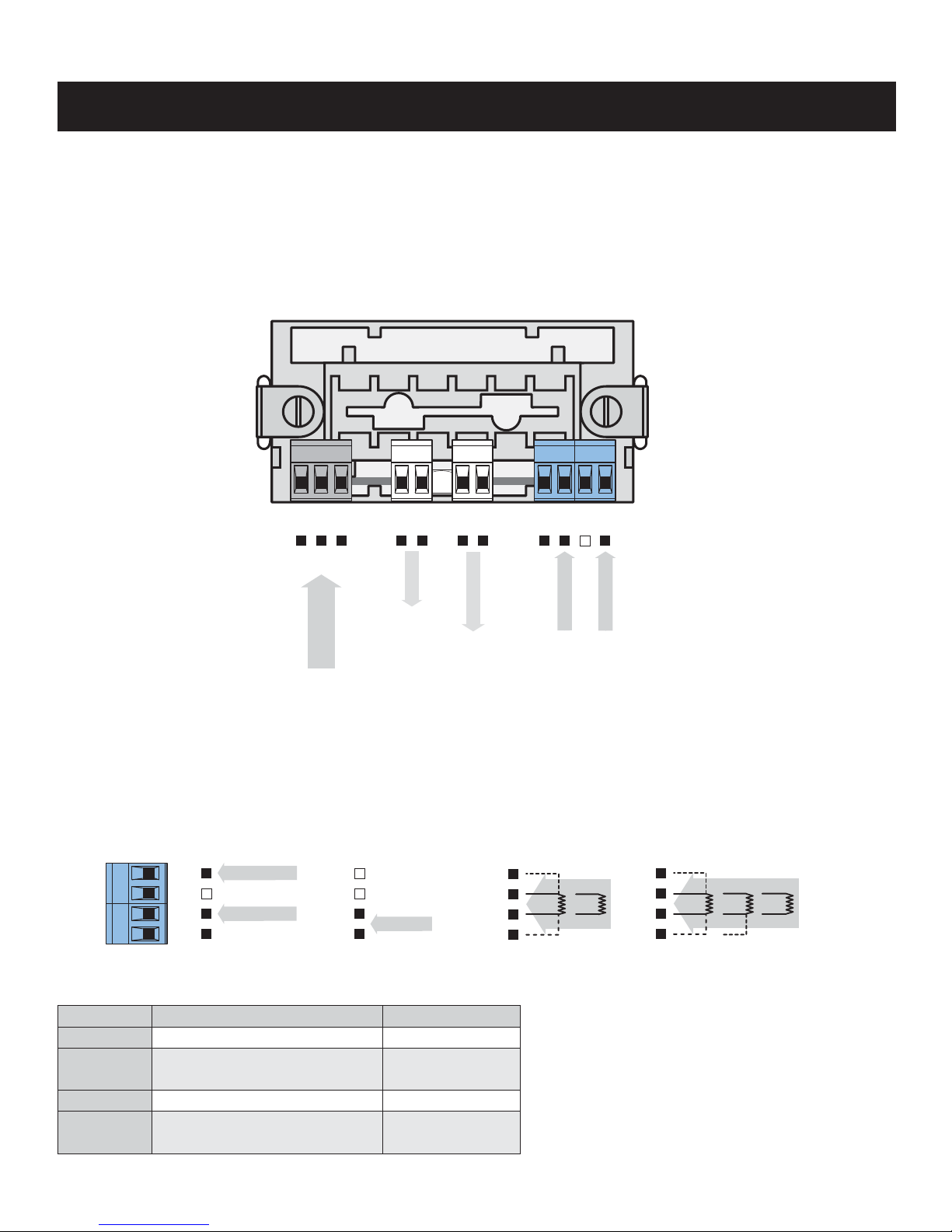
3. CONNECTION
3. CONNECTION
The supply lead for feeding the instrument should not be in the proximity of low-potential signals.
Contactors, motors with larger input and other efficient elements should not be in the proximity of the instrument.
The lead into the instrument input (the measured quantity) should be in sufficient distance from all power leads and appliances.
Provided this cannot be secured, it is necessary to use shielded leads with connection to ground.
The instruments are tested in compliance with standards for use in industrial area, yet, we recommend to abide by the above
mentioned principles.
OM 36OHM OM 36PM OM 36AC
OM 36DC
OM 36RTD
L
N
E
+
+
- -
+
-
Analog output
POWER SUPPLY
INPUT 1
Excitation
2 3 1
+
-
+
INPUT 2
4 5 6 7
GND
8 9 10 11
INPUT 1
INPUT 2
GND
8 9 10 11
E+
S-
E-
S+
ES- ES+
INPUT
+
-
E+
S-
E-
S+
E-
ES+ ES-
ES+ S-
MEASURING RANGE
Type Input 1 Input 2
OM 36 DC - U
±199,9 mV; ±1,999 V; ±19,99 V ±199,9 V; ±300 V
OM 36 DC - I
±199,9 νA ±1,999 mA; ±19,99 mA
±199,9 mA, ±1,999 A; ±5,00 A
OM 36 AC - U
0…199,9 mV; 0…1,999 V; 0…19,99 V 0…199,9 V; 0…300 V
OM 36 AC - I
0…1,999 mA; 0…19,99 mA; 0…199,9 mA
0…1,999 A; 0…5,00 A
 Loading...