


1
OM 36
3 1/2 DIGIT
DC VOLTMETER/AMMETER
AC VOLTMETER/AMMETER
PROCESS MONITOR
OHMMETER
THERMOMETER FOR PT 100
GUARANTEE
YERS
2
INSTRUCTIONS FOR USE - OM 36
SAFETY INSTRUCTIONS
Please, read the enclosed safety instructions carefully and observe them!
These instruments should be safeguarded by isolated or common fuses (breakers)!
For safety information the EN 61 010-1 + A2 standard must be observed.
This instrument is not explosion-safe!
TECHNICAL DATA
Measuring instruments of the OM 36 series conform to European regulation 89/336/EWG and Ordinance 168/1997
Coll.
They are up to the following European standards:
EN 55 022, class B
EN 61000-4-2, -4, -5, -6, -8, -9, -10, -11
The instruments are applicable for unlimited use in agricultural and industrial areas.
CONNECTION
Power supply from the main line has to be isolated from the measuring leads.
ORBIT MERRET, spol. s r.o.
Vodňanská 675/30
198 00 Praha 9
Czech Republic
Tel: +420 - 281 040 200
Fax: +420 - 281 040 299
e-mail: orbit@merret.cz
www.orbit.merret.cz

3
1. CONTENTS
1. Contents . . . . . . . . . . . . . . . . . . . . . . . . . . . . . . . . . . . . . . . . . . . . . . . . . . . . . . . . . . . . . . . . . . . . . . . . . . . . . . . . . . . . .3
2. Instrument description . . . . . . . . . . . . . . . . . . . . . . . . . . . . . . . . . . . . . . . . . . . . . . . . . . . . . . . . . . . . . . . . . . . . . . . . . . . . . .4
3. Connection . . . . . . . . . . . . . . . . . . . . . . . . . . . . . . . . . . . . . . . . . . . . . . . . . . . . . . . . . . . . . . . . . . . . . . . . . . . . . . . . . . . . .5
4. Setting . . . . . . . . . . . . . . . . . . . . . . . . . . . . . . . . . . . . . . . . . . . . . . . . . . . . . . . . . . . . . . . . . . . . . . . . . . . . . . . . . . . . .6
Setting the decimal point . . . . . . . . . . . . . . . . . . . . . . . . . . . . . . . . . . . . . . . . . . . . . . . . . . . . . . . . . . . . . . . . . . . . . . . . . . . . . . . 6
4.1 Change of projection on the display . . . . . . . . . . . . . . . . . . . . . . . . . . . . . . . . . . . . . . . . . . . . . . . . . . . . . . . . . . . . . . . . . . 7
4.2 Setting the excitattion . . . . . . . . . . . . . . . . . . . . . . . . . . . . . . . . . . . . . . . . . . . . . . . . . . . . . . . . . . . . . . . . . . . . . . . . . . . . . 10
5. Technical data . . . . . . . . . . . . . . . . . . . . . . . . . . . . . . . . . . . . . . . . . . . . . . . . . . . . . . . . . . . . . . . . . . . . . . . . . . . . . . . . . . . .12
6. Instrument dimensions and installation . . . . . . . . . . . . . . . . . . . . . . . . . . . . . . . . . . . . . . . . . . . . . . . . . . . . . . . . . . . . . . .13
7. Declaretion of conformity . . . . . . . . . . . . . . . . . . . . . . . . . . . . . . . . . . . . . . . . . . . . . . . . . . . . . . . . . . . . . . . . . . . . . . . . . .14
8. Certificate of guarantee . . . . . . . . . . . . . . . . . . . . . . . . . . . . . . . . . . . . . . . . . . . . . . . . . . . . . . . . . . . . . . . . . . . . . . . . . . . .15
1. CONTENTS

4
INSTRUCTIONS FOR USE - OM 36
2. INSTRUMENT DESCRIPTION
DESCRIPTION
The OM 36 model series are simple 3 1/2 digit panel instruments, which are manufactured in the following alternatives:
DC DC voltmeter/ammeter
AC AC voltmeter/ammeter
PM Process monitor
OHM Ohmmeter
RTD Thermometer for sensors Pt 100
The instrument is based on a simple converter, which secures high accuracy and stability.
ADJUSTABLE DISPLAY PROJECTION
Setting by potentiometers under the front panel (in the range of approx. ±10 %)
Projection ±1999
OPERATION
The instrument is designed for simple measurement without further control.
Placement of the decimal point is selectable by shorting link under the front panel.
EXTENSION
Excitation is suitable for feeding of sensors and transducers. It has a galvanic isolation with continuously adjustable value
in the range of 2...24 VDC.
Analogue outputs will find their place in applications where further evaluating or processing of measured data in external
devices is required. We offer several types of current or voltage non-isolated outputs. The value of analogue output corresponds with the input signal.
5
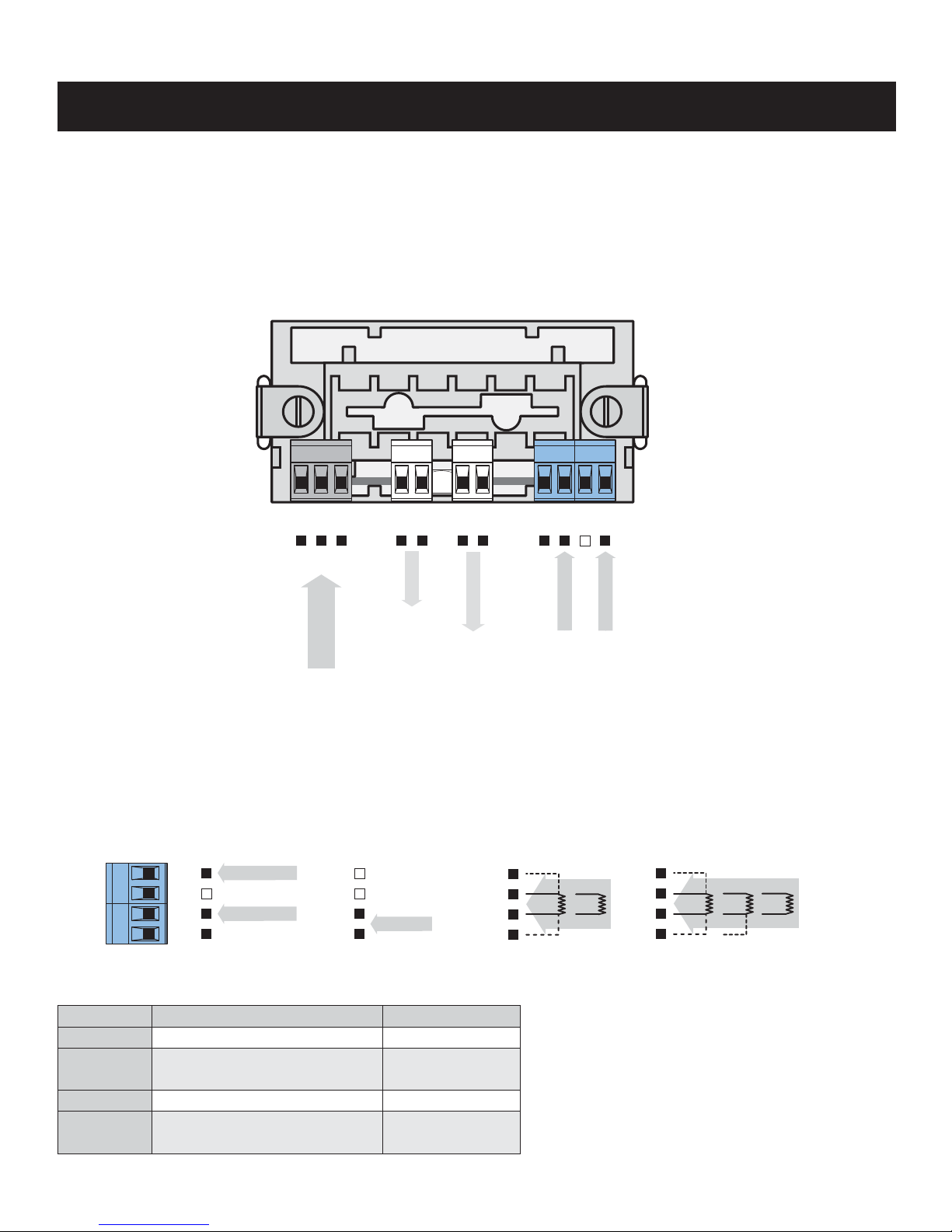
3. CONNECTION
3. CONNECTION
The supply lead for feeding the instrument should not be in the proximity of low-potential signals.
Contactors, motors with larger input and other efficient elements should not be in the proximity of the instrument.
The lead into the instrument input (the measured quantity) should be in sufficient distance from all power leads and appliances.
Provided this cannot be secured, it is necessary to use shielded leads with connection to ground.
The instruments are tested in compliance with standards for use in industrial area, yet, we recommend to abide by the above
mentioned principles.
OM 36OHM OM 36PM OM 36AC
OM 36DC
OM 36RTD
L
N
E
+
+
- -
+
-
Analog output
POWER SUPPLY
INPUT 1
Excitation
2 3 1
+
-
+
INPUT 2
4 5 6 7
GND
8 9 10 11
INPUT 1
INPUT 2
GND
8 9 10 11
E+
S-
E-
S+
ES- ES+
INPUT
+
-
E+
S-
E-
S+
E-
ES+ ES-
ES+ S-
MEASURING RANGE
Type Input 1 Input 2
OM 36 DC - U
±199,9 mV; ±1,999 V; ±19,99 V ±199,9 V; ±300 V
OM 36 DC - I
±199,9 νA ±1,999 mA; ±19,99 mA
±199,9 mA, ±1,999 A; ±5,00 A
OM 36 AC - U
0…199,9 mV; 0…1,999 V; 0…19,99 V 0…199,9 V; 0…300 V
OM 36 AC - I
0…1,999 mA; 0…19,99 mA; 0…199,9 mA
0…1,999 A; 0…5,00 A

6
INSTRUCTIONS FOR USE - OM 36
4. INSTRUMENT SETTING
ADJUSTING ELEMENTS
after removing the top cover frame the following settings are accessible
decimal point - may be adjusted by shorting links
P1 setting the display brightness
P2 setting the zero
- in the DC and AC types it does not always have to be fixed
- in the RTD and OHM types this trimmer is used for compensation of conduct resistance
P3 setting the full range
- nastavení zobrazení displeje (cca ±10 %)
X1 setting the decimal point
- by jumper
X2 setting the measuring rate
- by jumper
1 - 1 X.xxx
2 - 2 XX.xx
3 - 3 XXX.x
Jumper X1, Decimal point
1
3
X2
P1
P2
P3
X1
1 - 2 1,2 m/s
5 - 6 2,5 m/s
2 - 3 5 m/s
5 - 4 10 m/s
Jumper X2, measuring rate
1
3 4
6

7
4. INSTRUMENT SETTING
4.1 CHANGE OF PROJECTION ON THE DISPLAY
The measuring range and projection of the display are set from manufacture pursuant to customer requirements stated in the
order form for which the manufacturer declares validity of the catalogue technical parameters.
Under certain conditions, i.e. the expertise and technical equipment, the change in instrument parameters may be performed
pursuant to the following procedure.
SOLDERING JUMPERS
Type Range Counting the input divider J1 J2 J3 J4
I < 90 mA Shunt R
7
with loss 200 mV or resistances R8, R
11
link link
I < 5 A R
8
, R11 for shunt R7 - loss 200 mV link
U < 200 mV Set by changing R
8
= 750 Ohm, without R8, R
11
link
U < 60 V R8, R
11
U < 300 V R1, R8, R9 remove link B
Pt 100 Without R
1
, R7, R11, remove link A cut link
WIRING DIAGRAM
MIN
R38
2k
J12
1
2
3
R3
R4
82k
82k
+UR
-UR
R5
short
J11
1
2
OFFSET
1k
56k
R14
R23
R24
4k7
MAX
+UR
PROJECTION
DISPLAY
I
N
4
ANALOGUE
DISPLAY
1
2
J4
1
1
1
1
1
2
2
2
2
2
J8
J3
J1
J2
J3
R7
shunt
R20
13R1
Voltage input
R9
Rvar
R8
Rvar
R10
Rvar
R1
1
Rvar
R1
Rvn
Pt 100/Resistance input
INPUT
11
X20
Connection of side input card
I
N
3
I
N
2
I
N
1
O
U
T
C
O
M
+
5
V
G
N
D
5
V
O
F
F
S
O
R
E
F
A
VCC
VBB
When using input card
link A must be disconnected!
10
8
9
Current input

8
INSTRUCTIONS FOR USE - OM 36
CHANGE OF PROJECTION RANGE
Voltage Input < 60 V
- R
8
has value of 1MOhm
Voltage Input > 60 V
- R
8
has value of 1,22 MOhm, 2x 511 kOhm in series
Current Input
Zero offset
R
8
may be replaced by series/parallel combination of two resistances R8 a R
9
R10 may be replaced by series/parallel combination of two resistances R10 a R
11
ZERO OFFSET - SOLDERING JUMPERS
Jumper Offset
J11 - link none
J12 - link, to connector negative
J12 - link, to display positive
R8 x (D
max
- D
min
)
10 000 x (U
max
- U
min
) - (D
max
- D
min
)
R
10
=
R1 x (D
max
- D
min
)
10 000 x (U
max
- U
min
) - (D
max
- D
min
)
R
10
=
D
max
- D
min
10 000 x (I
max
- I
min
)
R
7
=
P
od
Pdo - P
od
R5 = 2 000 x
24 600 000
Pdo - P
od
R3 =
- 2 000 - R
5
R8 x R
9
R8 + R
9
R8 =
R10 x R
11
R10 + R
11
R10 =

9
LEGEND
R8, 9 and R10 ,11 resistances of input divider for range < 60 V
R1 and R8, 9 resistances of input divider for range > 60 V
R
3(4), 5
resistances for zero offset, R5 is, as a standard, replaced by short-circuit
Pod, Pdo offset values (in divisions 0…1999) for extreme positions of the potentiometer „ MIN“
U
min
minimum value of input voltage (in Volts)
U
max
maximum value of input voltage (in Volts)
D
min
minimum value on display (in divisions)
D
max
maximum value on display (in divisions)
I
min
minimum value of input current (in Amperes)
I
max
maximum value of input current (in Amperes)
X6
Excitation
4. INSTRUMENT SETTING

10
INSTRUCTIONS FOR USE - OM 36
4.2 SETTING THE EXCITATION
Excitation is, as a standard, set for 24 VDC.
Change in adjustment of the excitation value is performed by trimmer located over the terminal boards of the instrument (see
picture).
231 4 5
891011
Excitation

11
4. INSTRUMENT SETTING

12
INSTRUCTIONS FOR USE - OM 36
MEASURING RANGE
the range is fi xed, according to order DC
±199,9 mV 1 MOhm Input 1
±1,999 V 1 MOhm Input 1
±19,99 V 1 MOhm Input 1
±199,9 V 1 MOhm Input 2
±300 V 2 MOhm Input 2
±199,9 μA < 260 mV Input 1
±1,999 mA < 260 mV Input 1
±19,99 mA < 260 mV Input 1
±199,9 mA < 200 mV Input 1
±1,999 A < 200 mV Input 1
±5,00 A <50 mV Input 1
the range is fi xed, according to order AC
0…199,9 mV 1 MOhm Input 1
0…1,999 V 1 MOhm Input 1
0…19,99 V 1 MOhm Input 1
0…199,9 V 1 MOhm Input 2
0…300 V 2 MOhm Input 2
0…1,999 mA < 260 mV Input 1
0…19,99 mA < 260 mV Input 1
0…199,9 mA < 200 mV Input 1
0…1,999 A < 200 mV Input 1
0…5,00 A < 50 mV Input 1
Frequency range: 40…2 500 Hz
the range is fi xed, according to order PM
0...5 mA < 260 mV
0...20 mA < 260 mV
4...20 mA < 260 mV
±2 V 1 MOhm
±5 V 1 MOhm
±10 V 1 MOhm
the range is fi xed, according to order OHM
0...199,9 Ohm
0...1,999 kOhm
0...19,99 kOhm
5...105 Ohm
Connection: 2 or 4 wire
the range is fi xed, according to order RTD
Pt xxx ±199,9°C or -200°...850°C
Type Pt: 100/500/1 000 Ohm, platinum, 3850 ppm
Connection: 2, 3 or 4 wire
PROJECTION
Display: ±1999, red or green LED, digit height 14 mm
Decimal point: adjustable by jumper
Brightness: adjustable by potentiometer under the front panel
INSTRUMENT ACCURACY
TC: 100 ppm/°C
Accuracy: ±0,1 % of range
±0,3 % of range (< 100 Hz, crest faktor 1-2) AC
±0,2 % z range OHM
Resolution: 0,1° or 1°C RTD
Rate: 1,2 - 2,5 - 5 - 10 measurements/s
Overload capacity: 10x (t < 100 ms) - not for 5 A and 300 V
2x (long-term)
Calibration: at 25°C and 40 % r.h.
ANALOGUE OUTPUTS
Type: non-isolated,
the output corresponds with the input signal
Nonlinearity: 0,3 % of range
TC: 100 ppm/°C
Rate: response to change of value < 100 ms
Voltage: 0…2 V, 0…5 V, 0…10 V
Current: 0…5/20 mA/4…20 mA
- compensation of conduct up to 600 Ohm
EXCITATION DC/AC/PM
Adjustable: 2...24 VDC/50 mA, isolated
POWER SUPPLY
24/110/230 VAC, 50/60 Hz, 5 VA, ±10%
12...24 VDC, max. 150 mA
12...30 VDC, max. 300 mA, isolated
MECHANIC PROPERTIES
Material: Noryl GFN2 SE1, incombustible UL 94 V-I
Dimensions: 96 x 48 x 110 mm
Panel cut-out: 92 x 45 mm
OPERATING CONDITIONS
Connection: con. terminal board, conductor section up to 2,5 mm
2
Stabilization period: within 15 minutes after switch-on
Working temp.: 0°…50°C
Storage temp.: -10°…85°C
Shielding: IP42, upon request IP64 - front panel only
Construction: safety class I
Overvoltage cat.: EN 61010-1, A2
III. - instrument power supply (300 V)
II. - input, output, excitation (300 V)
for pollution degree II
EMC: EN 61000-3-2+A12; EN 61000-4-2, 3, 4, 5, 8, 11;
EN 550222, A1, A2
5. TECHNICAL DATA

13
6. INSTRUMENT DIMENSIONS
6. INSTRUMENT DIMENSIONS
96 mm
48 mm
Panel cut
Panel thickness: 0,5...8 mm
Side view
Front view
92 mm
45 mm
8 mm
110 mm

14
INSTRUCTIONS FOR USE - OM 36
7. DECLARATION OF CONFORMITY
Company: ORBIT MERRET, spol.s r.o. (Ltd.)
Klánova 81/141
142 00 Prague 4
Czech Republic
IDNo: 00551309
Manufactured: ORBIT MERRET, spol.s r.o. (Ltd.)
Vodňanská 675/30
198 00 Prague 9
Czech Republic
declares at its full responsibility that the product presented hereunder meets all technical requirements, is safe for use when
utilised under the terms and conditions determined by ORBIT MERRET, spol.s r.o. and that our company has taken all measures
to ensure conformity of all products of the type listed hereunder, which are being brought out to the market, with technical
documentation and requirements of the appurtenant statutory orders.
Product: 3 1/2 - digit programmable panel instrument
Type: OM 36, in versions: DC, AC, PM, OHM, RTD
Mode of asses. of conformity: §12, par. 4 b, d of Act No.22/1997 Sb.
Conformity is assessed pursuant to the following standards::
Electrical safety: EN 61010-1
EMC: EN 50131-1, par. 14 and par. 15
EN 55022
EN 61000-3-2 + A12, Cor. 1, change A1, change A2
EN 61000-4-2
EN 61000-4-3
EN 61000-4-4
EN 61000-4-5
EN 61000-4-6
EN 61000-4-8
EN 61000-4-11, par. 5.1 and par. 5.2
and government ordinance:
Electrical safety: No. 168/1997 Sb.
EMC: No. 169/1997 Sb.
The evidence are the protocols of authorized and accredited organization:
VTÚE Praha, experimental laboratory No. 1158 accredited by ČIA, o.p.s. with EN ISO/IEC 17025
Place and date of issue: Prague, 14. januar 2001 Miroslav Hackl
Company representative

15
8. CERTIFICATE OF GUARANTEE
Product OM 36 DC AC PM OHM RTD
Type . . . . . . . . . . . . . . . . . . . .
Manufacturing No. . . . . . . . . . . . . . . . . . . . .
Date of sale . . . . . . . . . . . . . . . . . . . .
A guarantee period of 24 months from the date of sale to the user applies to this instrument.
Defects occuring during this period due to manufacture error or due to material faults shall be eliminated free of charge.
For instrument quality, function and construction the guarantee shall apply provided that the instrument was connected and
used in compliance with the instruction for use.
The guarantee shall not apply for defects caused by:
- mechanic damage
- in transport
- intervention of unqualified person incl. the user
- unavoidable event
- other unprofessional interventions
The manufacturer performs the guarantee and post-guarantee repairs unless provided for otherwise.
Stamp, signature
8. CERTIFICATE OF GUARANTEE
transport
navoidable event
performs the g
instrument.
s
e
ri
o
d
u
a
n
c
h
a
- m
- in
- in
- u
- o
r
i
n
tru
instruction for use.
unction and construction the guarantee shall apply provided that the i
s the guarantee and post-guarantee repairs unless provided for othe
tamp, signature
. . .
. . .
ARANTEE
. . . . . . . . . . . . . . .
.
. . . . . . . . . . . . .
S
YE
R
R

16
INSTRUCTIONS FOR USE - OM 36
TECHDOK - OM 36 - 2008 - 6v1 - en
Austria
ING.E. GRUBER GmbH
Edu. Kittenberger Gasse 97 Top2
A-1230 Wien
tel: +43 - 1 - 869 23 39-0
fax: +43 - 1 - 865 18 75
e-mail: office@gruber-components.at
www.gruber-components.at
The Netherlands
AE SENSORS B.V.
J. Valsterweg 92
3301 AB Dordrecht
tel: +31 - 78 - 621 31 52
fax: +31 - 78 - 621 31 46
e-mail: aesensors@aesensors.nl
www.aesensors.nl
Slovakia
TECHREG, s.r.o.
Dukelských hrdinov 2
984 22 Lučenec
tel: +421 - 47 - 433 15 92
fax: +421 - 47 - 433 15 92
e-mail: techreg@bb.psg.sk
www.techreg.sk
USA
METRIX Instruments Co.
1711 Townhurst Dr.
Houston, Texas 77043-2899
tel: +1 - 713 - 461 21 31
fax: +1 - 713 - 461 82 83
e-mail: sales@metrix1.com
www.metrix1.com
Germany
MEGATRON Elektronik AG & Co.
Hermann-Oberth-Str. 7
85640 Putzbrunn/München
tel: +49 - 89 - 460 94 - 0
fax: +49 - 89 - 460 941 01
e-mail: sales@megatron.de
www.megatron.de
Russian Federation
РОCПРИБОР ЗАО
Россия, 111 033, Краснодар
ул. Авиамоторная, 50
тел.: (495) 960 28 32
факс: (495) 428 46 75
e-mail: sales@rospribor.ru
www.rospribor.ru
Switzerland
ORBIT CONTROLS AG
Zürcherstrasse 137
8952 Schlieren
tel: +41 - 1 - 730 27 53
fax: +41 - 1 - 730 27 83
e-mail: info@orbitcontrols.ch
www.orbitcontrols.c
Lithuania
RIFAS UAB
Tinklu g. 29a
LT-5300 Panevéžys
tel: +370 - 5 - 510 400
fax: +370 - 5 - 582 729
e-mail: sales@metrix1.com
www.metrix1.com
Russian Federation
ПО Интерфейс
Россия, 350020, Краснодар
ул.Шоссе Нефтяников, 9/1
тел.: (861) 215 41 44
факс: (861) 215 41 44
e-mail: import@bk.ru
www.orbit.merret.ru
Ukraine
OOO <KOTRIS>
Nesterova 3, Office 907
030 57 Kyjev
tel: +44 - 446 - 21 42
fax: +44 - 446 - 21 42
e-mail: metrix-ua@svitonline.com
ORBIT MERRET, spol. s r.o.
Vodnanska 675/30
198 00 Prague 9
Czech Republic
tel: +420 - 281 040 200
fax: +420 - 281 040 299
e-mail: orbit@merret.cz
www.orbit.merret.cz
 Loading...