

GUARANTEE
YERS
OM 351
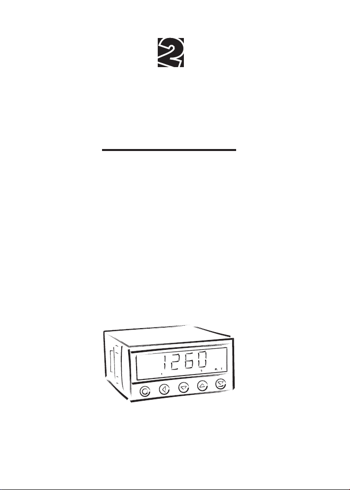
3 1/2 DIGIT PROGRAMMABLE
DC VOLTMETER/AMMETER
AC VOLTMETER/AMMETER
PROCESS MONITOR
THERMOMETER FOR PT 100/500/1 000
THERMOMETER FOR NI 1 000
THERMOMETER FOR THERMOCOUPLES
DISPLAY INST. FOR LIN. POTENTIOMETERS
OHMMETER
1

INSTRUCIONS FOR USE OM 351
SAFETY INSTRUCTIONS
Please, read the enclosed safety instructions carefully and observe them!
These instruments should be safeguarded by isolated or common fuses (breakers)!
For safety information the EN 61 010-1 + A2 standard must be observed.
This instrument is not explosion-safe!
TECHNICAL DATA
Measuring instruments of the OM 351 series conform to the European regulation 89/336/EWG and the Ordinance
168/1997 Coll.
They are up to the following European and Czech standards:
CNS EN 55 022, class B
CNS EN 61000-4-2, -4, -5, -6, -8, -9, -10, -11
The instruments are applicable for unlimited use in agricultural and industrial areas.
CONNECTION
Supply of energy from the main line has to be isolated from the measuring leads.
ORBIT MERRET, spol. s r.o.
Vodnanska 675/30
198 00 Prague 9
Czech Republic
Tel: +420 - 281 040 20 0
Fax: +420 - 281 040 299
e-mail: orbit@merret.cz
www.orbit.merret.cz
2

1. CONTENTS
1. CONTENTS
1. Contents . . . . . . . . . . . . . . . . . . . . . . . . . . . . . . . . . . . . . . . . . . . . . . . . . . . . . . . . . . . . . . . . . . . . . . . . . . . . . . . . . . . . 3
2. Instrument description . . . . . . . . . . . . . . . . . . . . . . . . . . . . . . . . . . . . . . . . . . . . . . . . . . . . . . . . . . . . . . . . . . . . . . . . . . . . . 4
3. Connection . . . . . . . . . . . . . . . . . . . . . . . . . . . . . . . . . . . . . . . . . . . . . . . . . . . . . . . . . . . . . . . . . . . . . . . . . . . . . . . . . . . . 6
4. Setting . . . . . . . . . . . . . . . . . . . . . . . . . . . . . . . . . . . . . . . . . . . . . . . . . . . . . . . . . . . . . . . . . . . . . . . . . . . . . . . . . . . . 8
Programming modes . . . . . . . . . . . . . . . . . . . . . . . . . . . . . . . . . . . . . . . . . . . . . . . . . . . . . . . . . . . . . . . . . . . . . . . . . . . . . . . 8
Control keys functions . . . . . . . . . . . . . . . . . . . . . . . . . . . . . . . . . . . . . . . . . . . . . . . . . . . . . . . . . . . . . . . . . . . . . . . . . . . . . . 8
Setting the DP and the (-) sign. . . . . . . . . . . . . . . . . . . . . . . . . . . . . . . . . . . . . . . . . . . . . . . . . . . . . . . . . . . . . . . . . . . . . . . . 9
4.1 Guide through minimum instrument setting, calibration . . . . . . . . . . . . . . . . . . . . . . . . . . . . . . . . . . . . . . . . . . . . . . . . . . . 10
4.2 User menu . . . . . . . . . . . . . . . . . . . . . . . . . . . . . . . . . . . . . . . . . . . . . . . . . . . . . . . . . . . . . . . . . . . . . . . . . . . . . . 12
4.2.1 Internal values resetting (Tare) . . . . . . . . . . . . . . . . . . . . . . . . . . . . . . . . . . . . . . . . . . . . . . . . . . . . . . . . . . . . . . . 12
4.2.2 Setting the limits . . . . . . . . . . . . . . . . . . . . . . . . . . . . . . . . . . . . . . . . . . . . . . . . . . . . . . . . . . . . . . . . . . . . . . . . . . . 13
4.2.3 Setting the display brightness . . . . . . . . . . . . . . . . . . . . . . . . . . . . . . . . . . . . . . . . . . . . . . . . . . . . . . . . . . . . . . . . 13
4.3 Configuration menu . . . . . . . . . . . . . . . . . . . . . . . . . . . . . . . . . . . . . . . . . . . . . . . . . . . . . . . . . . . . . . . . . . . . . . . . . . . . . . 14
4.3.1 Configuration mode - INPUT
4.3.1.1 Internal values resetting (TARE). . . . . . . . . . . . . . . . . . . . . . . . . . . . . . . . . . . . . . . . . . . . . . . . . . . . . 15
4.3.1.2 Setting the measuring range, displacement, compensation and measuring rate. . . . . . . . . . . . . . . 16
4.3.1.3 Setting the external control input. . . . . . . . . . . . . . . . . . . . . . . . . . . . . . . . . . . . . . . . . . . . . . . . . . . . 18
4.3.1.4 Setting functions of the control key (ENTER) . . . . . . . . . . . . . . . . . . . . . . . . . . . . . . . . . . . . . . . . . . . 19
4.3.2 Configuration mode - CHANNELS
4.3.2.1 Projection on the display (MIN, MAX) . . . . . . . . . . . . . . . . . . . . . . . . . . . . . . . . . . . . . . . . . . . . . . . 20
4.3.2.2 Setting the digital filters . . . . . . . . . . . . . . . . . . . . . . . . . . . . . . . . . . . . . . . . . . . . . . . . . . . . . . . . . . . 21
4.3.2.3 Setting the decimal point . . . . . . . . . . . . . . . . . . . . . . . . . . . . . . . . . . . . . . . . . . . . . . . . . . . . . . . . . . 21
4.3.3 Configuration mode - OUTPUT
4.3.3.1 Cofiguration and setting the limits . . . . . . . . . . . . . . . . . . . . . . . . . . . . . . . . . . . . . . . . . . . . . . . . . . . 22
4.3.3.2 Setting the data output . . . . . . . . . . . . . . . . . . . . . . . . . . . . . . . . . . . . . . . . . . . . . . . . . . . . . . . . . . . 23
4.3.3.3 Setting the analog output . . . . . . . . . . . . . . . . . . . . . . . . . . . . . . . . . . . . . . . . . . . . . . . . . . . . . . . . . 23
4.3.3.4 Setting the display brightness . . . . . . . . . . . . . . . . . . . . . . . . . . . . . . . . . . . . . . . . . . . . . . . . . . . . . . 24
4.3.4 Configuration mode - SERVICE
4.3.4.1 Setting the menu access - resetting and limits . . . . . . . . . . . . . . . . . . . . . . . . . . . . . . . . . . . . . . . . . . 26
4.3.4.2 Restoration of the manufacture setting . . . . . . . . . . . . . . . . . . . . . . . . . . . . . . . . . . . . . . . . . . . . . . . 27
4.3.4.3 Calibration of the input range (DU) . . . . . . . . . . . . . . . . . . . . . . . . . . . . . . . . . . . . . . . . . . . . . . . . . 28
4.3.4.4 Setting new access password . . . . . . . . . . . . . . . . . . . . . . . . . . . . . . . . . . . . . . . . . . . . . . . . . . . . . . 28
4.3.4.5 Instrument identification . . . . . . . . . . . . . . . . . . . . . . . . . . . . . . . . . . . . . . . . . . . . . . . . . . . . . . . . . . . 28
5. Method of measuring of the cold junction . . . . . . . . . . . . . . . . . . . . . . . . . . . . . . . . . . . . . . . . . . . . . . . . . . . . . . . . . . . . 30
6. Data protocol . . . . . . . . . . . . . . . . . . . . . . . . . . . . . . . . . . . . . . . . . . . . . . . . . . . . . . . . . . . . . . . . . . . . . . . . . . . . . . . . . . . 32
7. Error statements . . . . . . . . . . . . . . . . . . . . . . . . . . . . . . . . . . . . . . . . . . . . . . . . . . . . . . . . . . . . . . . . . . . . . . . . . . . . . . . . . 34
8. Technical data. . . . . . . . . . . . . . . . . . . . . . . . . . . . . . . . . . . . . . . . . . . . . . . . . . . . . . . . . . . . . . . . . . . . . . . . . . . . . . . . . . . 36
9. Instrument dimensions and installation . . . . . . . . . . . . . . . . . . . . . . . . . . . . . . . . . . . . . . . . . . . . . . . . . . . . . . . . . . . . . . 38
10. Certificate of guarantee . . . . . . . . . . . . . . . . . . . . . . . . . . . . . . . . . . . . . . . . . . . . . . . . . . . . . . . . . . . . . . . . . . . . . . . . . . . 39
3

INSTRUCIONS FOR USE OM 351
2. INSTRUMENT DESCRIPTION
DESCRIPTION
The OM 351 model series are 3 1/2 digit programmable panel instruments, manufactured in the following
alternatives:
OM 351DC DC voltmeter/ammeter
OM 351AC AC voltmeter/ammeter
OM 351PM Process monitor
OM 351RTD Thermometer for Pt 100/500/1 000, Ni 1 000
OM 351T/C Thermometer for thermocouples
OM 351DU Display instrument for linear potentiometers
OM 351OHM Ohmmeter
The instruments are based on an 8-bit microcontroller with A/D converter, that secures high accuracy, stability and
easy operation of the instrument.
Programmable projection of the display
Calibration projection for the beginning and the end of the output range
setting the output type
Projection ±1999
Digital filters
Radius of insensitiveness adjustable in process units
Exponential average from 2…100 measurements
Mathematic functions
Tare* assigned to reset the display in case of non-zero input signal
External control
Hold display/instrument blocking
Lock locking the control keys or the access into Configuration menu
Tare tare activation
4
* only for types DC, PM, DU

2. INSTRUMENT DESCRIPTION
OPERATION
The instrument is set and controlled by five control keys located on the front panel. All programmable settings of the
instrument are realized in two adjusting modes:
Configuration menu (hereinafter referred to as „CM“) is protected by an optional number code and contains
complete instrument setting
User menu may contain arbitrary programming settings, defined in „CM“ with another selective restric
tion (see, change)
All programmable parameters are stored in the EEPROM memory (they hold even after the instrument is switched
off).
EXTENSION
Excitation is suitable for feeding sensors and converters. It has a galvanic isolation of 15 VDC.
Comparators are assigned to control two limit values with relay output. The limits have adjustbale hysteresis as
well as selectable delay of the switch-on. Reaching the preset limits is signalled by LED and simultaneously by the
switch-on of the relevant relay.
Data outputs are for their rate and accuracy suitable for transmission of the measured data for further projection or
directly into the control systems. We offer an isolated RS 232 and RS 485 with the ASCII protocol.
Analogue outputs will find their place in applications where further evaluating or processing of measured data
in external devices is required. We offer universal analog output with the option of selection of the type of output
- voltage/current. The value of analog output corresponds with the displayed data and its type and range are
selectable in the programming mode.
* only for type T/C
5

INSTRUCIONS FOR USE OM 351
232
485
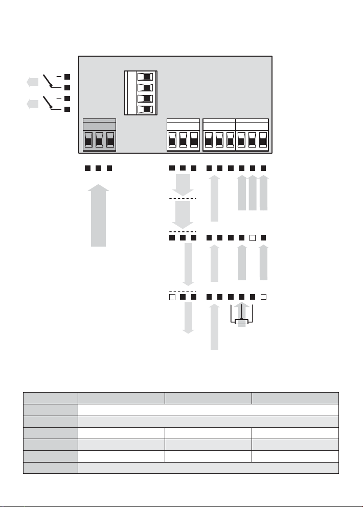
3. CONNECTION
The lead for feeding the instrument should not be in the proximity of the incoming low-potential signals.
Contactors, motors with larger input power and other efficient elements should not be in the proximity of the instru-
ment.
The lead into the input of the instrument (the measured quantity) should be in sufficient distance from all power leads
and appliances. Provided this cannot be secured it is necessary to use shielded leads with connection to ground.
The instruments are tested in compliance with standards for use in industrial area, yet we recommend to abide by
the above mentioned principles.
L2
L1
12 3
-
+
L
N
POWER SUPPLY
Grounding on terminal „E“ has to be connected at
all times
In RTD input with 2- or 3-wire connection it is necessary
to link the unconnected inputs (13+14/15+16 or 13+14)
on the terminal block
Relay parameters listed in Technical data apply for
resistance load. Upon connection of induction load we
recommend fi tting the leads to relay 1 A with a fuse for
protection of maximum load.
6
4567
E
8910
RxD
GND
TxD
232
GND
Rx/Tx-
Rx/Tx+
485
-
+
GND
Analog output
14 15 1611 12 13
-
+
GND
Hold/Lock
INPUT
E-
Hold/Lock
S-
S-
CJC
S+
E+
ES+E-
ES+ES-
OM 351T/C
OM 351RTD, OHM
3. INSTRUMENT CONNECTION
232
485
L2
L1
MEASURING RANGES
12 3
-
+
L
N
POWER SUPPLY
4567
8910
E
GND
GND
GND
TxD
232
Rx/Tx-
485
RxD
Rx/Tx+
-
+
Analog output
-
+
Excitation
14 15 1611 12 13
-
+
+
GND
Hold/Lock/Tare
Hold/Lock
Hold/Lock/Tare
INPUT 1
GND
INPUT 1
z k
INPUT 2
Type Input 1 Input 2 Input 3
OM 351 AC
OM 351 AC
OM 351 DC
OM 351 DC
OM 351 PM
OM 351 OHM
Input 1 > 0…60 mV * 0…150 mV * 0…300 mV * 0…1 A * 0…5 A
Input 2 > 0…10 V * 0…100 V * 0…150 V * 0…250 V * 0…450 V
±2/±20 mA ±0,2/±2 V ±20/±200 V
0…1/5 A 0…60/150 mV
0/4…20 mA 0…2 V 0…5/10 V
0…200 Ohm * 0...2 kOhm * 0...100 kOhm * 5…105 Ohm
+
INPUT 3
INPUT 3
OM 351DC, PM
OM 351AC
OM 351DU
7
INSTRUCIONS FOR USE OM 351
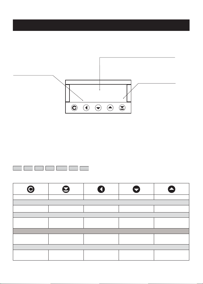
4. INSTRUMENT SETTING
Setting and controlling the instrument is performed through 5 control keys on the front panel. By means of these controls
it is possible to browse through the operating program and to select and set the required values.
Measured value
Relay status
ON the digit is lit
OFF the digit is not lit
OFF the digit is flashing
limits with restriction
(delay)
CONFIGURATION MODE USER MODE
143.7
1T2 M
• designated for professional service and maintenance • designated for instrument service
• complete instrument setting • may contain setting the limits, resetting
• access is password protected the tare and brightness, with restriction as
• authorization for "User mode" per the setting in "Configuration mode"
SYMBOLS USED IN THE INSTRUCTIONS
DC AC PM DU OHM RTD T/C
Indicates the setting for given type of instrument
Function
T Tare
CONTROL KEYS FUNCTIONS
MENU ENTER LEFT DOWN UP
Measuring mode
menu access tare* tare projection*
Moving around in the menu
exit the menu without
saving
Setting/selecting - items
cancel setting without
saving
Setting - numbers
cancel setting without
saving
8
move to next level back to previous level move to next item move to next item
confi rm selected item move down move up
confi rm selected
number
move to higher
decade
change of current
fi gure - down -
change of current
fi gure - up -
* if the function is permitted in CM
4. INSTRUMENT SETTING
SETTING THE DECIMAL POINT AND THE MINUS SIGN
DECIMAL POINT
Its selection in calibration modes, upon modification of the number to be adjusted is performed by the
control key
Positioning is performed by
Setting the decimal point may be performed correctly with the (+/-) signs being turned off.
MINUS SIGN
Setting of the minus sign is performed by the control key on higher decade. When editing the item the subtraction
must be made from the current number (e.g.: 13 >
ACCESS INTO THE CONFIGURATION MODE
with transition behind the highest decade, when the decimal point starts flashing.
/
.
, on class 100 > -87)
.
+
PAS
w/o saving
shift left
0,1,2…
000
9,8,7…
OK
INP.
CHA .
OUT.
SER.
The code from manufacture is always
preset to 000
In case of loss of access password it is possible to
use the universal access code "177"
If the code is preset to 000 than the
access into „CM“ is free, i.e. without call
for its setting
9
INSTRUCIONS FOR USE OM 351
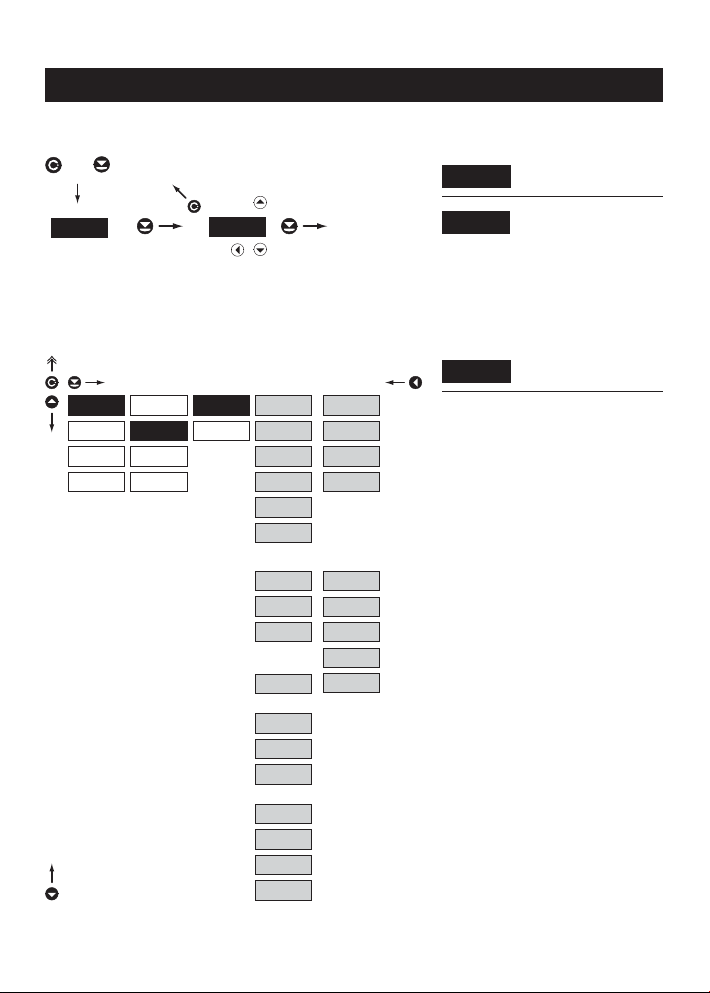
4.1 GUIDE THROUGH MINIMUM INSTRUMENT SETTING
Access into the „Configuration menu“
+
PAS
Selection of the measuring range/input type
INP.
CHA .
OUT.
SER.
CL. T.
CFG
AUX.
KEY
w/o saving
shift left
MOD
M/S
0,1,2…
000
9,8,7…
DC - 1
0. 2 V
2. V
20. V
199. V
2. i
20. i
RTD
2-w
3-w
4-w
T/C
OK
DC - 2
60. m
150. m
1. a
5. a
PM
u 2.
u 5.
u10.
i 0.
i 4.
B
R
S
T
E
J
K
N
password
DC Input
- setting the input range is dependant on the
ordered measuring range
PM Input
- setting the input range
RTD Input
- setting the type of connection
- in case of 2- or 3-wire connection it is
necessary to link the unconnected inputs (see
the connection)
T/C Input
- setting the type of thermocouple is dependant
on the ordered measuring range
- B type B Range 1
R type R Range 2
S type S
T type T
E type E Range 3
J type J
K type K
N type N
Entering the introductory
PAS
access password
Standard manufacture
000
setting of the access
Setting the instrument
MOD
measuring range
10
Setting projection on the display
INP.
CHA.
OUT.
SER.
If the code is preset to 000 than the
access into „CM“ is free, i.e. without call
for its setting
MI N
MAX
FI L .
FOR.
4. GUIDE THROUGH MINIMUM INSTRUMENT SETTING
Setting the display
MI N .
projection for minimum value
of the input signal
- range of the setting is ±1999
value of the input signal
- range of the setting is ±1999
Input type Displayed items of the menu
DC MIN, MAX
PM MIN, MAX
DU MIN, MAX
OHM MIN, MAX, *LEA.
RTD *LEA., r. Ad.
T/C CJC., t. CJ.
* only for 2-wire
Setting the display
MAX
projection for maximum
11

INSTRUCIONS FOR USE OM 351
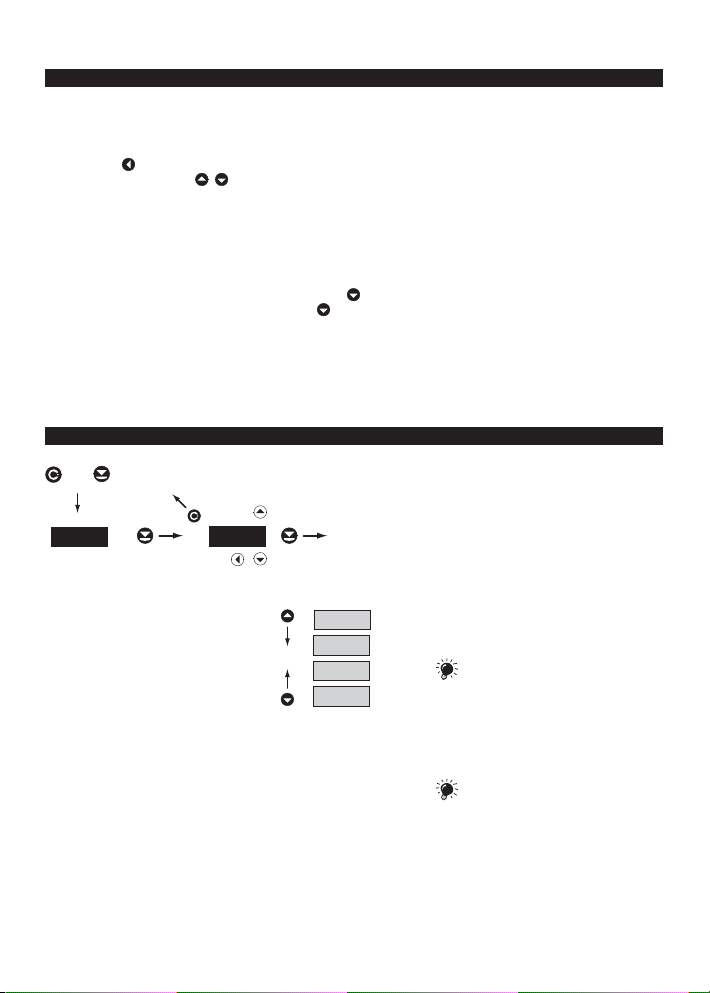
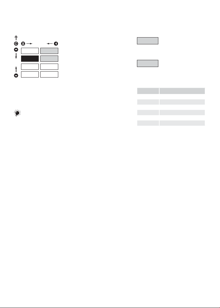
4.2 USER MENU
• designated for instrument service
• may contain setting the limits, analog and data output and brightness, with restriction as per the setting in "Configuration mode"
23.6
INP.
Tare resetting
INP. CL. t..
Tare resetting
OUT. LIM.
Setting limits,
hysteresis and
delay
bri.
Setting the
display brightness
4.2.1 RESETTING THE INTERNAL VALUES
CL. t.INP.
OUT.
Adjustable authorization of access into items,
see page 26
Setting limits and display brightness
Projection of items and their accessability
depends on the setting of access rights in the
„Confi guration menu“
Tare resetting
CL. t .
OUT.
12

4.2.2 LIMITS - ENTERING THE VALUES
INP. LIM
BRi .
Adjustable authorization of access into items,
see page 27
4.2.3 DISPLAY BRIGHTNESS
L 1
L 2
LI M .
HYS.OUT.
Ti m .
4. INSTRUMENT SETTING - CONFIGURATION MODE
Entering the limit values
LI M
for status evaluations
Setting for Limit 1
L 1
Setting for Limit 2
L 2
Setting the limit for relay
LI M .
switch-on
- in full display range
- in full display range
- in range 0…99,9 s
Setting hysteresis only in
HYS.
(+) values
Setting the delayed
ti m .
switch-on of the limit
INP.
OUT.
LI M
BRi..
25%
50%
75%
100%
DEF
Setting the display
BRi .
brightness
- by selecting the display brightness we may
react properly to light conditions in place of
location of the instrument
- brightness in the programming menu is
always 100 %
Display brightness = 25 %
25 %
Display brightness = 50 %
50 %
Display brightness = 75 %
75 %
Display brightness = 100 %
100 %
13

INSTRUCIONS FOR USE OM 351
4.3 CONFIGURATION MENU
• designated for professional service and maintenance
• complete instrument setting
• access is protected by password or a shorting link on the input connector
• authorization for "User mode"
Upon delay longer than 30 s the programming mode is automatically discontinued and the instrument itself switches back to the measuring mode
+
23.6
PAS
000
Entering the access password
INP. CL. t . AUX.
Resetting internal values
CHA . MI N FI L .
Setting projection for min.
input signal
CFG .
Instrument configuration
MAX
Setting projection for max.
input
Auxiliary input
function
Setting digital
filters
OUT. LI M . DAT. A. O .
Setting the
limits, hysteresis
and delay
Setting the data
output
Setting the
analog output
SER. ACC. RES . N. PA .
Setting the
access rights
into „UM“
14
Restoring the
manufacture
setting/
calibration
Instrument
calibration
CAL
KEY
Control-key
function
FOR.
Setting the
decimal point
BRi .
Setting the
display
brightness
Setting
new access
password
Instrument setting
Instrument setting, calibration
Setting the outputs
Service functions, authorization, calibration
Id .
Instrument
identification
INP.
CHA .
OUT.
SER.

4.3.1 CONFIGURATION MODE - INPUT
CL. t.
INP.
CHA .
OUT.
SER.
4.3.1.1 INTERNAL VALUES RESETTING
INP.
CHA .
OUT.
SER.
CFG
AUX.
KEY
CL. t.
CFG
AUX.
KEY
4. INSTRUMENT SETTING - CONFIGURATION MODE
The basic instrument functions are adjusted
in this menu
Internal values resetting
CL. t.
Selecting the measuring
CFG
range and measuring rate
Setting the external control
AUX.
input function
Setting the control-key
KEY
function
Tare resetting
CL. t .
15

INSTRUCIONS FOR USE OM 351
4.3.1.2.1 SET TING THE MEASURING RANGE
CL. T.
INP.
CHA .
OUT.
SER.
CFG
AUX.
KEY
MOD
M/S
199. V
DC - 1
0. 2 V
2. V
20. V
2. i
20. i
RTD
2-w
3-w
4-w
T/C
Setting the instrument
MOD
measuring range
DC - 2
60. m
150. m
1. a
5. a
PM
u 2.
u 5.
u10.
i 0.
i 4.
B
R
S
T
E
J
K
N
PM Input
- setting the input range is dependant on the
ordered mmeasuring range
- 0.2 u ±0,2 V Range 1
2.u ±2 V
20.u ±20 V
199.u ±200 V
60.m ±60 mV Range 2
150.m ±150 mV
1.A ±1 A
5.A ±5 A
PM Input
- setting the input range
- u 2. 0...2 V
u 5. 0...5 V
u 10. 0...10 V
i 0. 0...20 mA
i 4. 4...20 mA
RTD Input
- setting the type of connection
- in case of 2- or 3-wire connection it is
necessary to link the unconnected inputs (see
the connection)
T/C Input
- setting the type of thermocouple is dependant
on the ordered measuring range
- B type B Range 1
R type R Range 2
S type S
T type T
E type E Range 3
J type J
K type K
N type N
16

4. INSTRUMENT SETTING - CONFIGURATION MODE
4.3.1.2.2 SHIFTING THE BEGINNING OF THE RANGE
r. Ad.
CL. t .
INP.
CHA .
OUT.
SER.
4.3.1.2.3 COMPENSATION OF 2-WIRE CONDUCT
INP.
CHA .
OUT.
SER.
4.3.1.2.4 SETTING THE METHOD OF EVALUATION OF THE COLD JUNCTION
INP.
OUT.
SER.
CFG
AUX.
KEY
CL. t .
CFG
AUX.
KEY
CL. t .
CFG
AUX.
KEY
MOD
r. Ad.
LEA .
M/S
MOD
r. Ad.
LEA .
M/S
MOD
CJC
t .C. J .
M/S
YES
In. 1
In. 2CHA .
E. 1
E. 2
- in cases when it is necessary to shift the
beginning of the range by certain value, e.g.
when sensor is used in a measuring head
- entered directly in Ohm
LEA .
- for measurement accuracy it is necessary to
perform compensation of the conduct always
in case of 2-wire connection
- entered directly in Ohm
- prior to confirmation of the displayed
challenge „YES“ it is necessary to substitute
the sensor at the end of the conduct by a
short circuit
- preset from manufacture to „0“
CJC.
- description of the method of evaluation of the
cold junction is in chapter 5, page 30
In.1 .
- cold junction measurement on the instrument
brackets
In. 2.
- cold junction measurement on the instrument
brackets with anti-seris connection of
ref.thermocouple
E.1
- whole measuring set works at the same and
constant temperature
E.2
- upon the use of compensation box
RTD OHM
Shifting the beginning of
the measuring range
RTD OHM
Compensation of 2-wire
conduct
T/C
Method of evaluation of
the cold junction
Measurement without
reference thermocouple
Measurement with reference
thermocouple
Measurement without
reference thermocouple
Measurement with reference
thermocouple
- -
17

INSTRUCIONS FOR USE OM 351
4.3.1.2.5 SETTING THE TEMPERATURE OF THE COLD JUNCTION
CL. t .
INP.
CHA .
OUT.
SER.
4.3.1.2.6 SETTING THE INSTRUMENT MEASURING RATE
INP.
OUT.
SER.
CFG
AUX.
KEY
CL. t.
CFG
AUX.
KEY
MOD
CJC
t .C. J .
M/S
MOD
M.P.S.
1. 2CHA .
5. 0
10 .0
0.5
2.5
DEF
Setting the temperature
t C.J.
of the cold junction
- range 0…98°C with compensation box
The method and the process of setting of
the cold junctions is described in a separate
chapter on page 30
Setting the measuring
M. P.S .
rate
Rate - 0,5 measurements/s
0.5
Rate - 1,2 measurements/s
1. 2
Rate - 2,5 measurements/s
2.5
Rate - 5 measurements/s
5. 0
Rate - 10 measurements/s
10 .0
T/C
4.3.1.3 EXTERNAL INPUT FUNCTION SELECTION
DEF
CL. t.
INP.
CFG
OUT.
SER.
18
AUX.
KEY
LOC .
HLD.CHA .
TAR.
External input function
AUX.
selection
LOCK, locking the control
LOC .
keys on the instrument
HOLD, stop measuring of
HLD.
the entire instrument
TARE - Tare activation
TAR.
* only for types DC, PM, DU

4. INSTRUMENT SETTING - CONFIGURATION MODE
4.3.1.4 SETTING OTHER FUNCTIONS OF THE „ENTER“ KEY
INP.
OUT.
SER.
CL. t.
CFG
AUX.
KEY
DI S .
ENA .CH A.
DEF
Setting other functions of
KEY
the control-key
Without function
DI S .
Activation of keys for tare
EN b .
projection and resetting*
19

INSTRUCIONS FOR USE OM 351
4.3.2 CONFIGURATION MODE - CHANNELS
INP.
CHA.
OUT.
SER.
Mi N
MAX
FI L .
FoR.
In this menu instrument parameters are set
Setting display projection for
Mi N
minimum value of the input
signal
signal
Input type Setting options
DC
AC
PM
DU
OHM
RTD
T/C
T/
Setting display projection for
MAX
maximum value of the input
Setting the digital filters
FI L .
Setting the decimal point
FoR.
C
4.3.2.1 PROJECTION ON THE DISPLAY
INP.
CHA.
OUT.
SER.
20
Mi N
MAX
FI L .
FoR.
DC
AC PM DU
Setting display projection
Mi N.
for minimum value of the
input signal
- range of the setting is ±1999
input signal
- range ot the setting is ±1999
Setting display projection
MAX
for maximum value of the
OHM

4. INSTRUMENT SETTING - CONFIGURATION MODE
4.3.2.2 SETTING THE DIGITAL FILTERS
Setting the digital filters
FI L .
INP. MOD
CHA.
OUT.
SER.
Input
Mi N
MAX
FIL.
FoR.
con .
OFF
EXP .
UNS.
Display
± Filter
Setting the filtration constant
con .
- this menu is always displayed after selection
of a particular type of filter
Filters are off
OFF
Selection of exponential
EXP
filter
- the value is calculated from a number of
measurements selected in „CON“
- range 2…100
- this filter enables to stabilize the resulting
value. A measuring result is understood as the
previous value, provided the meqsured value
is not higher than the previous + P or smaller
than the previous - P. Value „±P“ indicates the
band of insensitiveness in which the measured
value may change without affecting the result
Time
- change of the data on display
- range ±1999
Selection of the band of
UNS.
insensitiveness
4.3.2.3 SETTING THE DECIMAL POINT
DC
AC PM DU
OHM
INP. 000 .
CHA.
OUT.
SER.
Mi N
MAX
FI L .
FoR.
00. 0
0. 00
.000
FL. P.
Setting the decimal point
FoR.
- the instrument allows classic projection of a
number with placement of the decimal point
as well as projection with floating point,
allowing to display the number in its most
precise form „FL.P.“
Setting the DP
000.
Setting the DP
00. 0
Setting the DP
0. 00
Setting the DP
.000
Setting the DP
FL. P.
21

INSTRUCIONS FOR USE OM 351
4.3.3 CONFIGURATION MODE - OUTPUTS
INP.
CHA .
OUT.
SER.
4.3.3.1.1 LIMITS - TYPE OF RELAY SWITCHING
INP.
CHA .
OUT.
SER.
The process of setting the limit 2 is identical
the setting for Limit 1.
with
LI M
DAT.
A. O .
BRi .
LIM
DAT.
A. O .
BRi .
L 1
L 2
TYP
LI M
HYS
TI M .
CLO .
OPE.
It is possible to set the parameters of the
instrument output signals in this menu
Setting the type and the
LI M
switching of the limits
Setting the type and the
DAT.
parameters of the data
output
output
DEF
Setting the type and
A. O .
parameters of the analog
Setting the display
BRi .
brightness
Setting the type of relay
Typ
evaluation
Relay switches on when the
CLO .
condition is met
Relay switches off when the
OPE.
condition is met
4.3.3.1.2 LIMITS - SETTING THE BOUNDARIES
INP.
CHA .
OUT.
SER.
The process of setting the limit 2 is identical
with the setting for Limit 1.
22
LIM
DAT.
A. O .
BRi .
L 1
L 2
Ti m .
TYP
LI M
HYS
Setting the boundary for
LI M
relay switch-on
- within the full display range
- within full display range
- within the range of 0…99,9 s
Setting hysteresis only in
HYS.
(+) values
Setting the offset of the limit
Ti m .
switch-on

4.3.3.2.1 DATA OUTPUT - RATE
INP.
CHA .
OUT.
SER.
Analog and data outputs may not be fi tted
simultaneously
4.3.3.2.2 DATA OUTPUT - ADDRESS
INP.
CHA .
OUT.
SER.
LI M
DAT.
A. O .
BRi .
LI M
DAT.
A. O .
BRi .
ADR.
ADR.
4. INSTRUMENT SETTING - CONFIGURATION MODE
Setting the data output
bd
rate
BD
1. 2
2.4
4. 8
DEF
9. 6
19. 2
38 .4
BD
- setting within the range of 0…31
- manufacture setting 00
Rate - 1 200 Baud
1. 2
Rate - 2 400 Baud
2.4
Rate - 4 800 Baud
4. 8
Rate - 9 600 Baud
9. 6
Rate - 19 200 Baud
19. 2
Rate - 38 400 Baud
38 .4
Setting the instrument
ADR.
address
DEF
4.3.3.3.1 ANALOG OUTPUT - TYPE
INP.
CHA .
OUT.
SER.
LI M
DAT.
A. O.
BRi .
TYP
Mi N
MAX
i 0
i 4
i 5
u 2
u 5
u10
DEF
Setting the type of analog
TYP
output
Type - 0…20 mA
i 0
Type - 4…20 mA
i 4
Type - 0…5 mA
i 5
Type - 0…2 V
u 2
Type - 0…5 V
u 5
Type - 0…10 V
u10
23

INSTRUCIONS FOR USE OM 351
4.3.3.3.2 ANALOG OUTPUT - RANGE
INP.
CHA .
OUT.
SER.
Analog and data outputs may not be fi tted
simultaneously
4.3.3.4 DISPLAY BRIGHTNESS
INP.
CHA .
OUT.
SER.
LI M
DAT.
A. O.
BRi .
LI M
DAT.
A. O .
BRi..
TYP
Mi N
MAX
25%
50%
75%
100%
Setting the analog output
A. O .
range
- analog output is isolated and its value
corresponds with the displayed data. It is fully
programmable, i.e. it allows to assign the AO
limit points to any two arbitrary pointsof the
entire measuring range
Assigning the displayed
Mi N
value to the beginning of the
AO range
- range of the setting is ±1999
AO range
- range of the setting is ±1999
- by selecting the display brightness we may
react properly to light conditions in place of
location of the instrument
DEF
- brightness in the programming menu is
always 100 %
Assigning the displayed
MAX
value to the end of the
Setting the display
BRi .
brightness
Display brightness = 25 %
25 %
Display brightness = 50 %
50 %
Display brightness = 75 %
75 %
Display brightness = 100 %
100 %
24

4. INSTRUMENT SETTING - CONFIGURATION MODE
25

INSTRUCIONS FOR USE OM 351
4.3.4 CONFIGURATION MODE - SERVICE
INP.
CHA .
OUT.
SER.
4.3.4.1.1 ACCESS TO INTERNAL VALUES RESET TING
INP.
CHA .
OUT.
SER.
ACC.
RES .
CAL .
N. PA .
id.
ACC.
RES .
CAL .
N. PA .
id.
CL.T. DIS .
LI M .
ENB .
DEF
The instrument‘s service functions are set
in this menu
Access rights into the „User
ACC.
mode“
Restoration of the
RES .
manufacture setting and
instrument calibration
In the item it is p ossible to select the
following parameters
deleted
Calibration of input range
CAL .
for version „DU“
Setting new access
n .PA.
password
Instrument identification
id.
Setting the access rights
CL. t.
for resetting in the „UM“
The item is not displayed in
DI S .
the „UM“
The item is displayed in the
EN b .
„UM“ but may be edited/
26

4.3.4.1.2 ACCESS INTO THE LIMITS SETTING
INP.
CHA .
OUT.
SER.
ACC.
RES .
CAL .
N. Pr.
id.
N. PA .
ACC.
RES.
CAL .
id.
CL. t.
LIM.
YES
L 1
L 2
LIM
HYS. Fo R.
Ti m . En b .
INP.
CHA .
OUT.
SER.
4.3.4.2 RESTORATION OF THE MANUFACTURE SETTING
4. INSTRUMENT SETTING - CONFIGURATION MODE
Setting the access rights
LIM
into limits in the „UM“
DI S .
switch-on
In all items it is possib le to select th e
following parameters
changed
setting
- in case of incorrect setting or calibration it is
possible to return to manufacture setting. Prior
execution of the changes you will be asked to
confirm your selection „YES“
- reading the manufacture calibration and
original setting of items in the menu (DEF)
Authorization for item „LIM“,
LI N .
setting the boundary
Authorization for item
HYS.
„HYS.“, setting hysteresis
Authorization for item
ti m .
„TIM.“, setting delay of the
The item is not displayed in
DI S .
the „UM“
The item is displayed in
FoR.
the „UM“ but cannot be
The item has full access in
En b .
the „UM“ including editing
Restoration of the
RES .
instrument manufacture
DEF
27

INSTRUCIONS FOR USE OM 351
4.3.4.3 CALIBRATION OF THE INPUT RANGE
INP.
CHA .
OUT.
SER.
4.3.4.4 SETTING NEW ACCES S PASSWORD
INP.
CHA .
OUT.
SER.
4.3.4.5 INSTRUMENT IDENTIFICATION
ACC.
RES .
CAL.
N. PA .
id.
ACC.
RES .
CAL .
N. PA.
id.
Mi N
MAX
OK
DU
Calibration of the input
CAL.
range
- when MIN is displayed move the
potentiometer runner into required minimum
position and confirm by „Enter“, calibration is
confirmed by showing sign „OK“
- when MAX is displayed move the
potentiometer runner into required maximum
position and confirm by „Enter“, calibration is
confirmed by showing sign „OK“
Setting new access
N. PA.
password for the
„Configuration menu“
- this option allows to change the numeric code
which blocks the access into the instrument
„Configuration mode“. The range of the
numeric code is 0…1999
for its setting
If the code is preset to 000 than the
access into „CM“ is free, i.e. without call
Projection of the
id.
instrument version
INP.
CHA .
OUT.
SER.
28
ACC.
RES .
CAL .
N. PA .
- the display shows the type identification of the
instrument with the number of revision
- instrument name - program version - SW date
e.g.: OM, 351, PM2, 003, 000,
id.

4. INSTRUMENT SETTING - CONFIGURATION MODE
29

INSTRUCIONS FOR USE OM 351
5. METHOD OF MEASUR. OF THE COLD JUNCT.
An istrument with input for temperature measurement with thermocouple allows for setting of two types of measurement of the cold junction.
Measuring thermocouple
+
V
-
+
OM xxx T/C
Reference thermocouple
WITH REFERENCE THERMOCOUPLE
a reference thermocouple may be located in the same place as the measuring instrument or in place with stable
temperature/compensation box
when measuring with reference thermocouple set CJC in the instrument menu toIn..2 or E.2
when using a thermostat (a compensation box or environment with constant temperature) set in the instrument menu
tC.J. its temperature (applies for setting CJC to E.2)
if the reference thermocouple is located in the same environment as the measuring instrument then set in the
instrument menu
performedby a sensor located in the instrument terminal board.
CJC to number 99. Based on this selection the measurement of the surrounding temperature is
+
J
-
J
2
1
-
WITHOUT REFERENCE THERMOCOUPLE
inaccuracy originating from the creation of dissimilar thermocouples on the transition point terminal-conductor of
the thermocouple is not compensated for in the instrument
when measuring without reference thermocouple set CJC in the instrument menu to In..1 or E.1
when measuring temperature without reference thermocouple the error in the measured data may be even 10°C
(applies for setting
30
CJC to E.1)

5. METHOD OF MEASUREMENT OF THE COLD JUNCTION
31

INSTRUCIONS FOR USE OM 351
6. DATA PROTOCOL
The instruments communicate via serial line RS232 or RS485. For communication they use the ASCII protocol.
Communication runs in the following format:
ASCII: 8 bit, no parity, one stop bit
The transfer rate is adjustable in the instrument menu and depends on the control processor used. The instrument
address is set in the instrument menu in the range of 0 ÷ 31. The manufacture setting always presets the ASCII protocol,
rate of 9600 Baud, address 00. The type of line used - RS232 / RS485 - is determined by an exchangeable card
automatically identified by the instrument.
COMMANDS FOR INSTRUMENT OPERATION
The commands are described in specification you can find at www.orbit.merret.cz/rs.
A command consists of a number and a letter. The size of the letters have a significance.
DETAILED DESCRIPTION OF COMMUNICATION VIA SERIAL LINE
Activity Type Protocol Data transferred
Data solicitation (PC)
Data transfer
(Instrument)
Command transfer
(Inst.) - identification
Command confi rmation (Instrument)
232 ASCII # A A <CR>
485 ASCII # A A <CR>
232 ASCII > R SP D D D D D (D) (D) <CR>
485 ASCII > R SP D D D D D (D) (D) <CR>
232 ASCII # A A 1 Y <CR>
485 ASCII # A A 1 Y <CR>
ASCII
232
485
ok ! A A <CR>
bad ? A A <CR>
ASCII
ok ! A A <CR>
bad ? A A <CR>
Legend
#
AA
<CR>
<SP>
NP
D
R
!
?
>
32
35 23
0...31
13 0D
32 20
30H...3F
33 21
63 3F
62 3E
Beginning of the command
H
Two signs of the inst. address (sent in ASCII - decades and units, ex."01")
Carriage return
H
Space
H
Number and command - command code
Data - usually signs "0"..."9","-","." ; (D) - dp. and (-) may prolong data
Relay status; zero bit corresponds with 1st relay, 1st bit with 2nd relay, etc.
H
Positive command confirmation (ok)
H
Negative command confirmation (bad)
H
Beginning of the transmitted data
H

6. DATA PROTOCOL
33

INSTRUCIONS FOR USE OM 351
7. ERROR STATEMENTS
ERRORR CAUSE ELIMINATION
E.UN.
E.On.
E.M.
E.EE
range underfl ow (A/D converter)
range overfl ow (A/D converter)
infringement of data integrity in EEPROM,
error in data storage
EEPROM error
change the value of input signal
or change display projection
change the value of input signal
or change display projection
when reported repeatedly send the instrument for repair
„Def“ values will be used in emergency,
send for repair when reported repeatedly
34

7. ERROR STATEMENTS
35

INSTRUCIONS FOR USE OM 351
8. TECHNICAL DATA
INPUT
selectable in confi guration menu DC
DC 1 ±2 mA < 200 mV Input 1
±20 mA < 200 mV Input 1
±200 mV 100 kOhm Input 2
±2 V 100 kOhm Input 2
±20 V 10 MOhm Input 3
±200 V 10 MOhm Input 3
DC 2 ±1 A < 150 mV Input 1
±5 A < 150 mV Input 1
±60 mV 100 kOhm Input 2
±150 mV 100 kOhm Input 2
range is fi xed, as per order AC
Range U: 0...10 V 100 kOhm Input 2
0...100 V 10 MOhm Input 2
0...150 V 10 MOhm Input 2
0...250 V 10 MOhm Input 2
0...450 V 10 MOhm Input 2
Range I: 0...60 mV 100 kOhm Input 1
0...150 mV 100 kOhm Input 1
0...300 mV 100 kOhm Input 1
0...1 A < 150 mV Input 1
0...5 A < 150 mV Input 1
selectable in confi guration menu PM
0/4...20 mA < 400 mV Input 1
0...2 V 1 MOhm Input 2
0...5 V 1 MOhm Input 3
0...10 V 1 MOhm Input 3
range is fi xed, as per order OHM
0...200 Ohm
0...20 kOhm
0...100 kOhm
5...105 Ohm
Connection: 2, 3 or 4-wire
RTD
Pt xxxx -50,0°...199,9°C/-50,0°...400°C
Ni xxxx -30,0°...199,9°C
Type Pt: 100/500/1 000 Ohm, platinum couple
s α=0,00385Ohm/Ohm/°C
Type Ni: Ni 1 000, 5000 ppm/6180 ppm
Connection: 2, 3 or 4-wire
0...2 kOhm
selectable in confi guration menu T/C
Type: J (Fe-CuNi) -200°...900°C
K (NiCr-Ni) -200°...1 300°C
T (Cu-CuNi) -200°...400°C
E (NiCr-CuNi) -200°...690°C
B (PtRh30-PtRh6) 300°...1 820°C
S (PtRh10-Pt) -50°...1 760°C
R (Pt13Rh-Pt) -50°...1 740°C
N (Omegalloy) -200°...1 300°C
DU
Lin. pot.supply 2,5 VDC/6 mA
min. potentiometer resistance is 500 Ohm
PROJECTION
Display: 1999, intensive red or green 7-segment LED, digit
Projection: ±1999
Decimal point: adjustable - in programming mode
Brightness: adjustable - in programming mode
INSTRUMENT ACCURACY
Temperature coef.: 100 ppm/°C
Accuracy: ±0,2% of the range + 1 digit
±0,5 % of the range + 1 digit AC
Resolution: 0,1° RTD
Rate: 0,5 - 1,2 - 2,5 - 5 - 10 maeasurements/s
Overload capacity: 10x (t < 100 ms), 2x (long-term)
Digital fi lter adjustable in confi guration menu
Comp.of conduct: max. 40 Ohm RTD
Comp.of cold junct.: adjustable T/C
Functions: Tare - display resetting
Hold - stop measuring (upon contact)
Lock - control keys locking
Watch-dog: reset after 25 ms
Calibration: at 25°C and 40 % r.h.
COMPARATOR
Type: digital, adjustable in the menu
Limits: ±1999
Hysteresis: 0…999
Delay: 0…99,9 s
Outputs: 2x relays with switch-on contact
(230 VAC/30 VDC, 3 A)*
Relay: 1/8 HP 277 VAC, 1/10 HP 125 V, Pilot Duty D300
height 14 mm
±0,3 % of the range + 1 digit T/C
1°C T/C
0°...98°C or automatic
36
* values apply for resistance load

DATA OUTPUTS
Protocols: ASCII
Data format: 8 bit + no parity + 1 stop bit (ASCII)
Rate: 1 200…38 400 Baud
RS 232: isolated, two-way communication
RS 485: isolated, two-way communication,
addressing (max. 31 instruments)
- cannot be combined with analog output
ANALOG OUTPUTS
Type: isolated, programmable with resolution of max.
10 000 points, analog output corresponds with the
displayed data, type and range are adjustable
Non-linearity: 0,2 % of the range
TC: 100 ppm/°C
Rate: response to change of value < 100 ms
Voltage: 0…2 V/5 V/10 V
Current: 0…5/20 mA/4…20 mA
- compensation of conduct up to 600 Ohm
- cannot be combined with data output
EXCITATION
Adjustable: 15 VDC/50 mA, isolated
- cannot be combined with data/analog output
POWER SUPPLY
Options: 24/110/230 VAC, 50/60 Hz, ±10 %, 3 VA
12…24 VDC/max. 300 mA, nonisolated
- only in basic version (without AO, PN and RS xxx)
and upon request
10…30 VDC/max. 250 mA, isolated
Protection: by a fuse inside the instrument
VAC (T 80 mA), VDC (T 630 mA)
MECHANIC PROPERTIES
Material: Noryl GFN2 SE1, incombustible UL 94 V-I
Dimensions: 96 x 48 x 120 mm
Panel cut-out: 90,5 x 45 mm
OPERATING CONDITIONS
Connection: connector terminal board, conductor section up
to 2,5 mm
2
Stabilisation period: within 15 minutes after switch-on
Working temp.: 0°…60°C
Storage temp.: -10°…85°C
Cover: IP65 (front panel only)
Construction: safety class I
Overvoltage cat.: EN 61010-1, A2
III. - instrument power supply (300 V)
II. - input, output, excitation (300 V)
for pollution degree II
EMC: EN 61000-3-2+A12; EN 61000-4-2, 3, 4, 5, 8, 11;
EN 550222, A1, A2
8. TECHNICAL DATA
37

INSTRUCIONS FOR USE OM 351
9. INSTR. DIMENSIONS AND INSTALLATION
Front view
96 mm
48 mm
1 2
Side view
119 mm
13,5 mm
Instrument installation
1. insert the instrument into the panel cut-out
2. fit both travellers on the box
3. press the travellers close to the panel
Panel cut
90,5 mm
45 mm
Panel thickness: 0,5...20 mm
Instrument disassembly
1. slide a screw driver under the traveller wing
2. turn the screw driver and remove the traveller
3. take the instrument out of the panel
38

. . . . . . . . . . . . . . . . . . . .
e
.
Defects occuring during this period due to manufacture error or due to material faults shall be eliminated free of
c
For quality, function and construction of the instrument the guarantee shall apply provided that the instrument was
c
T
s
-
-
-
-
-
The manufacture
10. CERTIFICATE OF GUARANTEE
during this p
ge
perform
instrument.
t th
o
o
s
a
- m
- tr
- in
- u
- o
nstruction of the instrument the guarantee shall apply provided
in com
e
manufacturer
. .
ARANTEE
.. . . . . . . . . . . . .
YE
10. CERTIFICATE OF GUARANTEE
Product OM 351 DC AC PM DU RTD T/C OHM
Type . . . . . . . . . . . . . . . . . . . .
Date of sal
A guarantee pe
harge.
onnected and
he guarantee
ri
ti
u
h
echanic dama
ansportation
navoidable event
. .
. . . . . . . . . . . . . . .
li
e
, signatur
39

INSTRUCIONS FOR USE OM 351
ORBIT MERRET, spol. s r.o.
Vodňanská 675/30
198 00 Praha 9
Czech Republic
tel: +420 - 281 040 200
fax: +420 - 281 040 299
e-mail: orbit@merret.cz
www.orbit.merret.cz
Austria
ING.E.GRUBER GmbH
Edu. Kittenberger Gasse 97 Top2
A-1230 Wien
tel: +43 - 1 - 869 23 39-0
fax: +43 - 1 - 865 18 75
e-mail: office@gruber-components.at
www.gruber-components.at
The Netherlands
AE SENSORS B.V.
J. Valsterweg 92
3301 AB Dordrecht
Tel: +31 - 78 - 621 31 52
Fax: +31 - 78 - 621 31 46
e-mail: aesensors@aesensors.nl
www.aesensors.nl
Slovakia
TECHREG, s.r.o.
Dukelských hrdinov 2
984 22 Lučenec
tel: +421 - 47 - 433 15 92
fax: +421 - 47 - 433 15 92
e-mail: techreg@bb.psg.sk
www.techreg.sk
Ukraine
OOO <KOTRIS>
Nesterova 3, Office 907
030 57 Kyjev
tel: +44 - 446 - 21 42
fax: +44 - 446 - 21 42
e-mail: metrix-ua@svitonline.com
Germany
MEGATRON Elektronik AG & Co.
Hermann-Oberth-Str. 7
85640 Putzbrunn/München
tel: +49 - 89 - 460 94 - 0
fax: +49 - 89 - 460 941 01
e-mail: sales@megatron.de
www.megatron.de
Russian Federation
PO <INTERFACE>
a.b. 3408
Krasnodar, 350044
tel: +1 - 8612 - 660 483
fax: +1 - 8612 - 623 000
e-mail: itf@au.ru
www.meter.chat.ru
Switzerland
ORBIT CONTROLS AG
Zürcherstrasse 137
8952 Schlieren
tel: +41 - 1 - 730 27 53
fax: +41 - 1 - 730 27 83
e-mail: info@orbitcontrols.ch
www.orbitcontrols.ch
USA
METRIX Instruments Co.
1711 Townhurst Dr.
Houston, Texas 77043-2899
tel: +1 - 713 - 461 21 31
fax: +1 - 713 - 461 82 83
e-mail: sales@metrix1.com
www.metrix1.com
Lithuania
RIFAS UAB
Tinklu g. 29a
LT-5300 Panevéžys
tel: +370 - 5 - 510 400
fax: +370 - 5 - 582 729
e-mail: sales@metrix1.com
www.metrix1.com
Russian Federation
ZAO <ROSPRIBOR>
Tamozhennyi proezd, dom 12
office 2-15
Moscow, 111033
tel: +7 - 95 - 362 94 46
tel: +7 - 95 - 362 91 77
e-mail: rospribor@mtu-net.ru
www.rospribor1.narod.ru
Turkey
ALFA ELEKTRONIK Ltd.
Baglarbasi Mah. Ergenekon No: 33
TR - 81540 Maltepe - ISTANBUL
Tel: +90 - 216 - 442 39 49
Fax: +90 - 219 - 305 54 50
e-mail: sb@elmak.com.tr
www.alfa-technik.com
40
TECHDOK - OM 351 - 2003 - v.5.5 - e
 Loading...