

Page 1

REFERENCE ANTENNAS
>
Wideband Horns
Typical 3D radiation pattern
The SATIMO wideband horns
have been selected as high
reliability reference antennas
in international measurement
facility comparison campaigns.
REFERENCE ANTENNAS
> Main use:
• Gain reference
• Wideband probes for far-fi eld test ranges
• Refl ector feeds for high gain applications
> Delivered documents:
• Typical performance data (TYMEDATM)
Measured return loss data
•
> Surface treatment:
• Alodine 1200 according to MIL-C 5541E class 3
• Blue paint
> Related services:
• Calibration and maintenance
• Customization
➊ TECHNICAL PERFORMANCE
• Stable gain with frequency
• Linear polarized with high polarization purity
• Low return loss / VSWR
• Wide bandwidth
➋ DESIGN
• The horn maintains a well defi ned smooth
radiation pattern in the direction of the boresight
axis throughout the operational bandwidth
• The unique design prevents excitation
of unwanted higher order modes in the aperture
• Lightweight for easy handling
➌ REPEATABILITY
• Stiff and robust mechanical design
• Standard SATIMO circular interface for precision
centering
• Precision pin for accurate polarization alignment
• Precision machined
• High reliability connector
10
Page 2
Electrical characteristics
Part number SH 68 SH 200 SH 400 SH 600 SH 800 SH 2000 SH 4000
Type of antenna Dual ridge Dual ridge Dual ridge Dual Ridge Dual ridge Dual ridge Dual ridge
Frequency range 68 – 1020 MHz 0.2 – 3 GHz 0.4 – 6.0 GHz 0.6 – 9 GHz 0.8 – 12 GHz 2.0 – 32 GHz 4.0 – 40 GHz
Average gain 5 – 15 dBi 7 – 15 dBi 7 – 15 dBi 7 – 15 dBi 7 – 15 dBi 4 – 15 dBi 4 – 15 dBi
VSWR < 1.9 < 1.9 < 1.9 < 1.9 < 1.9 < 1.9 < 1.9
Return loss < -10 dB < -10 dB < -10 dB < -10 dB < -10 dB < -10 dB < -10 dB
Polarization Single linear Single linear Single linear Single linear Single linear Single linear Single linear
Cross-polar
discrimination > 45 dB > 45 dB > 45 dB > 45 dB > 45 dB > 45 dB > 45 dB
Impedance 50 Ohms 50 Ohms 50 Ohms 50 Ohms 50 Ohms 50 Ohms 50 Ohms
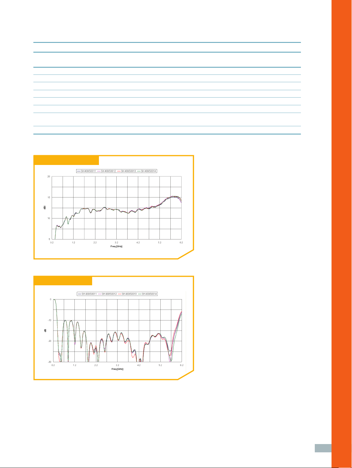
Boresight gain vs frequency
Return loss vs frequency
Measured performance of 4 SH 400 horns: the excellent performance repeatability is proven by the agreeing
plots.
> Measurement antennas
11
Page 3

Mechanical characteristics
Part number SH 68 SH 200 SH 400 SH 600 SH 800 SH 2000 SH 4000
Dimensions 2982.8 1068 540 355.9 270 105 51.6
(H x W X L) x 1615.6 x 585 x 292.3 x 198.7 x 146.2 x 61 x 34
x 2505 mm x 870 mm x 435 mm x 294.6 mm x 225 mm x 104.3 mm x 104.3 mm
Weight (approx) 180 kg 25 kg 4.1 kg 1.8 Kg 1.2 kg 0.5 kg 0.2 kg
Connector N Female
(1)
N Female
(N
Material Aluminum
Treatment Alodine 1200
Aluminum
(3)
Alodine 1200
(1)
N Female
Aluminum
(3)
Alodine 1200
(1)
H+S PC H+S PC H+S PC K Female
3.5 mm Female
(4)
type Female
(2)
3.5 mm 3.5 mm
(2)
Female
(2)
optional)
(3)
Aluminum
Alodine 1200
(3)
Aluminum
Alodine 1200
Aluminum
(3)
Alodine 1200
(3)
Aluminum
Alodine 1200
Color Blue Blue Blue Blue Blue Blue Blue
(1) SPINNER ref. # BN058739 and BN133670
(2) Type 23 PC35-50-0-51/199 UE
(3) Equivalent to MIL-C 5541E class 3
(4) SWMI type 312-14 SF
Wideband horn
SMART POSITIONING
The circular interface allows the user
“W”
“H”
to position and center the antenna
with very high accuracy. The horn
is fastened to the customer’s
mounting support by four screws
“L”
and the alignment is determined
by a precision pin in the mechanical
interface plate.
(3)
SH 68 interface
16 holes
ø12.2
ø670
ø700
SH 200 interface
10
30
ø40±0.015
ø222.0
80
0
-0.05
ø197
ø6 H7
°
24
337
ø8.2
12
Page 4

SH 400 interface
SH 2000 interface
ø110
87 RIF
82 RIF
SH 600 and 800 interface
ø110
M5
ø65
M5
71
ø4 H7
ø4 H7
ø50
ø50
M4
M4
ø3 H7
ø35.4
ø3 H7
ø35.4
10
ø60±0.02ø60±0.02
SH 4000 interface
10
13
> Measurement antennas
Page 5

High precision offset parabolic refl ector for wideband high gain antenna measurements
Mechanical drawing
“W”
“D”
“B”
“A”
Electrical characteristics
Part number SR 40-A (SH 2000 feeder) SR 40-A (SH 4000 feeder)
Polarization Dual Linear Dual Linear
Frequency band [GHz] 2-32 4-40
Return Loss < -7.5 dB, VSWR < 2.5 < -7.5 dB, VSWR < 2.5
XPD on axis > 35 dB > 35 dB
Polarization orientation < 1° on entire frequency band < 1° on entire frequency band
Gain performance > 14 dBi at 2 GHz >17 dBi at 4 GHz
> 28 dBi at 8 GHz >27 dBi at 9 GHz
> 32 dBi at 17 GHz >35 dBi at 20 GHz
> 35 dBi at 26 GHz >37 dBi at 30 GHz
> 34 dBi at 32 GHz >38 dBi at 40 GHz
“L”
“L1”
14
Mechanical characteristics
Part number SR 40-A (SH 2000 feeder) SR 40-A (SH 4000 feeder)
Refl ector shape
Refl ector dimensions D = 400 mm, F/D = 0.5, D = 400 mm, F/D = 0.5,
clearance = 50 mm clearance = 50 mm
Horn antenna 2-32 GHz dual ridge horn 4-40 GHz dual ridge horn
Dimensions (W x A x L) 400 x 315 x 561 mm 400 x 315 x 561 mm
Weight 3.9 kg 3.6 kg
Connectors PC 3.5 Female
Material Aluminum Aluminum
Treatment Alodine 1200
Color Blue Blue
(1) Huber+ Suhner type 23 PC35-50-0-51/199UE
(2) Equivalent to MIC-C 5541E class 3
Super elliptical rim Super elliptical rim
(1)
K Female
(2)
Alodine 1200
(2)
 Loading...