

Page 1
TScan
Page 2

I TScan
TScan is a fast and ultra-accurate planar near-field scanner with the latest motor drive and
encoder technologies. High acceleration of the linear motors for stepped and continuous mode
operation optimizes the performance and cost of the scanner. Excellent manufacturing precision
combined with direct readout high resolution linear encoders and careful alignment ensure
unrivaled mechanical positioning accuracy and planarity. The positioning accuracy for all axes
can then be further improved using MV-Cor™*.
+
Latest motor drive and encoder
technologies
SOLUTION FOR
• Phased Array Antenna Testing
• High Gain Antenna Testing
• Near-field Focused Antenna Testing
• Array Illumination Assessment
• Array Element Failure Analysis
Main features
Technology
• Near-field/Planar
• Optional:
- Near-field/Spherical
- Near-field/Cylindrical
Measurement capabilities
• Gain • Directivity
• Beamwidth • Cross-polar discrimination
• Sidelobe levels • 3D radiation (limited coverage)
• Radiation pattern in • Antenna efficiency
any polarizations- (linear) • Beam pointing properties
• Multi beam antenna
measurement and
calibration
Frequency bands
• 100 MHz to 110 GHz
System configurations
Software
Measurement control, data acquisition and post processing
■ MiDAS
■ 959 Spectrum (North America only)**
Advanced post processing
■ MV-Echo
Insight
Equipment
■ Z-roll probe mount
■ RF absorbers for scanner****
■ AL-4164 positioner controller**
■ Instrumentation rack
■ Uninterruptible power supply
Planar scanner with optional linear motor drive system and
optional direct encoder
Rotary joint for roll axis**
RF cables**
DUT positioner
System for DUT transportation into chamber
RF Tx head
RF Rx head
Port switch
Switch controller
Active antenna beam control
RF system upconverters/downconverters above 20 GHz
Vector network analyzer
Add-ons
DUT stand
Shielded anechoic chamber****
DUT positioner axes for upgrade to cylindrical or spherical NF**
Cylindrical and spherical software transform**
Portable absorber walls****
StarLine linear probe array
Y axis inclination mechanism
Max. weight of DUT
DUT is stationary, therefore the maximum weight of the DUT
is limited by the foundation, antenna mount including any
DUT alignment features, and building infrastructure.
Typical dynamic range
• 80 dB, depending on the frequency and antenna gain
Available movements
• X – travel: up to 50 m • Z – travel: up to 3 m
• Y – travel: up to 26 m • Polarization: 360°
Note:
• To include cylindrical and spherical near-field measurement capabilities in
a planar facility, one can choose to install the DUT on an azimuth positioner
(cylindrical) or a roll-over-azimuth positioner (cylindrical and spherical).
• Longer travel ranges are available based on special order.
Accessories
■ Data acquisition and analysis workstation
High speed channel switching (OFR9800)**
Reference antennas: wideband horns, standard gain horns etc***
Near-field OEWG***
Near-field broadband dual polarized probes with interchangeable
aperture***
Real time controller**
Services
■ Installation
■ Training
■ Warranty
Included Optional Required
* See MV-Cor brochure for more information
** See the ORBIT/FR product catalogs for more information
*** See the MVG antenna catalog for more information
**** See MVG-EMC Systems catalogs for more information
*****See Orbit/FR service brochure for more information
MV-CorTM correction table service*
Post-warranty service plans*****
Periodic alignment
113
2
Page 3

5
System overview
Data Acquisition
& Processing Platform
Real Time
Controller
RT*
I TScan
CHAMBERINSTRUMENTATION ROOM
3
1
4
2
LAN
and RT
PNA
Real time
commands
Rx
Tx
Positioner
Controller
* RT synchronization of measurement subsystems
RF System
Measurements can be performed in both continuous wave
and pulsed mode. In the case of phased array antenna
measurement, the system utilizes the real time controllers
Control
to control and synchronize the measurement system with
the device under test.
114
3
Page 4

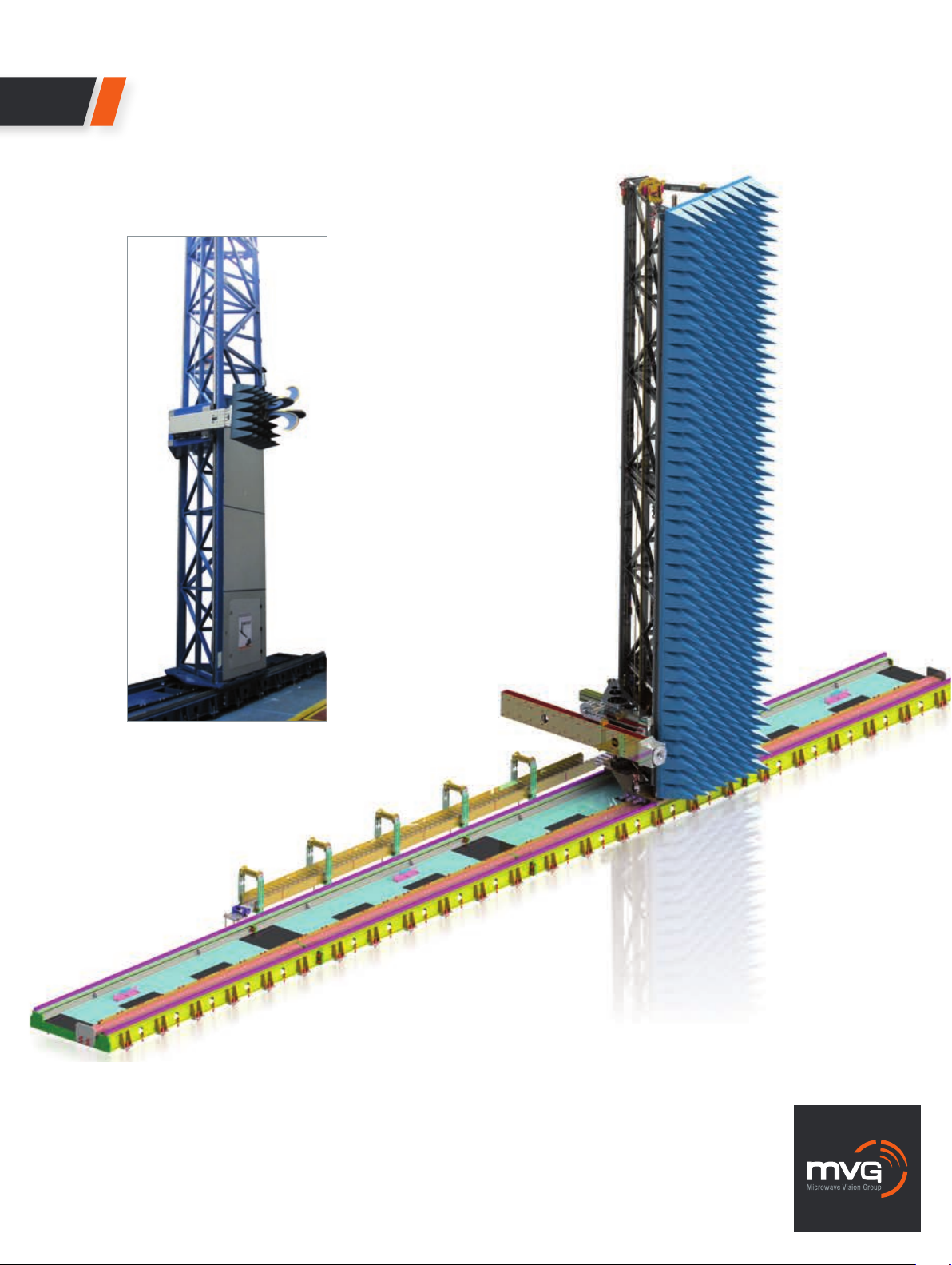
Standard system components
Planar
scanner
The scanner, AL-495XX series
is composed of an X axis linear
slide and a moving tower for the
Y axis. The slide is constructed
of modular sections.
These modules are fixed to
the scanner foundation and
levelled as one integral track.
• T – shape rail with an encoder
system
• Linear motors (optional)
• High linear motor power
• No backlash
Measurement
probes
I TScan
• Open-ended waveguides or
Dual-polarized open-ended
waveguides
MVG antenna catalog
Absorbers
and anechoic
chambers
• A selection of standard,
adapted and specialty
absorbers
• Anechoic chambers with
integrated design, production,
installation and testing services
AEMI absorber catalog
DUT positioning
equipment
• A complete range of rotary
positioners and model towers
are available with air cushion
(optional)
ORBIT/FR positioning
equipment catalog
High speed linear motors
The encoder system with a line of magnetic encoding strip
readers
115
43
Page 5

Mechanical characteristics*
SYSTEMS ULTRA LIGHT LIGHT MEDIUM MEDIUM LARGE EXTRA LARGE
SERIES SERIES SERIES SERIES SERIES SERIES
AL-4951 AL-49510 AL-4952 (R500) AL-49520 (T900) AL-49530 AL-49540
Structure Aluminum Steel Steel Steel Steel Steel
Planarity (RMS) 0.1 mm 0.024 mm 0.015 mm 0.048 mm 0.048 mm 0.048 mm
(up to 4x2.5 m) (up to 15x8 m) (up to 15x12 m) (up to 30x13 m) (up to 30x13 m)
0.048 mm 0.03 mm 0.096 mm 0.15 mm 0.19 mm
(up to 10x7 m) (up to 50x8 m) (up to 50x12 m) (up to 50x18 m) (up to 50x26 m)
Scan Travel X Up to 8 m Up to 10 m Up to 20 m Up to 50 m Up to 50 m Up to 50 m
Scan Travel Y Up to 7 m Up to 7 m Up to 8 m Up to 12 m Up to 18 m Up to 26 m
X Axis Velocity 250 mm/sec 250 - 1000 mm/sec up to 250 mm/sec 250 - 500 mm/sec 250 - 500 mm/sec 125 - 350 mm/sec
Y Axis Velocity 350 mm/sec 250 - 1000 mm/sec up to 250 mm/sec 250 - 1000 mm/sec 250 - 1000 mm/sec 250 - 1000 mm/sec
* Z Roll is available for all above with various travel
116
Product specications and descriptions in this datasheet are subject to change without notice.
Actual products may differ in appearance from images shown.
Copyright MVG 2014
5
 Loading...