

Page 1
T- DualScan
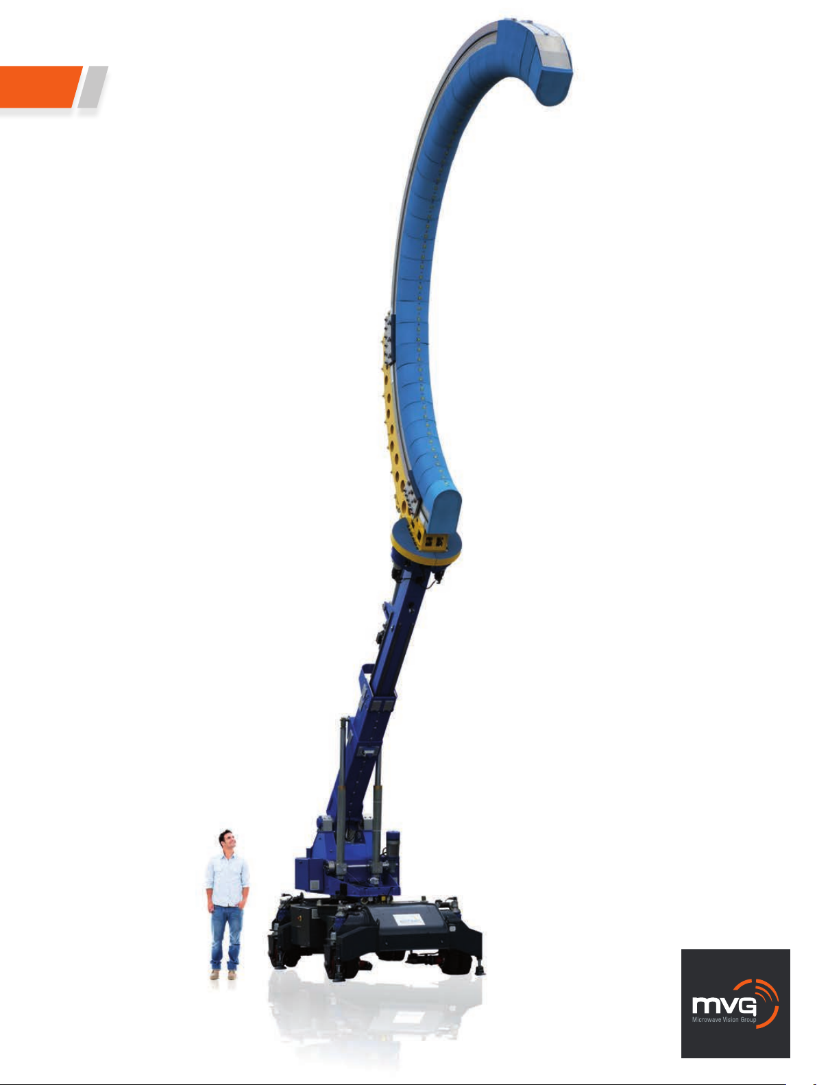
StarBot 4300
Page 2

I StarBot 4300
Similar to the StarBot 4200, the StarBot 4300 is a portable test system designed for antenna
testing of aircrafts or vehicles in-situ. Improving upon its predecessor, in addition to the high
measurement flexibility for radar testing in the nose of an aircraft, its full robotic system and 6
positioning axes enable it to measure antennas anywhere on an aircraft (or vehicle): top, bottom,
nose, tail, wings, etc. The StarBot 4300 is designed to characterize antennas without displacing
the device under test and without enclosure in an anechoic chamber. It is the ideal spherical
near-field antenna test system for extra large devices.
+
• High measurement flexibility
• In-situ measurements of extra large
devices
SOLUTION FOR
• Aircraft/ Vehicle Antenna Characterization
Main features
Technology
• Near-field / Spherical
Measurement capabilities
• On-board antenna testing in its operational environment
• Multi-beam, multi-port, multi-frequency dual polarized
complex measurements
• CW or pulsed measurements for radar testing
• Indoor/Outdoor measurements
• Gain
• Directivity
• Beamwidth
• Cross polar discrimination
• Sidelobe levels
• 3D radiation pattern in any polarization (linear or circular)
• Antenna efficiency
• Beam pointing properties
Frequency bands
• 500 MHz - 18 GHz
Probe array diameter
• 6 m
Typical dynamic range
• 0.5 - 6.0 GHz: 50 dB
• 0.6 - 18 GHz: 45 dB
Available movements
• Robotized trolley and 6 positioning axes
System configurations
Software
Measurement control, data acquisition and post processing
■ SatEnv
MiDAS**
959 Spectrum (North America only)
Near-field/far-field transform
■ SatMap
Advanced post processing
SatSIM
Insight
Equipment
■ Amplification unit
■ Mixer unit
■ N-PAC
■ Primary synthesizer
■ Auxiliary synthesizer
■ Transfer switching unit
■ Power and control unit
■ Probe array power supply
■ Heavy DUT positioner
■ Elevation positioner for
gantry arm
Add-ons
■ Removable mechanical interface supporting laser pointer
and laser telemeter
■ Hardware limit, limit switches and contact detectors for security
■ Flashing light and siren
Shielded anechoic chamber*
Reference antennas (horns, sleeve dipoles, loops)
Accessories
■ PC
■ Instrumentation rack
Services
■ Installation and calibration
■ Training
■ Project management
■ Warranty
Post warranty service plans
■ Positioner controller
■ E-Stop unit
■ Local control unit
■ Real time controller
■ Control Interface Unit
■ Uninterruptible power
supply
■ Instrumentation rack
■ Ethernet switch
AUT port switch
* See MVG-EMC System catalogs Included Optional Required
for more information
** See ORBIT/FR's catalogs for more information
73
2
Page 3

System overview
I StarBot 4300
Data Acquisition
& Processing Platform
Primary
Synthesizer
INSTRUMENTATION ROOM CHAMBER
Real Time
Controller
Triggers
N-PAC
Mixer Unit
USB
Triggers
GPIB
Amplication
Unit
2
1
Transfer
Switching Unit
3
RF
Switch
Auxiliary
Synthesizer
Positioner
Controller
StarBot 4300 is composed of a mechanical scanner paired
with our patented MV-ScanTM probe array of 126 dual polarized probes. The probes are distributed over half an arch
of 6m in diameter. The 6 axes enable flexible positioning so
as to access antennas placed anywhere on an aircraft. The
system is driven by a full remote control robotic system to
facilitate displacements and positioning.
Rx
Tx
One spherical dimension is measured by an electronic
scanning of the probes at a very high speed. The other
dimension is obtained by a simple rotation of the arch
around the first to last probe axis. The goniometric axis
allows for oversampling. The aircraft itself is the only limitation to completing the 360°. Measurements can be performed in CW or pulsed mode thanks to a network analyser.
74
3
Page 4

Standard system components
Arch
• Different arch sizes available
• A choice of probes available
according to the frequency
range
I StarBot 4300
System specifications
Measurement time for 20 frequencies* < 5 min
Typical dynamic range 45 - 50 dB
10 dBi AUT 20 dBi AUT 30 dBi AUT
Positioner
• An innovative 6 axis portable
robot offering versatile
positioning of a probe array
ORBIT/FR positioning
equipment catalog
Absorbers
and anechoic
chambers
• A selection of standard,
adapted and specialty
absorbers
• Anechoic chambers or outdoor
radomes with integrated
design, production, installation
and testing services
AEMI absorber catalog
Antennas
• A choice of reference
antennas (horns, dipoles
and loops) and a single
probe positioner.
MVG antenna catalog
PEAK GAIN ACCURACY (dB)
0.07 - 0.3 GHz - - -
0.3 - 0.4 GHz - - -
0.5 - 0.8 GHz ± 1.2 dB ± 1.0 dB ± 0.7 dB
0.8 - 1.0 GHz ± 0.8 dB ± 0.7 dB ± 0.7 dB
1.0 - 6.0 GHz ± 0.8 dB ± 0.7 dB ± 0.7 dB
6.0 - 18.0 GHz ± 1.1 dB ± 0.9 dB ± 0.8 dB
PEAK GAIN REPEATABILITY (dB)
-10 dB sidelobes accuracy (dB)
0.5 - 0.8 GHz ± 1.5 dB ± 0.9 dB ± 0.6 dB
0.8 - 1.0 GHz ± 1.3 dB ± 0.8 dB ± 0.6 dB
1.0 - 6.0 GHz ± 1.2 dB ± 0.8 dB ± 0.6 dB
6.0 - 16.0 GHz ± 1.5 dB ± 1.1 dB ± 0.9 dB
16.0 - 18.0 GHz ± 1.5 dB ± 1.1 dB ± 0.9 dB
-20 dB sidelobes accuracy (dB)
0.5 - 0.8 GHz - ± 1.5 dB ± 0.8 dB
0.8 - 1.0 GHz - ± 1.3 dB ± 0.8 dB
1.0 - 6.0 GHz - ± 1.2 dB ± 0.8 dB
6.0 - 16.0 GHz - ± 2.2 dB ± 1.8 dB
16.0 - 18.0 GHz - ± 2.2 dB ± 1.8 dB
* • Hemispherical measurement surface (over 180° in Azimuth - typical for
antenna measurement around an aircraft)
• No oversampling
• CW mode: acquisition is asynchronous of RF signal. For pulsed mode
with acquisition synchronous of RF pulse signal, the measurement time
will be linked to the duty cycle of RF pulse signal
A single probe positioner
Mechanical characteristics &
RF equipment characteristics
Angular coverage 182.95°
Probe array diameter 6 m
Frequency range 500 MHz - 18 GHz
Measurement capability CW, pulsed mode
Available movement 6 axis portable robot
(see figure on next page).
ANGLE BETWEEN PROBES
500 MHz - 6 GHz 2.95°
6 GHz - 18 GHz 2.95°
Photo courtesy of Alenia Aeronautica
NUMBER OF PROBES
500 MHz - 6 GHz 63 + 1 ref. channel
6 GHz - 18 GHz 63 + 1 ref. channel
75
43
Page 5

I StarBot 4300
StarBot 4300: a robot scanner offering high measurement flexibility
Motorized wheels - direction and rotation
Azimuth Rotation
Arm Elevation
Arm Extension
Angular correction of vertical axis
Spherical rotation of the arch
Goniometric axis rotation
Stabilization
76
5
Page 6

The overall system is composed of:
The base trolley
The base trolley moves the scanner to the measurement
area. It is mounted on four independent, directional wheels
(A, B, C, D). Once in position, four jacks (K) lock the trolley
to the ground.
The telescopic arm
The telescopic arm holds the spherical probe array and
provides four independent movements. An azimuth table
(E) ensures the rotation of the upper part of the trolley. An
arm (G) lifts the probe array which can be elevated with
an electrical actuator. Finally, a tilt axis positions the probe
array in place.
I StarBot 4300
The measurement scanner
The measurement scanner is composed of a sturdy arch
mounted on a sliding structure (J) that allows the positioning of the probe array. A rotation axis (I) rotates the array
720° so that a partial sphere surrounding the antenna
under test can be measured.
3D radiation pattern of a radar
StarBot 4300 with the arch in vertical position
Product specications and descriptions in this datasheet are subject to change without notice.
Copyright MVG 2014
Actual products may differ in appearance from images shown.
77
65
 Loading...