

ORBITEC OSK 53 G, OSK 38 C, OSK 38 CW, OSK 21 C, OSK 53 GW Operating Instructions Manual
...
Operating instructions for OSK series S / G
As of 13.06.2016
Subject to change
ORBITEC GmbH
Willi-Brehm-Straße 8
D-63500 Seligenstadt
Phone: +49 (0)6182 / 78693-0
Fax: +49 (0)6182 / 78693-10
E-Mail: info@orbitec-group.com
Internet: www.orbitec-group.com
OSK S-series
OSK G-series
1

Operating instructions for OSK series S / G
Table of Contents
1. Preface ........................................................................................................................... 3
2. Safety instructions .......................................................................................................... 4
3. Product overview ............................................................................................................ 5
4. Features/benefits............................................................................................................ 7
5. Measurement chart and scope ....................................................................................... 8
6. Connection to the inverter / control ................................................................................10
7. Instructions ....................................................................................................................11
7.1. assembly of the collets ...........................................................................................11
7.2. Assembly welding head / drive unit ........................................................................13
7.3. Positioning of the electrode ....................................................................................15
7.4. Guidelines for electrode lengths in OSK .................................................................17
7.5. Preparation of pipes ...............................................................................................18
7.6. Tacking of the pipes ...............................................................................................18
7.7. Welding process .....................................................................................................20
8. Maintenance and product care ......................................................................................21
8.1. General instructions ...............................................................................................21
8.2. Cleaning .................................................................................................................22
8.3. Setting the end switch cam .....................................................................................25
8.4. Exchange of the drive shaft ....................................................................................27
8.5. Exchange of graphite nodule ..................................................................................29
8.6. Setting of tension lock ............................................................................................31
9. Type plate key ...............................................................................................................32
10. Accessories (available separately) .............................................................................33
11. Legal notices .............................................................................................................34
12. EC – Declaration of Conformity ..................................................................................35
13. Notes .........................................................................................................................36
2
Operating instructions for OSK series S / G
1. Preface
Thank you for choosing a closed welding head of the OSK series by Orbitec GmbH.
These operating instructions are intended assist in the handling of the OSK.
Please read the operating instructions carefully and completely and keep them for future
reference to avoid misuse.
Orbitec GmbH does not assume any liability for any unauthorised modifications, incorrect
use and repairs, and /or prohibited conversions, which are not expressly authorised by
Orbitec.
The OSK enables the orbital welding of pipes, pipe bends, t-sections etc.
By its closed construction and the interior protective atmosphere, the welding process is
protected from external influences.
The automated welding process facilitates repeatable results and guarantees consistent high
quality.
Furthermore, the welding heads can be changed, therefore welding heads of different sizes
can be used with one single drive unit.
Water cooling is possible for continuous operation and heavy duty applications such as, for
example, high wall thickness.
These operating instructions apply to the G-series, the subsequent S-series, as well as the
compact and water-cooled variants GW, SW, C, CS and CW.
Should you have any question regarding installation, commissioning or operation, please
contact our customer service on telephone number: +49 (0) 6182/78693-0.
3

Operating instructions for OSK series S / G
General Hazard Warnings!
The same rules as for TIG welding (Tungsten Inert-gas welding, or GTAW - Gas
Tungsten arc welding) apply.
The tool may only be used by trained personnel.
The tool may only be used for its intended purpose.
Orbitec GmbH does not assume any liability for unauthorised / incorrect
modifications, repairs, use and conversions, which are not expressly authorised by
Orbitec.
Please read and follow the operating instructions for this product and all related
system components.
Please observe the accident prevention regulations.
Please observe country-specific provisions.
Check all components for damage.
Do not continue to use a product if it is damaged.
Ensure a safe workplace.
Electrical danger!
An electrical shock can be fatal!
Install and earth welding equipment in accordance with local standards.
Do not touch any live components or electrodes with bare hands or wet protective
equipment.
Persons must isolate themselves from earth and the workpiece.
Do not touch any live parts during welding.
Risk of fire and burns!
Welding beads can lead to fire and burns.
Prior to switching on the machine, ensure that there are no solvents present in the
room air, for example in paint shops.
Do not store any flammable objects or cleaning agents at the workspace.
Dirt can often be flammable.
Wear suitable protective gloves.
Danger from radiation!
Ultraviolet and infrared light can cause burns to eyes and skin.
Protect eyes and body, wear suitable safety helmet with filter insert as well as
protective clothing.
Never look towards the electric arc without protection.
Personnel in close proximity must be protected by protective curtains or walls.
Danger from gases and smoke!
Smoke and gas can endanger your health.
Do not inhale the welding fumes.
Ensure sufficient ventilation.
If necessary, use an extraction system.
Observe the safety rules for welding work in small spaces and closed containers.
Danger of explosion!
Caution when using forming gases or gases containing hydrogen.
There is a danger of deflagration.
Only use gases that are suitable for your uses.
When using gases containing hydrogen, maximum 10% hydrogen.
Observe the provisions of the relevant safety data sheets.
Danger of crushing!
Do not reach into the body aperture when the rotor is running.
Do not reach into the moving machine parts.
2. Safety instructions
4
Operating instructions for OSK series S / G
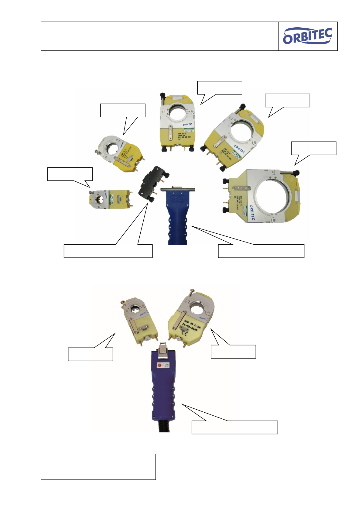
Adapter flange OSK C/G*
Drive unit OSK G
Drive unit OSK C
OSK 115 G
OSK 38 C
OSK 76 G
OSK 53 G
OSK 21 C
OSK 38 C
OSK 21 C
*The adapter flange enables the
connection of a C welding head to a G or S
drive unit
3. Product overview
5
Operating instructions for OSK series S / G
welding head
variant
function
OSK 21
C
gas-cooled
CW
water-cooled
OSK 38
C
gas-cooled
CW
water-cooled
OSK 53
G
gas-cooled
GW
water-cooled
OSK 76
G
gas-cooled
GW
water-cooled
OSK 115
G
gas-cooled
GW
water-cooled
S
gas-cooled
SW
water-cooled
drive unit
compatible with variant:
function
Drive unit OSK C
C
gas-cooled
drive unit OSK CW
CW
water-cooled
drive unit OSK G
G / S
gas-cooled
drive unit OSK GW
GW / SW
water-cooled
drive unit OSK S
G / S
gas-cooled
drive unit OSK SW
GW / SW
water-cooled
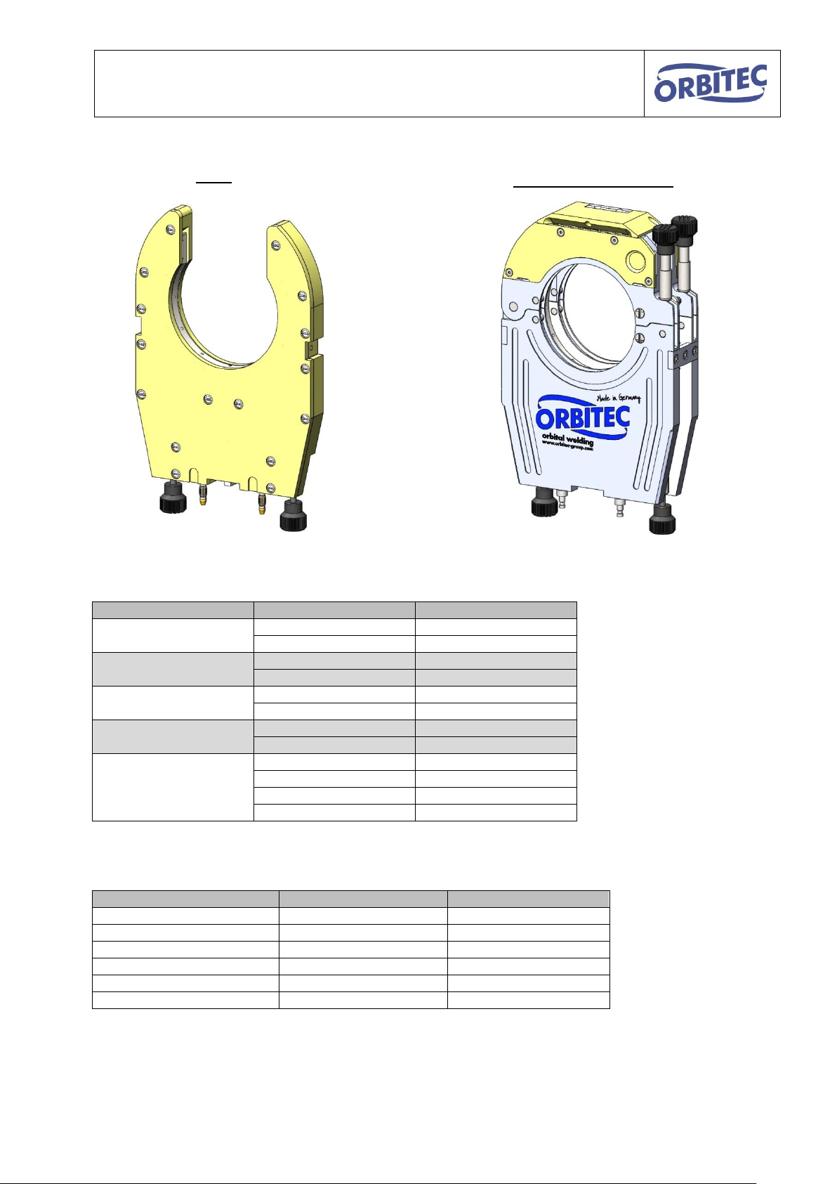
Body
Clamping shell housing
The following OSK welding tools are available:
The following drive units are available:
6

Operating instructions for OSK series S / G
4. Features/benefits
The closed OSK welding heads have the following features:
The closed construction and the inert gas atmosphere inside protect the welding
process against external influences and guarantee a qualitative high-grade welding
seam.
The automated welding process facilitates repeatable results and guarantees
consistent high quality.
The welding head can be separated from the drive unit.
Therefore five different welding heads can be used with one drive unit.
Electrodes with Ø 1.6 mm and Ø 2.4 mm can be used.
Each welding head is available in a water-cooled variant or can be upgraded to a
water-cooled variant (from S-series onwards also OSK 38 and OSK 21).
Collets exchangeable by quick-change system.
Simple assembly and dismantling.
7
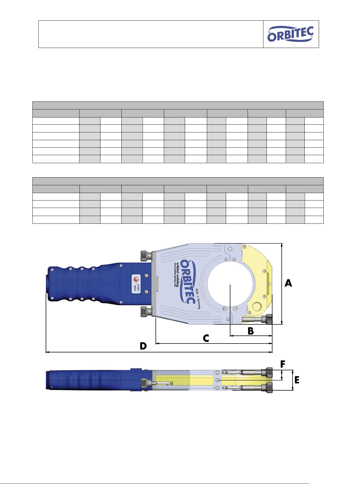
Operating instructions for OSK series S / G
G-series
welding head
A B C D E
F
mm
inch
mm
inch
mm
inch
mm
inch
mm
inch
mm
inch
OSK 21 C
70
2.756
40
1.575
150
5.906
370
14.567
33
1.299
16
.630
OSK 38 C
102
4.016
53
2.087
175
6.890
390
15.354
33
1.299
16
.630
OSK 53 G / GW
140
5.512
73
2.874
210
8.268
430
16.929
44
1.732
22
.866
OSK 76 G / GW
160
6.299
83
3.268
230
9.055
445
17.520
44
1.732
22
.866
OSK 115 G / GW
200
7.874
103
4.055
270
10.630
485
19.094
44
1.732
22
.866
S-series
welding head
A B C D E
F
mm
inch
mm
inch
mm
inch
mm
inch
mm
inch
mm
inch
OSK 21 CW
70
2.756
39.5
1.555
146
5.748
365.5
14.390
35
1.378
17.5
.689
OSK 38 CW
102
4.016
54
2.156
177
6.969
396
15.591
35
1.378
17.5
.689
OSK 115 S / SW
200
7.874
103
4.055
270
10.630
487.5
19.192
40
1.575
20
.787
5. Measurement chart and scope
The dimensions of the OSK series are as follows:
8

Operating instructions for OSK series S / G
welding head
scope (outside diameter)
scope (outside diameter)
OSK 21
3.17 mm – 21.3 mm
0.125 inch – 0.839 inch
OSK 38
3.17 mm – 38.1 mm
0.125 inch – 1.500 Inch
OSK 53
6 mm – 53 mm
0.250 inch – 2.087 Inch
OSK 76
6 mm – 76.2 mm
0.250 inch – 3.000 Inch
OSK 115
8 mm – 114.3 mm
0.368 inch – 4.500 inch
Clamping jaws are
available in all
common pipe
diameters.
(special sizes on
request)
The scopes of the OSK series is as follows:
9
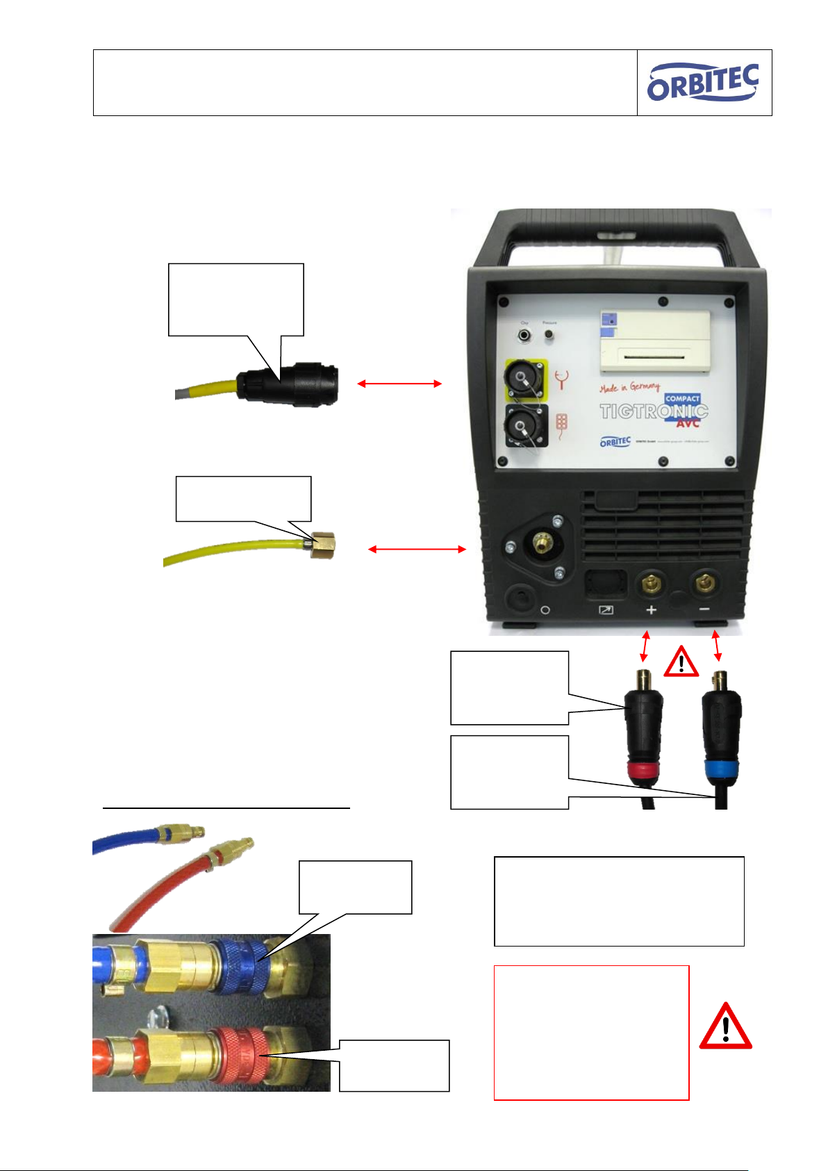
Operating instructions for OSK series S / G
Gas connection
Connection
control
marked yellow
positive pole
(Mass)
marked red
minus pole
(electrode)
marked blue
Additionally in case of water-cooling:
Water flow
blue
Water return
flow red
Please follow the
relevant instructions
regarding the
commissioning, operation
and the safety
precautions
In case of water-cooling, you will
also require the water cooling unit
Cool 50
Item no. 1.2.0118
6. Connection to the inverter / control
10

Operating instructions for OSK series S / G
Rear lock (fixed)
Front lock (flexible)
Collets
Recesses for lock
Lock closed
(for the locking of the
collets)
Lock open
(for the insertion and
removal of the collets)
Recess
inside
Recess
outside
Large recesses to the rear
(fixed lock)
Small recesses to the front
(flexible lock)
7. Instructions
7.1. assembly of the collets
As a rule, one set of collets consisting of four identical individual parts is required. These are
inserted into the clamping shell housing and each are held into place and locked by 2
cylinders.
11

Operating instructions for OSK series S / G
3. Close lock.
1. Insert collet at the rear
2. Insert collet at the front
1.
2.
3.
Open the lock and insert the collets as depicted.
Assemble the remaining three collets in the same way.
12
 Loading...