

ORBITEC OSK 53 G, OSK 38 C, OSK 38 CW, OSK 21 C, OSK 53 GW Operating Instructions Manual [en, de]
...Page 1
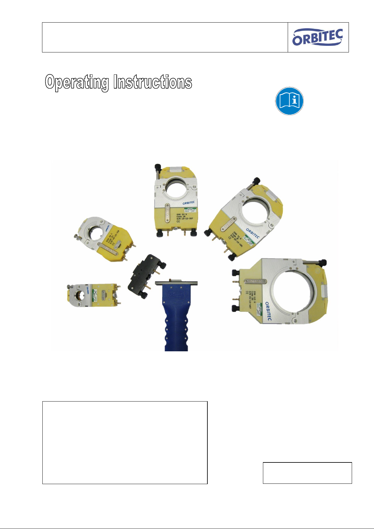
Operating instructions for OSK series S / G
As of 13.06.2016
Subject to change
ORBITEC GmbH
Willi-Brehm-Straße 8
D-63500 Seligenstadt
Phone: +49 (0)6182 / 78693-0
Fax: +49 (0)6182 / 78693-10
E-Mail: [email protected]
Internet: www.orbitec-group.com
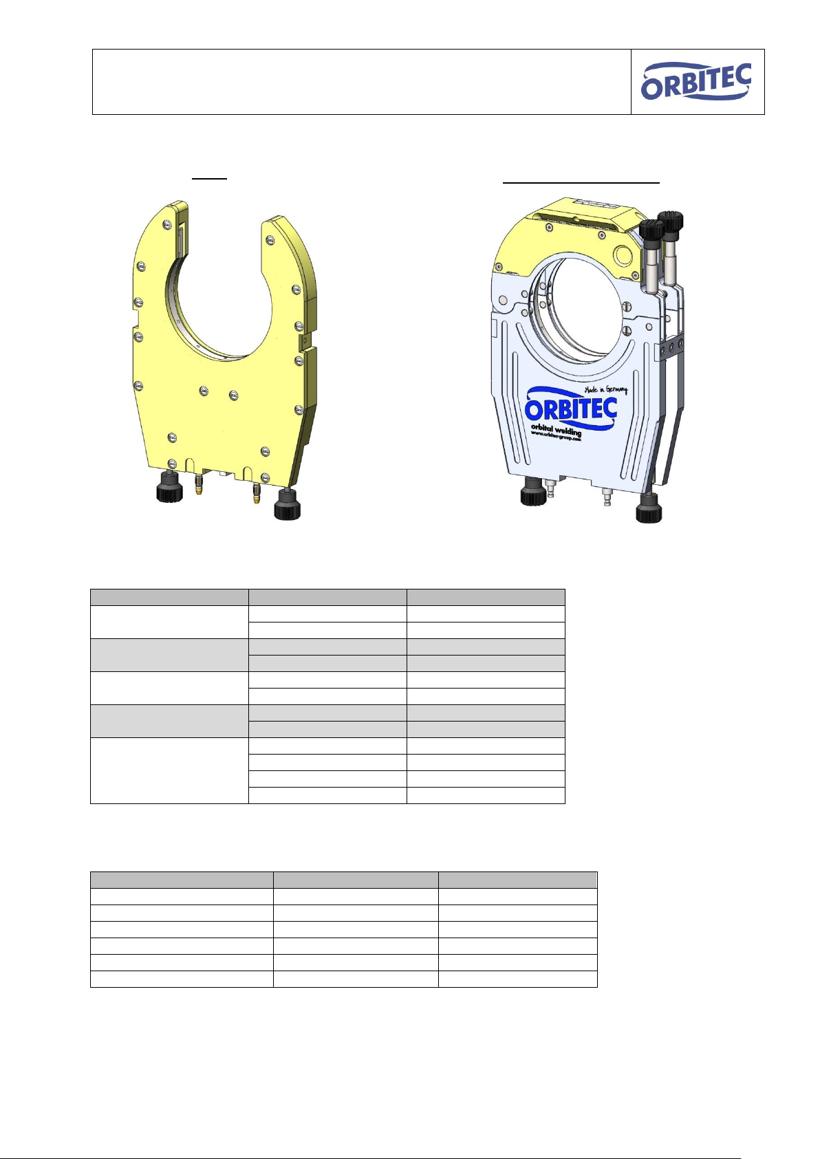
OSK S-series
OSK G-series
1
Page 2

Operating instructions for OSK series S / G
Table of Contents
1. Preface ........................................................................................................................... 3
2. Safety instructions .......................................................................................................... 4
3. Product overview ............................................................................................................ 5
4. Features/benefits............................................................................................................ 7
5. Measurement chart and scope ....................................................................................... 8
6. Connection to the inverter / control ................................................................................10
7. Instructions ....................................................................................................................11
7.1. assembly of the collets ...........................................................................................11
7.2. Assembly welding head / drive unit ........................................................................13
7.3. Positioning of the electrode ....................................................................................15
7.4. Guidelines for electrode lengths in OSK .................................................................17
7.5. Preparation of pipes ...............................................................................................18
7.6. Tacking of the pipes ...............................................................................................18
7.7. Welding process .....................................................................................................20
8. Maintenance and product care ......................................................................................21
8.1. General instructions ...............................................................................................21
8.2. Cleaning .................................................................................................................22
8.3. Setting the end switch cam .....................................................................................25
8.4. Exchange of the drive shaft ....................................................................................27
8.5. Exchange of graphite nodule ..................................................................................29
8.6. Setting of tension lock ............................................................................................31
9. Type plate key ...............................................................................................................32
10. Accessories (available separately) .............................................................................33
11. Legal notices .............................................................................................................34
12. EC – Declaration of Conformity ..................................................................................35
13. Notes .........................................................................................................................36
2
Page 3
Operating instructions for OSK series S / G
1. Preface
Thank you for choosing a closed welding head of the OSK series by Orbitec GmbH.
These operating instructions are intended assist in the handling of the OSK.
Please read the operating instructions carefully and completely and keep them for future
reference to avoid misuse.
Orbitec GmbH does not assume any liability for any unauthorised modifications, incorrect
use and repairs, and /or prohibited conversions, which are not expressly authorised by
Orbitec.
The OSK enables the orbital welding of pipes, pipe bends, t-sections etc.
By its closed construction and the interior protective atmosphere, the welding process is
protected from external influences.
The automated welding process facilitates repeatable results and guarantees consistent high
quality.
Furthermore, the welding heads can be changed, therefore welding heads of different sizes
can be used with one single drive unit.
Water cooling is possible for continuous operation and heavy duty applications such as, for
example, high wall thickness.
These operating instructions apply to the G-series, the subsequent S-series, as well as the
compact and water-cooled variants GW, SW, C, CS and CW.
Should you have any question regarding installation, commissioning or operation, please
contact our customer service on telephone number: +49 (0) 6182/78693-0.
3
Page 4

Operating instructions for OSK series S / G
General Hazard Warnings!
The same rules as for TIG welding (Tungsten Inert-gas welding, or GTAW - Gas
Tungsten arc welding) apply.
The tool may only be used by trained personnel.
The tool may only be used for its intended purpose.
Orbitec GmbH does not assume any liability for unauthorised / incorrect
modifications, repairs, use and conversions, which are not expressly authorised by
Orbitec.
Please read and follow the operating instructions for this product and all related
system components.
Please observe the accident prevention regulations.
Please observe country-specific provisions.
Check all components for damage.
Do not continue to use a product if it is damaged.
Ensure a safe workplace.
Electrical danger!
An electrical shock can be fatal!
Install and earth welding equipment in accordance with local standards.
Do not touch any live components or electrodes with bare hands or wet protective
equipment.
Persons must isolate themselves from earth and the workpiece.
Do not touch any live parts during welding.
Risk of fire and burns!
Welding beads can lead to fire and burns.
Prior to switching on the machine, ensure that there are no solvents present in the
room air, for example in paint shops.
Do not store any flammable objects or cleaning agents at the workspace.
Dirt can often be flammable.
Wear suitable protective gloves.
Danger from radiation!
Ultraviolet and infrared light can cause burns to eyes and skin.
Protect eyes and body, wear suitable safety helmet with filter insert as well as
protective clothing.
Never look towards the electric arc without protection.
Personnel in close proximity must be protected by protective curtains or walls.
Danger from gases and smoke!
Smoke and gas can endanger your health.
Do not inhale the welding fumes.
Ensure sufficient ventilation.
If necessary, use an extraction system.
Observe the safety rules for welding work in small spaces and closed containers.
Danger of explosion!
Caution when using forming gases or gases containing hydrogen.
There is a danger of deflagration.
Only use gases that are suitable for your uses.
When using gases containing hydrogen, maximum 10% hydrogen.
Observe the provisions of the relevant safety data sheets.
Danger of crushing!
Do not reach into the body aperture when the rotor is running.
Do not reach into the moving machine parts.
2. Safety instructions
4
Page 5
Operating instructions for OSK series S / G
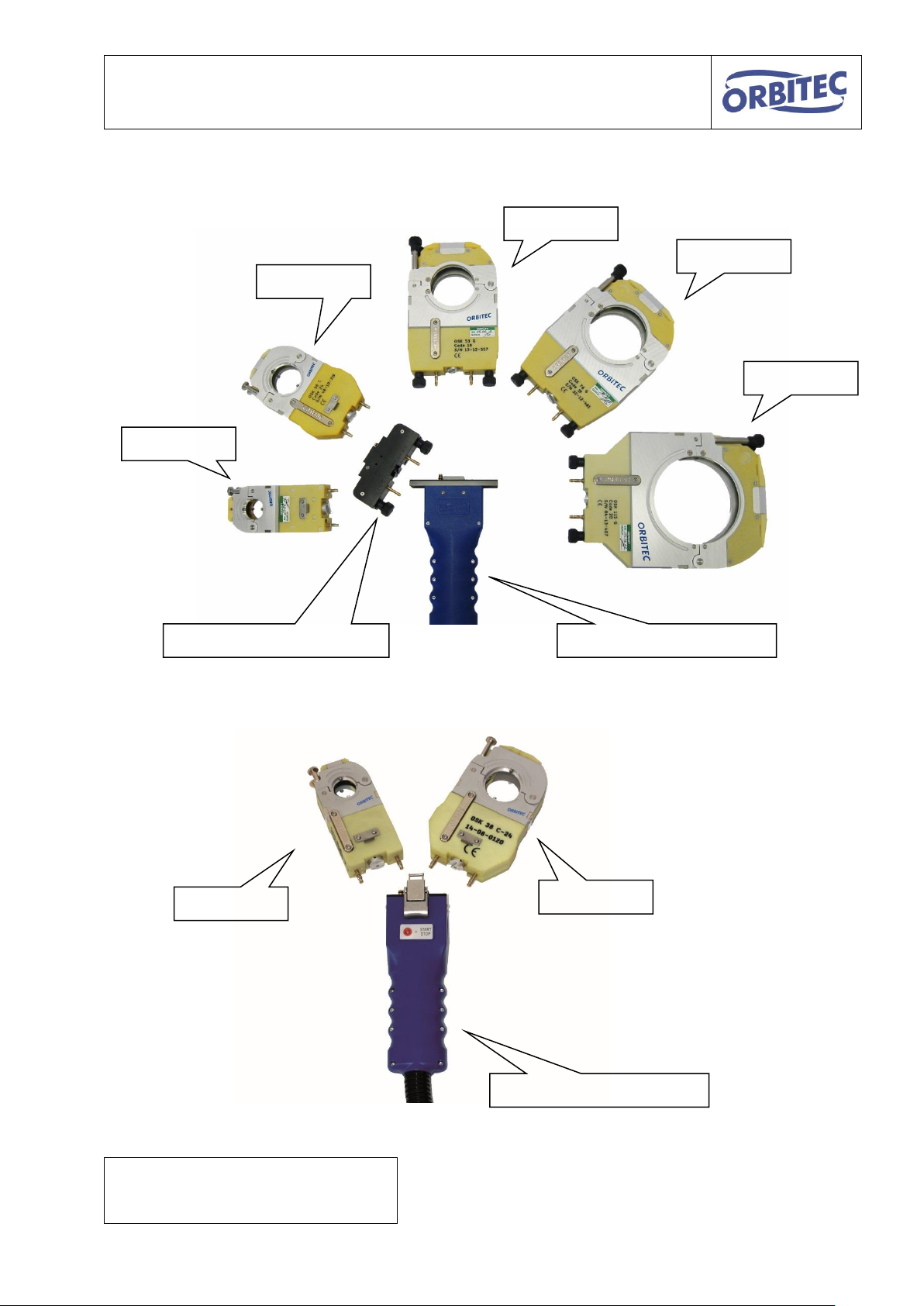
Adapter flange OSK C/G*
Drive unit OSK G
Drive unit OSK C
OSK 115 G
OSK 38 C
OSK 76 G
OSK 53 G
OSK 21 C
OSK 38 C
OSK 21 C
*The adapter flange enables the
connection of a C welding head to a G or S
drive unit
3. Product overview
5
Page 6
Operating instructions for OSK series S / G
welding head
variant
function
OSK 21
C
gas-cooled
CW
water-cooled
OSK 38
C
gas-cooled
CW
water-cooled
OSK 53
G
gas-cooled
GW
water-cooled
OSK 76
G
gas-cooled
GW
water-cooled
OSK 115
G
gas-cooled
GW
water-cooled
S
gas-cooled
SW
water-cooled
drive unit
compatible with variant:
function
Drive unit OSK C
C
gas-cooled
drive unit OSK CW
CW
water-cooled
drive unit OSK G
G / S
gas-cooled
drive unit OSK GW
GW / SW
water-cooled
drive unit OSK S
G / S
gas-cooled
drive unit OSK SW
GW / SW
water-cooled
Body
Clamping shell housing
The following OSK welding tools are available:
The following drive units are available:
6
Page 7

Operating instructions for OSK series S / G
4. Features/benefits
The closed OSK welding heads have the following features:
The closed construction and the inert gas atmosphere inside protect the welding
process against external influences and guarantee a qualitative high-grade welding
seam.
The automated welding process facilitates repeatable results and guarantees
consistent high quality.
The welding head can be separated from the drive unit.
Therefore five different welding heads can be used with one drive unit.
Electrodes with Ø 1.6 mm and Ø 2.4 mm can be used.
Each welding head is available in a water-cooled variant or can be upgraded to a
water-cooled variant (from S-series onwards also OSK 38 and OSK 21).
Collets exchangeable by quick-change system.
Simple assembly and dismantling.
7
Page 8
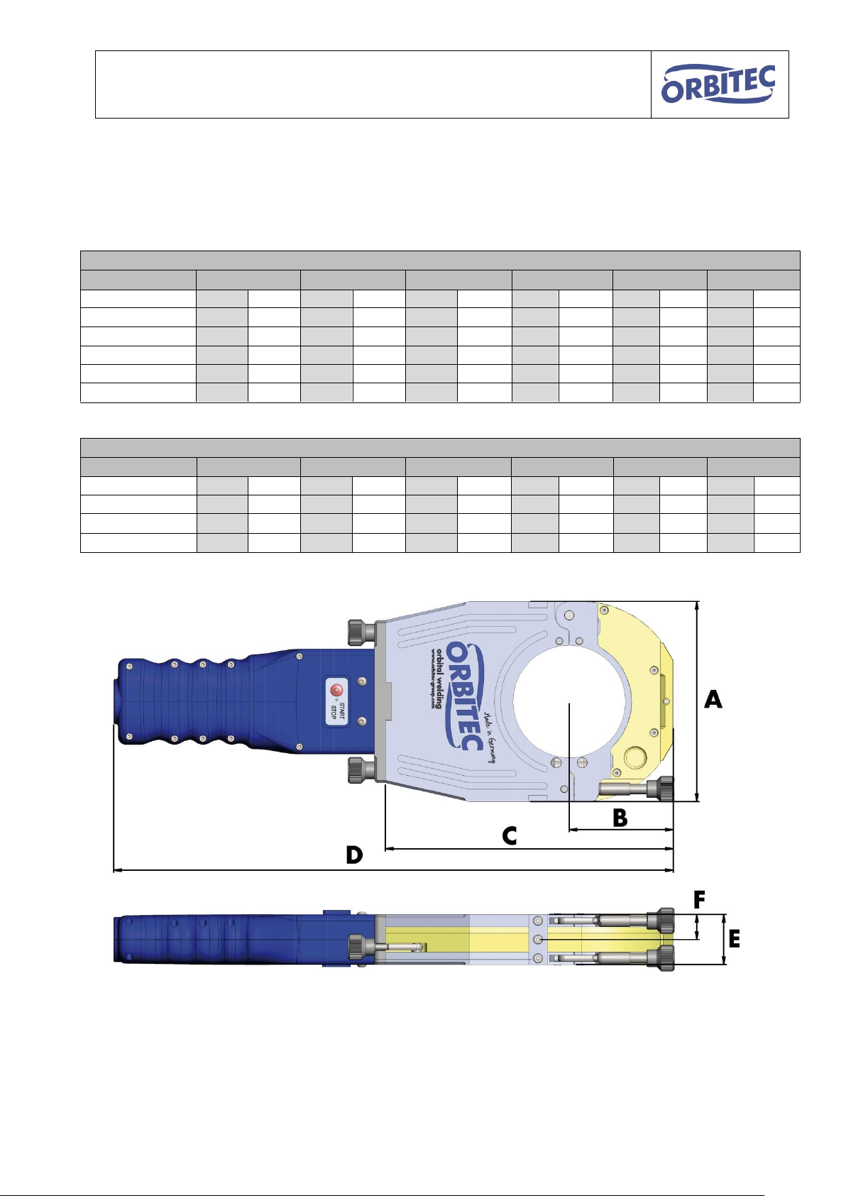
Operating instructions for OSK series S / G
G-series
welding head
A B C D E
F
mm
inch
mm
inch
mm
inch
mm
inch
mm
inch
mm
inch
OSK 21 C
70
2.756
40
1.575
150
5.906
370
14.567
33
1.299
16
.630
OSK 38 C
102
4.016
53
2.087
175
6.890
390
15.354
33
1.299
16
.630
OSK 53 G / GW
140
5.512
73
2.874
210
8.268
430
16.929
44
1.732
22
.866
OSK 76 G / GW
160
6.299
83
3.268
230
9.055
445
17.520
44
1.732
22
.866
OSK 115 G / GW
200
7.874
103
4.055
270
10.630
485
19.094
44
1.732
22
.866
S-series
welding head
A B C D E
F
mm
inch
mm
inch
mm
inch
mm
inch
mm
inch
mm
inch
OSK 21 CW
70
2.756
39.5
1.555
146
5.748
365.5
14.390
35
1.378
17.5
.689
OSK 38 CW
102
4.016
54
2.156
177
6.969
396
15.591
35
1.378
17.5
.689
OSK 115 S / SW
200
7.874
103
4.055
270
10.630
487.5
19.192
40
1.575
20
.787
5. Measurement chart and scope
The dimensions of the OSK series are as follows:
8
Page 9

Operating instructions for OSK series S / G
welding head
scope (outside diameter)
scope (outside diameter)
OSK 21
3.17 mm – 21.3 mm
0.125 inch – 0.839 inch
OSK 38
3.17 mm – 38.1 mm
0.125 inch – 1.500 Inch
OSK 53
6 mm – 53 mm
0.250 inch – 2.087 Inch
OSK 76
6 mm – 76.2 mm
0.250 inch – 3.000 Inch
OSK 115
8 mm – 114.3 mm
0.368 inch – 4.500 inch
Clamping jaws are
available in all
common pipe
diameters.
(special sizes on
request)
The scopes of the OSK series is as follows:
9
Page 10
Operating instructions for OSK series S / G
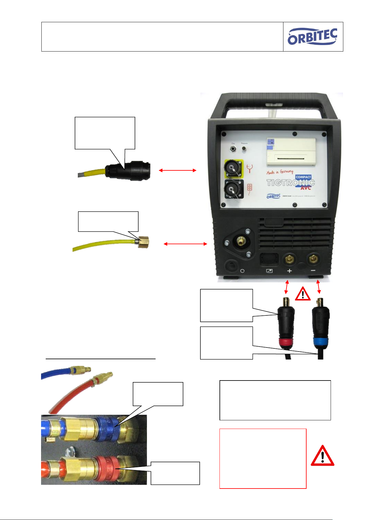
Gas connection
Connection
control
marked yellow
positive pole
(Mass)
marked red
minus pole
(electrode)
marked blue
Additionally in case of water-cooling:
Water flow
blue
Water return
flow red
Please follow the
relevant instructions
regarding the
commissioning, operation
and the safety
precautions
In case of water-cooling, you will
also require the water cooling unit
Cool 50
Item no. 1.2.0118
6. Connection to the inverter / control
10
Page 11

Operating instructions for OSK series S / G
Rear lock (fixed)
Front lock (flexible)
Collets
Recesses for lock
Lock closed
(for the locking of the
collets)
Lock open
(for the insertion and
removal of the collets)
Recess
inside
Recess
outside
Large recesses to the rear
(fixed lock)
Small recesses to the front
(flexible lock)
7. Instructions
7.1. assembly of the collets
As a rule, one set of collets consisting of four identical individual parts is required. These are
inserted into the clamping shell housing and each are held into place and locked by 2
cylinders.
11
Page 12

Operating instructions for OSK series S / G
3. Close lock.
1. Insert collet at the rear
2. Insert collet at the front
1.
2.
3.
Open the lock and insert the collets as depicted.
Assemble the remaining three collets in the same way.
12
Page 13

Operating instructions for OSK series S / G
Coupling
(The coupling must be aligned with
each other during assembly!)
2x power
2x power
3x contacts for limit switch
3x contacts for limit switch
2x water connection with water stop
coupling
(only with water-cooled variant,
these connections are not present
with gas-cooled variant)
Gas
Gas
Attention!
The water-cooled variants OSK 38 CW and
OSK 21 CW as well as their drive unit OSK CW
do not have a water stop coupling.
When disconnecting the welding head from the
drive unit, beware of water leakage
7.2. Assembly welding head / drive unit
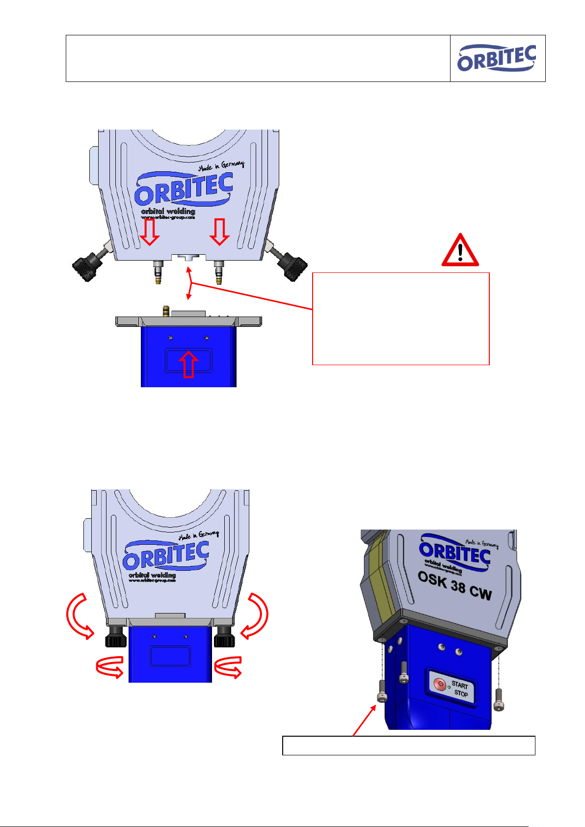
Due to the plug-in principle, different welding heads can be connected to the same drive unit.
Overview of the media:
13
Page 14
Operating instructions for OSK series S / G
Attention!
Ensure that the couplings are
aligned, otherwise the welding
head cannot be completely
assembled.
Do not use force.
There are no knurled-head screws in the
water-cooled variant OSK 38 CW and OSK
21 CW. The connection is made with four
cylinder head screws. The remaining
assembly is identical.
4x cylinder screw hexagon socket ISO 4762 M4x12
Connect the welding head with the drive unit.
Fit in the knurled-head screw
and tighten it by hand.
14
Page 15

Operating instructions for OSK series S / G
For supplementary information on control see operating instructions for:
Tigtronic Basic 2, 3, 4
Tictronic COMPACT 200 MV
Position for Ø1.6
Position for Ø2.4
Never insert two electrodes
simultaneously
The position of the electrodes can be
inverted, depending on design
Open the clamping shell
Proceed with the rotor as per control, until
the desired clamping screw can be
reached.
Attention!
Danger of crushing
7.3. Positioning of the electrode
Electrodes with a diameter of 1.6mm and 2.4mm can be used.
15
Page 16
Operating instructions for OSK series S / G
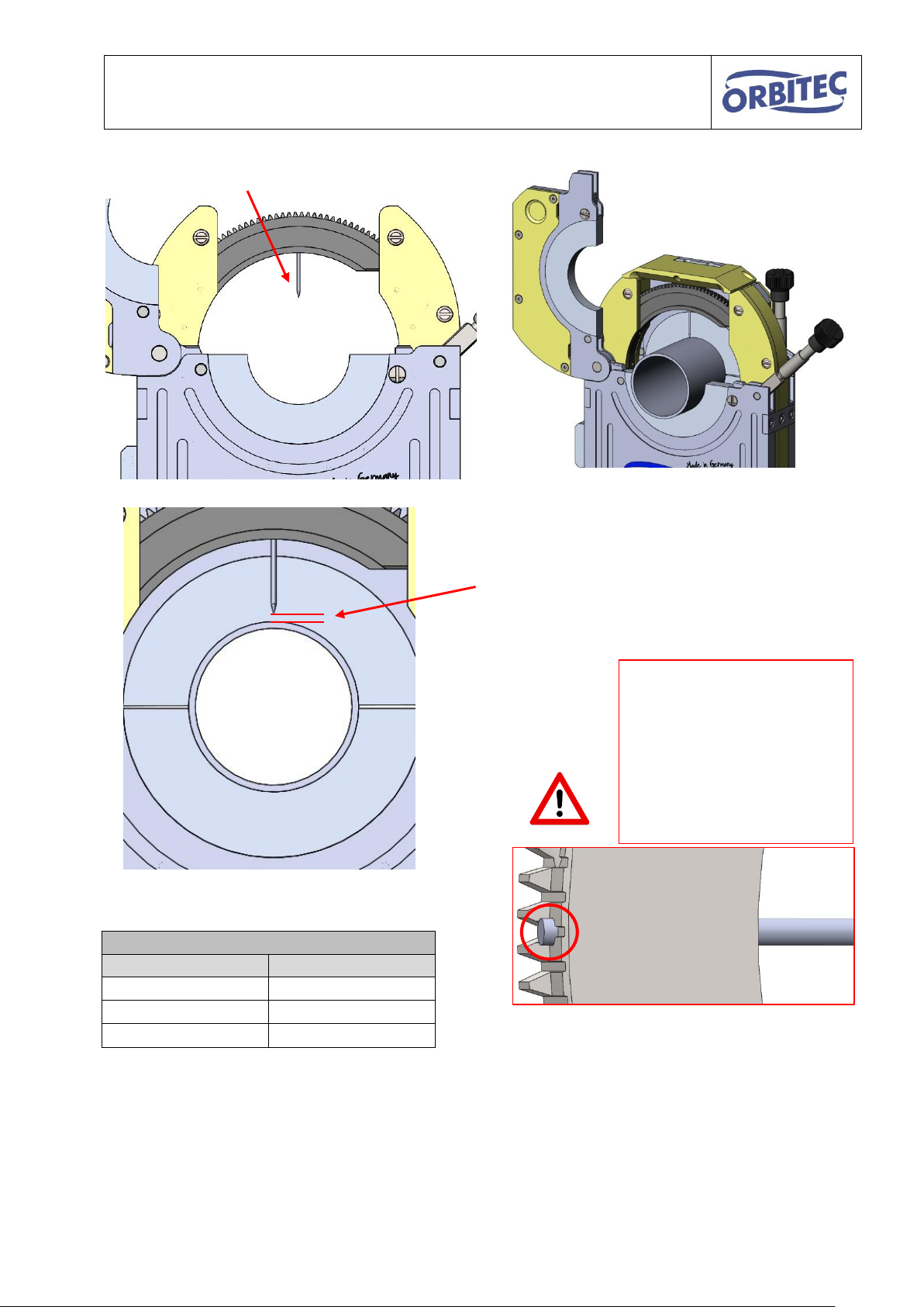
Guidelines for electrode gap
wall thickness
Electrode gap
0.5 mm - 1.0 mm
0.8 mm
1.25 mm - 2.0 mm
1.0 - 1.8 mm
2.25 mm - 3.2 mm
2.0 - 2.6 mm
Fit electrode
fit suitable pipe diameter and
tighten with one side of the
clamping shell housing.
Set the electrode gap with feeler gauge and fix
with the clamping screw.
The gap is dependent on the wall thickness
(see guidelines)
Attention!
The electrode must not
protrude into the gear
wheel area.
This results in damage of
the gear wheels and
potentially the body.
Remove the adjustment pipe again.
16
Page 17
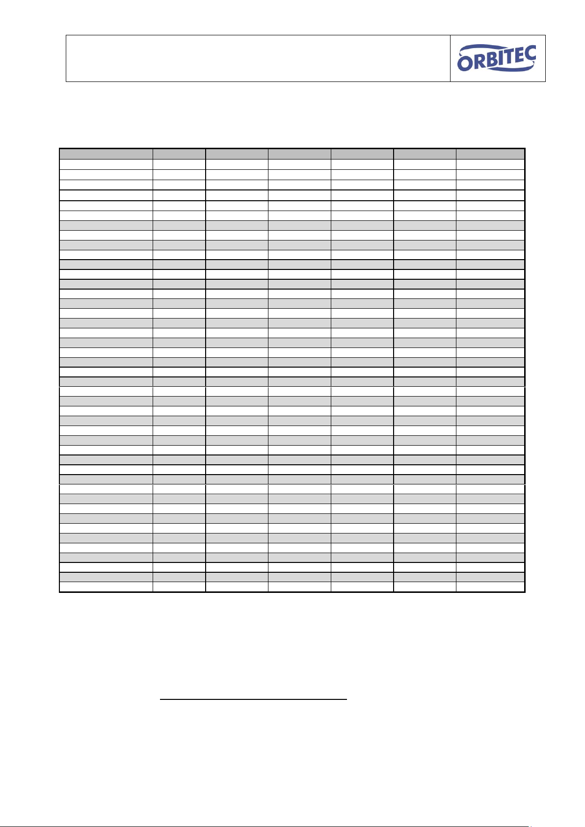
Operating instructions for OSK series S / G
Heads
OSK-13 S
OSK-21 C
OSK-38 C
OSK-53 G
OSK-76 G
OSK-115 G / S
Head number
25
17
24
18
19
20
Rotor outside Ø
D = 32.5
D = 58
D = 86
D = 116
D = 136
D = 176
Gas volume
4-6 L/min
6-8 L/min
10-12 L/min
12-16 L/min
14-18 L/min
14-18 L/min
Electrodes Ø
1.0 / 1.6
1.6 / 2.4
1.6 / 2.4
1.6 / 2.4
1.6 / 2.4
1.6 / 2.4
Pipe OD
3.17 mm
14 mm
26 mm
40 mm 6 mm
12 mm
25 mm
39 mm
54 mm
64 mm 6.35 mm
12 mm
25 mm
39 mm
53 mm
63 mm 8 mm
11 mm
24 mm
38 mm
53 mm
63 mm
83 mm
9.53 mm
10 mm
23 mm
37 mm
52 mm
62 mm
82 mm
10 mm
10 mm
23 mm
37 mm
52 mm
62 mm
82 mm
12 mm
9 mm
22 mm
36 mm
51 mm
61 mm
81 mm
12.7 mm
9 mm
21 mm
35 mm
50 mm
60 mm
80 mm
13 mm
21 mm
35 mm
50 mm
60 mm
80 mm
16 mm
20 mm
34 mm
49 mm
59 mm
79 mm
18 mm
18 mm
32 mm
47 mm
57 mm
77 mm
19 mm
17 mm
31 mm
46 mm
56 mm
76 mm
19.05 mm
17 mm
31 mm
46 mm
56 mm
76 mm
21.3 mm
16 mm
30 mm
45 mm
55 mm
75 mm
23 mm
15 mm
29 mm
44 mm
54 mm
74 mm
25.4 mm
14 mm
28 mm
43 mm
53 mm
73 mm
26.9 mm
27 mm
42 mm
52 mm
72 mm
28 mm
27 mm
42 mm
52 mm
72 mm
29 mm
26 mm
41 mm
51 mm
71 mm
33.7 mm
24 mm
39 mm
49 mm
69 mm
35 mm
23 mm
38 mm
48 mm
68 mm
38.1 mm
22 mm
37 mm
47 mm
67 mm
41 mm
35 mm
45 mm
65 mm
42.4 mm
34 mm
44 mm
64 mm
44.5 mm
33 mm
43 mm
63 mm
48.3 mm
31 mm
41 mm
61 mm
50.8 mm
30 mm
40 mm
60 mm
53 mm
29 mm
39 mm
59 mm
54 mm
39 mm
59 mm
60.3 mm
35 mm
55 mm
63.5 mm
34 mm
54 mm
70 mm
31 mm
51 mm
76.1 mm
28 mm
48 mm
85 mm
43 mm
88.9 mm
41 mm
101.6 mm
35 mm
104 mm
34 mm
108 mm
32 mm
114.3 mm
28 mm
7.4. Guidelines for electrode lengths in OSK
For special sizes, use the following formula:
Electrode length =
17
Page 18

Operating instructions for OSK series S / G
Align the pipes centrally and
gap-free
Manually set 4 spot welds,
each offset by 90°
Recommendation: 1.2.0129 prism DA 5 – 30 mm
1.2.0130 prism DA 10 – 65 mm
1.2.0131 prism DA 20 – 115 mm
7.5. Preparation of pipes
The quality of the welding seam depends on the preparation.
The following must be noted:
Preparation of the pipe:
square cut, good surface quality, cleanliness, burr-free, free from fat and oil
Recommendation: 1.2.4503 tube saw ORS 115
1.3.4101 Planfix 40
1.2.4005 Planfix 115
7.6. Tacking of the pipes
The components must be tacked on prior to the orbital welding.
It is necessary to use forming gas depending on the application.
Manual tacking:
18
Page 19
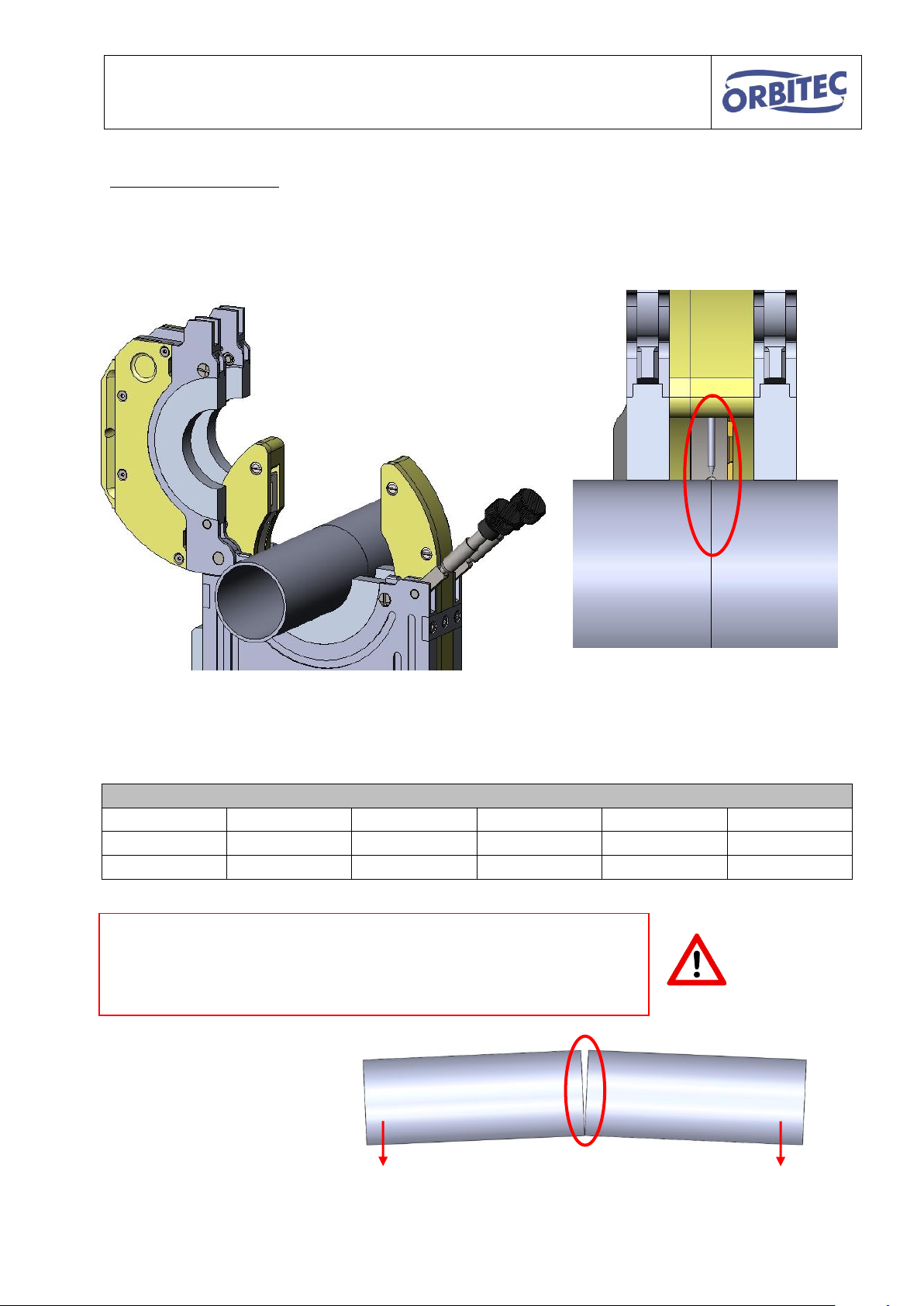
Operating instructions for OSK series S / G
Parameter
Welding head:
OSK 21 C
OSK 38 C
OSK 53 G
OSK 76 G
OSK 115 G / S
Head number
17
24
18
19
20
Gas volume
6-8 L/min
10-12 L/min
12-16 L/min
14-18 L/min
14-18 L/min
Attention!
Only recommended for short pieces of pipe, approximately 50 100mm.
For longer pieces of pipe, the manual tacking is indispensable.
Tacking with the OSK:
It is also possible to tack with the orbital welding head.
Insert the prepared pipes in the welding head, so that the joint with the electrode forms a line.
Close the welding head and start the tacking process.
It is mandatory to use forming gas depending on the application.
19
Page 20

Operating instructions for OSK series S / G
Rotor back in basic position
Completely open the clamping
shell housing
Insert the tacked pipe and align
central to the electrode.
Close clamping shell housing and weld together.
It is mandatory to form depending on the
application.
Attention!
Danger from burns!
The welding head gets hot.
Gloves should be worn.
7.7. Welding process
20
Page 21

Operating instructions for OSK series S / G
8. Maintenance and product care
8.1. General instructions
The tool should only be used for the intended application.
Do not make any modifications to the tool.
Do not expose the product to extreme environmental conditions (f. ex. rain).
Use only accessories of Orbitec GmbH.
Regularly check and, if necessary, replace the electrode.
Blow out the water channels of the water-cooled clamping shell housing with compressed air
prior to putting these down, in order to avoid leaks.
Do not allow the welding head to overheat (maximum 150°C).
21
Page 22
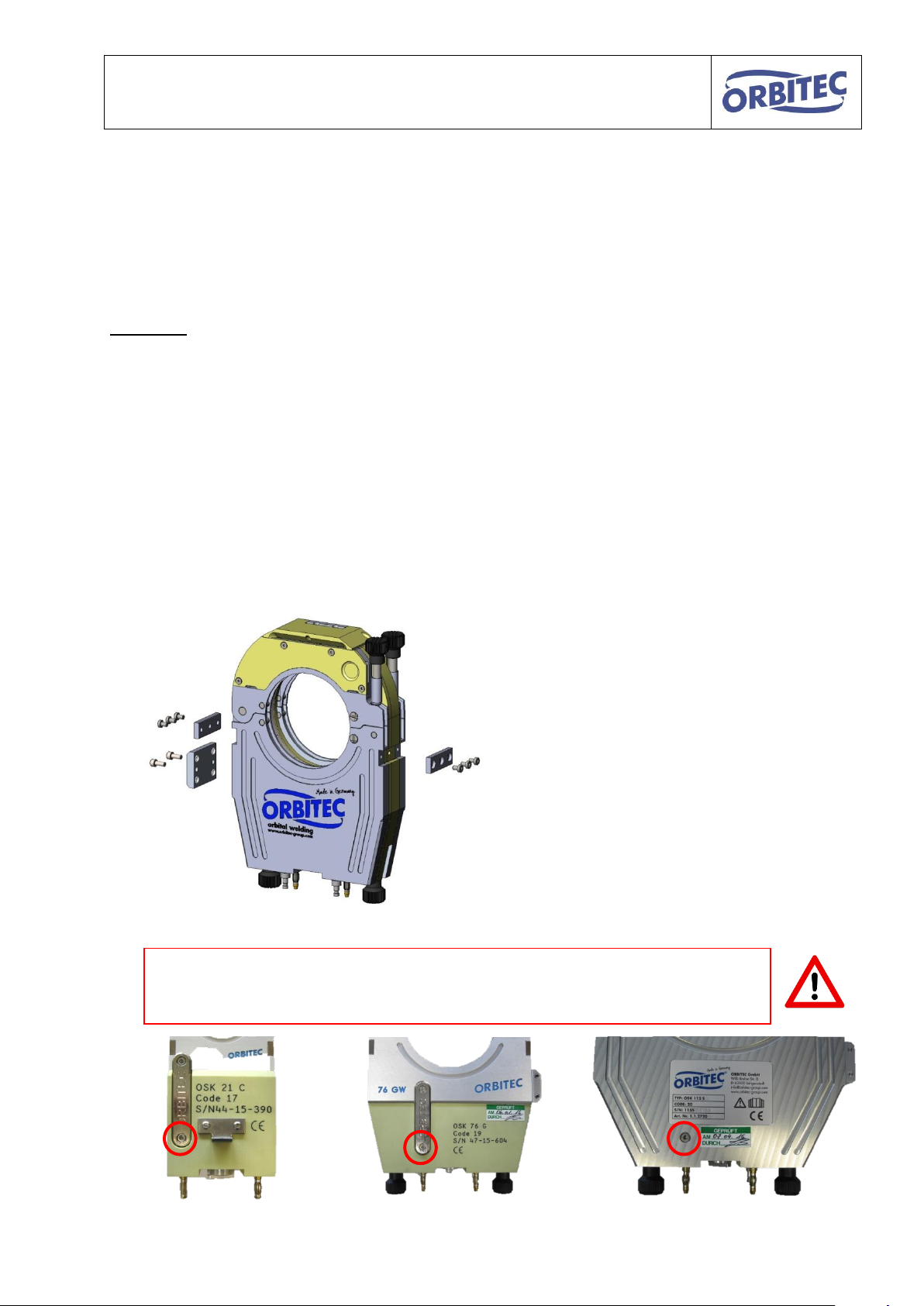
Operating instructions for OSK series S / G
Disassemble both mounting pass rails and,
if present, the water bridge.
(In the G-series the screws on the mounting
pass rails can potentially be different, please
pay attention to the correct positioning at
assembly.)
Remove the screw at the back of the welding head.
This screw ensures the power transmission, ascertain that it is properly fitted
again on assembly. If the screw is missing, this can cause backfires.
8.2. Cleaning
The welding head must be cleaned regularly, to reduce the wear and tear and to increase the
service life. If necessary, this guideline must be adjusted according to use and degree of
contamination.
Guideline:
The welding head must be cleaned at least once a week.
The following factors can shorten the cleaning intervals up to once a day:
Material of the work pieces to be welded
Mixed gases
Quality of the gases
Work environment
Multi-shift operation / continuous load
For cleaning, take the following steps:
A. Separate the welding head from the drive unit.
B. Remove the clamping shell housing as shown:
22
Page 23
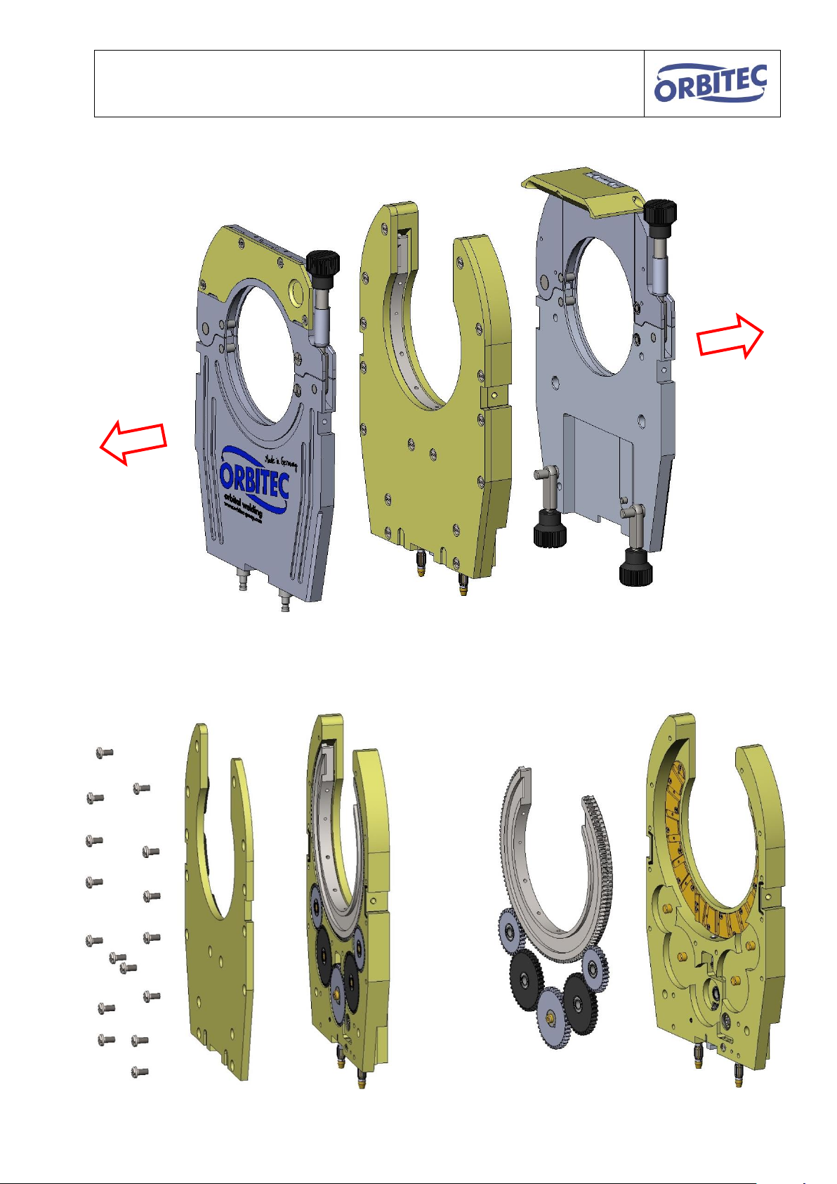
Operating instructions for OSK series S / G
You can now take off the clamping shell housing
C. Open the cover of the body and remove the rotor, gear wheels and gearbox
combination.
23
Page 24
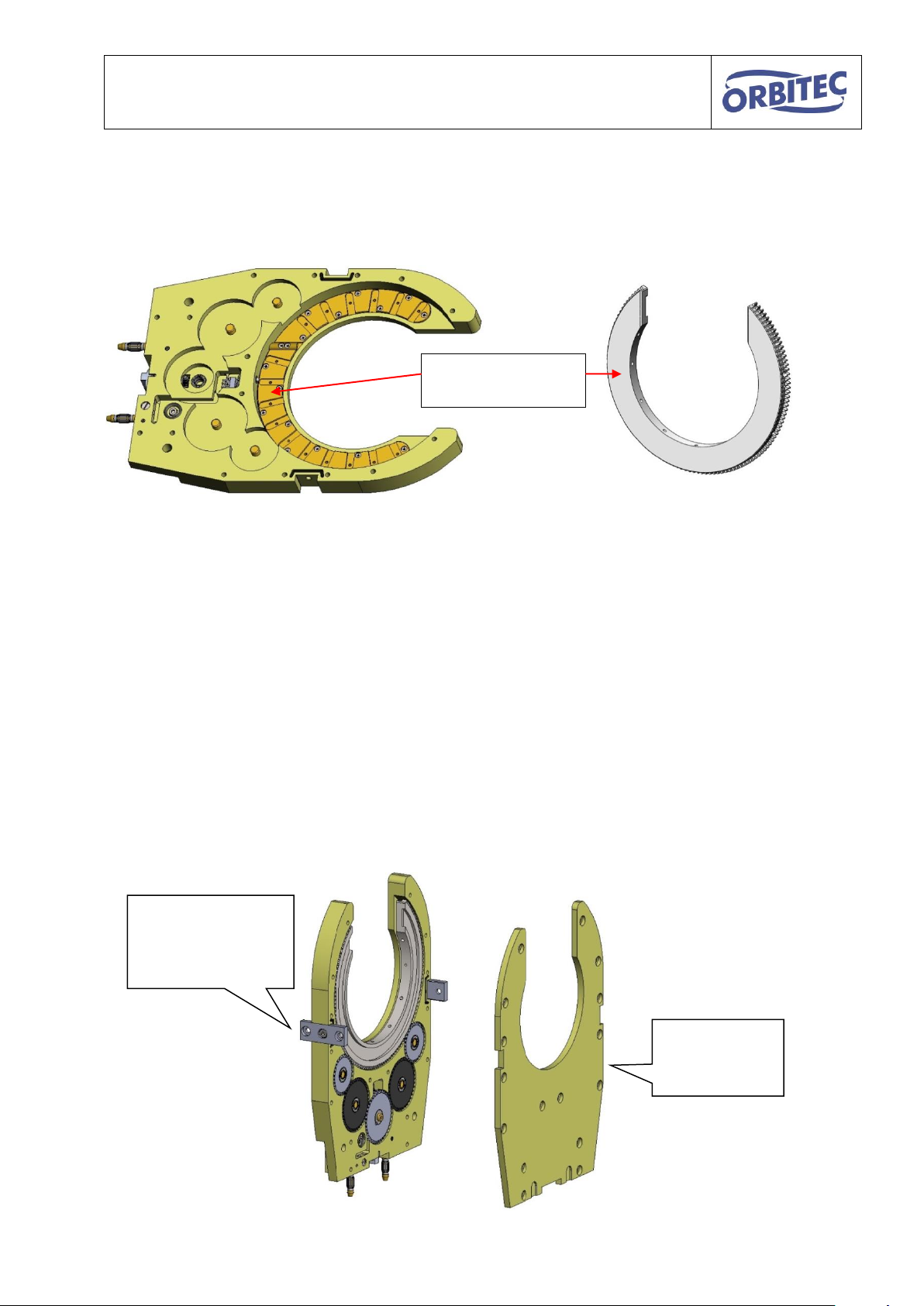
Operating instructions for OSK series S / G
1.
Install mounting
pass rails
2.
Install
cover
Clean contact areas
with fleece
d. Clean the individual disassembled parts to remove welding beads, soot and other
contamination.
Clean the contact areas of power transmission and rotor with fleece (Item. no.
1.1.4125)
Clean and degrease all individual parts as well as the body with isopropyl or benzine
and then blow out with compressed air.
e. Check the individual components for damage and, if necessary, replace damaged
parts
f. Completely reassemble the welding head.
Do not use fats or other lubricants.
Assemble the mounting pass rails before the body cover
(The body cover is aligned by the mounting pass rails, thereby the concentricity of the rotor is
ensured.)
Please ensure that the body and clamping shell housing are assembled gap-free (ambient air
impairs the quality of the welding seam).
24
Page 25
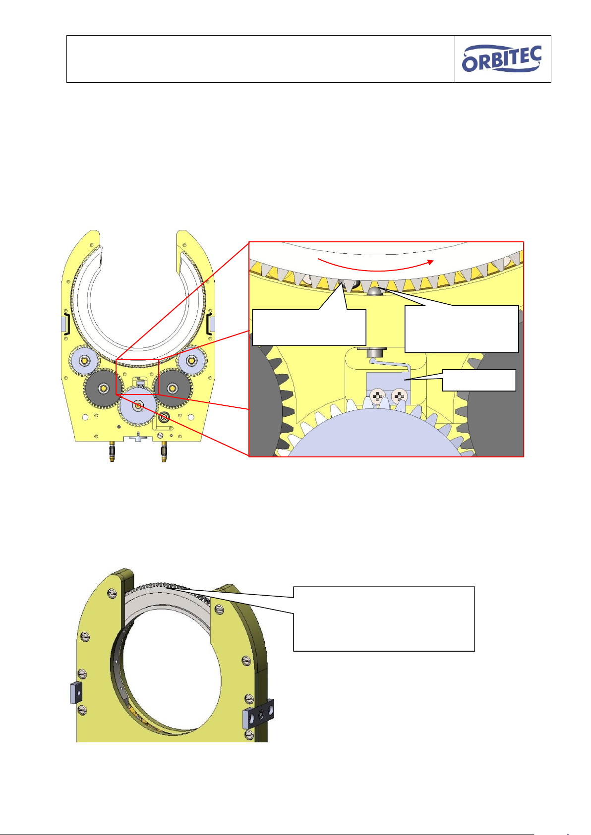
Operating instructions for OSK series S / G
end switch
pressure pin
(can not be
adjusted)
end switch cam
(adjustable)
As soon as the end switch cam activates the end
switch, the control registers the starting position and
the rotor stops.
Align the rotor via the control as
depicted, so that the end switch
cam can be reached
8.3. Setting the end switch cam
The end switch cam is already set at the factory. In the event that it needs to be readjusted,
proceed as follows:
The adjustment is carried out in fully assembled condition, the following illustration shows
schematically the function of the end switch.
To adjust the end switch, carry out the following work steps:
25
Page 26
Operating instructions for OSK series S / G
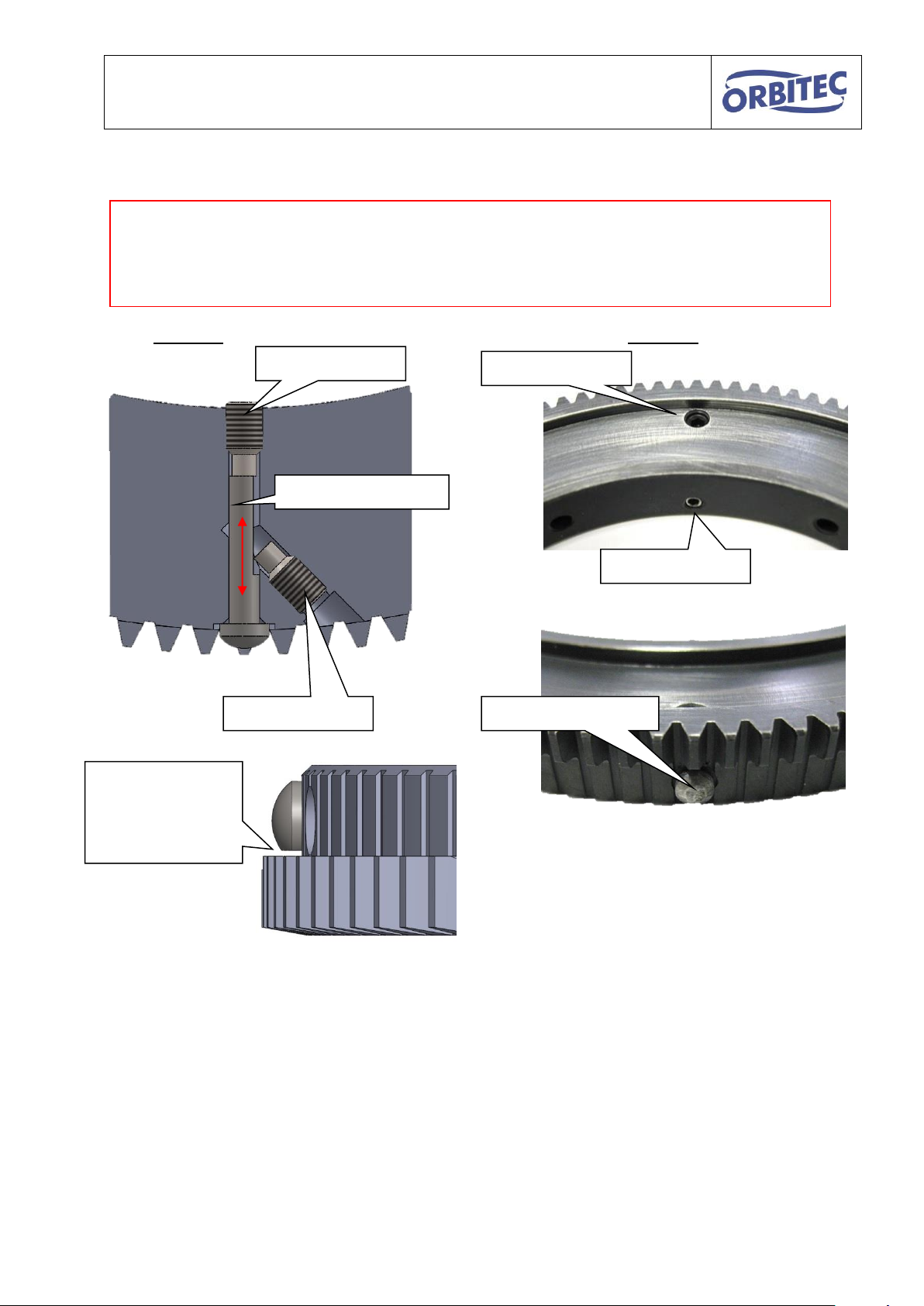
Variant A
Variant B
Clamping screw
end switch cam
Adjusting screw
end switch cam
Adjusting screw
Clamping screw
The flat side of
the tip points
towards the
interlocking
Attention!
Slowly approach the end switch.
Adjust only in 0.1mm steps.
An end switch cam protruding too far can damage the body and pressure pin.
Set the end switch cam with the adjusting screw and clamping screw.
Carry out a test run without an electric arc.
If the end switch is not activated, continue to adjust.
26
Page 27
Operating instructions for OSK series S / G
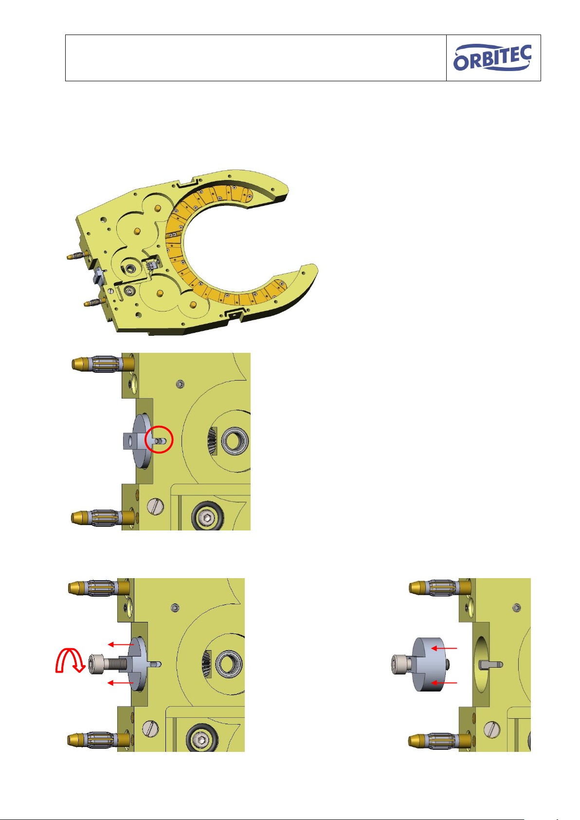
Disassemble the welding head as
shown (see disassembly for
cleaning).
Remove the threaded pins from
the coupling.
(2 are offset by 90°)
The coupling can be
pulled off with a screw
M4.
8.4. Exchange of the drive shaft
The drive shaft can be exchanged as follows.
27
Page 28
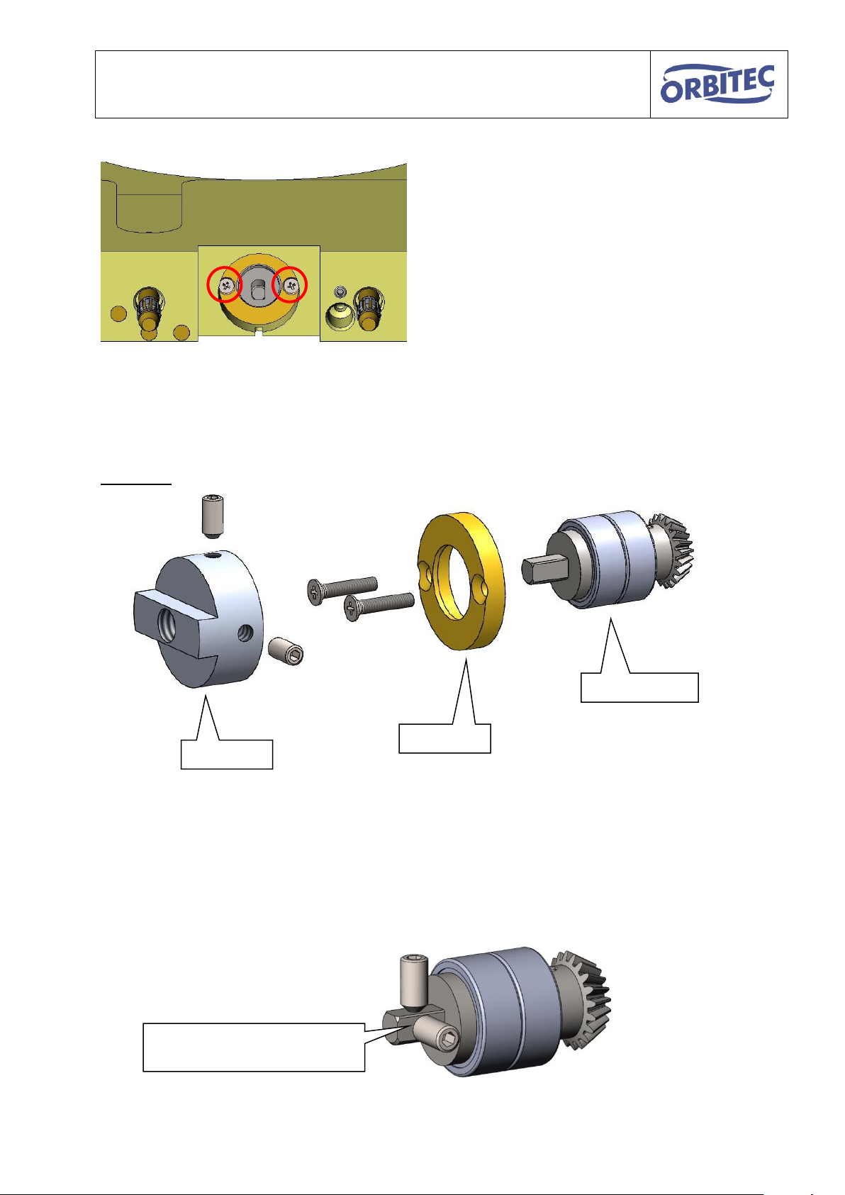
Operating instructions for OSK series S / G
Remove both screws of
the fixing.
Fixing
Drive shaft
Coupling
Tension on flattened areas
(Remaining components hidden)
Now you can pull out the drive shaft!
Summary:
Do not dismantle the drive shaft.
Use only original Orbitec drive shafts.
Tighten the threaded pins of the coupling only on the intended flattened areas of the drive
shaft.
28
Page 29
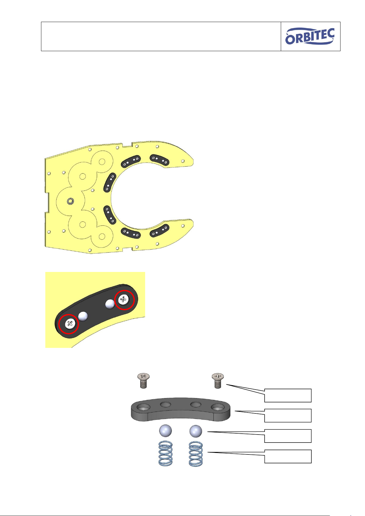
Operating instructions for OSK series S / G
Disassemble the cover as shown
Disassemble the damaged graphite nodules
by removing the screws.
Graphite
Ball
Spring
Screw
8.5. Exchange of graphite nodule
The graphite nodules ensure that the rotor can turn freely a they centre it in the middle.
The balls in the graphite nodules press the rotor to the current loop and thereby ensure the
power transmission.
The graphite nodules can be exchanged as follows.
Assembly of a graphite nodule:
29
Page 30

Operating instructions for OSK series S / G
Lay the rotor so that the graphite
nodules are lying in the guide
slot.
Carry out circular movements with
the rotor to align the graphite
nodules
Tighten the graphite nodules, while the screw only projects
as far as necessary from the rotor.
Attention!
Use torque wrench: 20 cNm
Correctly insert the new graphite nodules only slightly tighten the screws.
30
Page 31
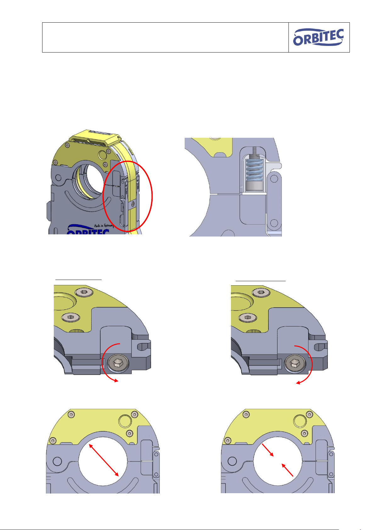
Operating instructions for OSK series S / G
Oversized pipe
Undersized pipe
The clamping range increases
The clamping range decreases
8.6. Setting of tension lock
OSK 21 CW and OSC 38 CV are fitted with space saving tension locks.
In case of under- or oversized pipe, if necessary ,readjustments can be made with the
adjusting screw to ensure a safe tightening.
31
Page 32

Operating instructions for OSK series S / G
Company logo
Address
Email address
Homepage
Follow operating
instructions
CE sign
Adhere to
warning signs
Tool type
Tool code for
control
Serial number
Item number
9. Type plate key
32
Page 33

Operating instructions for OSK series S / G
The ORS 115 enables:
Cut surfaces at Right-angle and
without offset
No deformations on pipes due to
concentric clamping
A fast and simple cutting process
Planfix 40 and Planfix 115 enable:
Finishing of the pipe ends for an even
better surface quality.
The clamping prisms enable:
A simple and fast centering of the
pipes, to set a welding spot.
10. Accessories (available separately)
1.2.4503 tube saw ORS 115
1.3.4101 Planfix 40
1.2.4005 Planfix 115
1.2.0129 prism DA 5 - 30 mm
1.2.0130 prism DA 10 – 65 mm
1.2.0131 prism DA 20 – 115 mm
33
Page 34

Operating instructions for OSK series S / G
11. Legal notices
ORBITEC GmbH does not assume any liability in case of inappropriate or incorrect use
of the product. The choice and application of the product are exclusively the responsibility
of the persons acting.
Warranty claims and claims arising out of any guarantees ORBITEC GmbH has provided
for this product are forfeited, if the product is not operated, maintained or serviced in
accordance with the operating instructions.
Exclusively original spare parts by ORBITEC GmbH must be used. Modifications to the
product or to individual components result in loss of warranty.
ORBITEC GmbH assume liability exclusively for maintenance and repair works carried
out by ORBITEC GmbH itself.
Orbitec GmbH reserves the right to make changes for the purpose product improvement
anytime without prior notice.
34
Page 35

Operating instructions for OSK series S / G
Hiermit bescheinigen wir, dass die nachfolgend
beschriebene Maschine allen einschlägigen
Bestimmungen der Richtlinie für Maschinen
2006/42/EG entspricht. Die Maschine entspricht
weiterhin allen Bestimmungen der Richtlinien über
elektrische Betriebsmittel 2006/95/EG und über die
elektromagnetische Verträglichkeit 2004/108/EG. Im
Falle von Veränderungen, Reparaturen die nicht
ausdrücklich von Orbitec autorisiert sind, verliert diese
Erklärung ihre Gültigkeit.
We hereby certify that the machine described below
complies with all relevant provisions of Machinery
Directive 2006/42 / EC.The machine corresponds to
continue 2004/108 / EC all the provisions of the
directives on electrical equipment 2006/95 / EC and
relating to electromagnetic compatibility. This
declaration shall become null and void in the event of
modifications and repairs, not specifically authorised
by Orbitec.
Geräte-
bezeichnung
Gerätetyp
Serie OSK
Artikelnummer
Orbitec
Geschlossener
Schweißkopf
OSK 21 C/CW
OSK 38 C/CW
OSK 53 G/GW
OSK 76 G/GW
OSK 115 G/GW
OSK 115 S/SW
1.3.2820/1.0.2820W
1.3.2920/1.0.2920W
1.3.2520/1.3.2599
1.3.2620/1.3.2699
1.3.2720/1.3.2799
1.1.2720/1.1.2720W
Description of
the machine
Type of machine
OSK Series
Item number
Orbitec
Enclosed Weld
Head
OSK 21 C/CW
OSK 38 C/CW
OSK 53 G/GW
OSK 76 G/GW
OSK 115 G/GW
OSK 115 S/SW
1.3.2820/1.0.2820W
1.3.2920/1.0.2920W
1.3.2520/1.3.2599
1.3.2620/1.3.2699
1.3.2720/1.3.2799
1.1.2720/1.1.2720W
12. EG-Konformitätserklärung
12. EC – Declaration of Conformity
Name des Herstellers: Orbitec GmbH
Name of manufacturer: (nachfolgend Orbitec genannt)
(In the following called Orbitec)
Anschrift des Herstellers: Orbitec GmbH
Address of manufacturer: Willi-Brehm-Str. 8
D – 63500 Seligenstadt - Germany
Zutreffende EG - Richtlinien: Niederspannungsrichtlinie (LVD) 2006/95/EG
Applicable EC Directives: Low Voltage Directive (LVD) 2006/95/EC
Angewandte harmonisierte Normen: DIN EN ISO 12100:2010
Harmonised standards applied: IEC 60974-1:2012 / EN 60974-1:2013-06
Andere Prüfungen : EMV- Testreport 281115- 2015 nach EN 60974-10:2014
Other tests :
Hersteller - Unterschrift: Seligenstadt, den 08.03.2016 Stefan Oßwald
Manufacturer's signature: (Geschäftsführer)
Managing Director
Richtlinie elektromagnet. Verträglichkeit (EMV)
2004/108/EG
Electromagnetic Compatibility (EMC) Directive 2004/108/EC
IEC 60974-3:2013 / EN 60974-3:2015-12
IEC 60974-7:2013 / EN 60974-7:2013-11
IEC 60974-10:2014 / EN 60974-10:2015-10
35
Page 36

Operating instructions for OSK series S / G
13. Notes
__________________________________________________________________________
__________________________________________________________________________
__________________________________________________________________________
__________________________________________________________________________
__________________________________________________________________________
__________________________________________________________________________
__________________________________________________________________________
__________________________________________________________________________
__________________________________________________________________________
__________________________________________________________________________
__________________________________________________________________________
__________________________________________________________________________
__________________________________________________________________________
36
Page 37

Operating instructions for OSK series S / G
__________________________________________________________________________
__________________________________________________________________________
__________________________________________________________________________
__________________________________________________________________________
__________________________________________________________________________
__________________________________________________________________________
__________________________________________________________________________
__________________________________________________________________________
__________________________________________________________________________
__________________________________________________________________________
__________________________________________________________________________
__________________________________________________________________________
__________________________________________________________________________
37
Page 38

Operating instructions for OSK series S / G
__________________________________________________________________________
__________________________________________________________________________
__________________________________________________________________________
__________________________________________________________________________
__________________________________________________________________________
__________________________________________________________________________
__________________________________________________________________________
__________________________________________________________________________
__________________________________________________________________________
__________________________________________________________________________
__________________________________________________________________________
__________________________________________________________________________
__________________________________________________________________________
38
Page 39

Operating instructions for OSK series S / G
__________________________________________________________________________
__________________________________________________________________________
__________________________________________________________________________
__________________________________________________________________________
__________________________________________________________________________
__________________________________________________________________________
__________________________________________________________________________
__________________________________________________________________________
__________________________________________________________________________
__________________________________________________________________________
__________________________________________________________________________
__________________________________________________________________________
__________________________________________________________________________
39
 Loading...