

Orbit Controls OC 505 Owner's Manual

OC505_GBM_21507
CALIBRATOR
MULTIMETER
OC 505
Owner’s Manual
ORBIT CONTROLS AG
Zürcherstrasse 137
CH-8952 Schlieren/ZH
Tel: + 41 44 730 2753
Fax: + 41 44 730 2783
e-mail: info@orbitcontrols.ch
www.orbitcontrols.ch

2
3
Stellen Sie sicher, dass Ihre Sendung das richtige Gerät, Orbit Controls Modell OC 505, beinhaltet,
einschliesslich einer Betriebsanleitung OC 505.
Vor dem Einschalten des Gerätes überprüfen Sie die Anschlüsse und die Versorgungsspannung. Ein
falsch angeschlossenes Gerät kann beschädigt werden und damit auch die mitverbundene
Folgeelektronik. Für falsche Handhabung wird jede Haftung abgelehnt.
Remove the Packing List and verify that you have received all equipment, including the following:
Orbit Controls Model OC 505 Handheld Calibrator.
Operator's Manual OC 505.
If you have any questions about the shipment, please call the Orbit Controls Customer Service
Department.
Shipment
- Calibrator-Multimeter Model OC505
- Charger 12V DC, 600mA
- Set of Cables 30cm with 4mm Banana and Crocodile.
- „K“ and „U“ Thermocouple Connector
- Owner’s Manual and Calibration Certificate
Vor dem Einschalten
ZU BEACHTEN
Dieses Gerät wurde sorgfältig verpackt. Falls es bei Ihnen in beschädigtem Zustand eintrifft,
benachrichtigen Sie unverzüglich den Orbit Controls Kundendienst (Tel: +41 44 730 2753 oder
Fax: +41 44 730 2783) und nehmen Sie einen Schadenrapport auf, welchen Sie auch von der
Transportgesellschaft unterschreiben lassen. Bewahren Sie bitte das Verpackungsmaterial für
eventuelle Reklamationen auf.
NOTE
When you receive the shipment, inspect the container and equipment for signs of damage. Note
any evidence of rough handling in transit. Immediately report any damage to the Orbit Controls
customer service, Phone +41 44 730 2753 or Fax +41 44 730 2783 and to the shipping agent.
The carrier will not honour damage claims unless all shipping material is saved for inspection. After
examining and removing contents, save packing material and carton in event the reshipment is
necessary.
Unpacking Instructions

4
INHALT
CALIBRATOR – MULTIMETER OC505 Page 5
1 OUTPUTS, INPUTS and KEYBOARD 6
2 GRAFIC DISPLAY 7
3 SPECIFICATIONS 7
3.1 CALIBRATOR 7
3.2 MULTIMETER 9
3.3 DATALOGGER 9
4 SELECTION-CALIBRATOR 10
4.1 DIRECT VALUE ENTRY 11
4.2 RAMPS 11
4.2.1 Ramp selection in Menu 11
4.3 RAMP STEPS 11
4.3.1 Selection of steps in Menu 11
4.3.2 Selection of individual steps 11
5 GRAFICS 12
5.1 GRAPHICS 12
5.2 TRANSIENTS 12
6 MENU STEPS 13
7 ADDITIONAL FUNCTIONS in the MULTIMETER MODE 14
7.1 ADDITIONAL FUNCTIONS 14
8 SOFTWARE CALIBRATION 14
8.1 CALIBRATION - CALIBRATOR 15
8.1.1 Calibration of Currents 15
8.1.2 Calibration of Voltages 15
8.1.3 Calibration of Resistors 16
8.2 CALIBRATION – MULTIMETER 16
9 HARDWARE 17
10 DATALOGGER 18
11 SOFTMANAGER OC505W 19
CALIBRATION CERTIFICATE 22
WARRANTY 23

5
CALIBRATOR - MULTIMETER OC 505
Current Calibrator 0/4 - 22mA, Source/Sink
Voltage Calibrator 0-25V
mV Outputs 0-27mV and 0-540 mV
DIN Thermocouples J, K, N, R, S, T, B, E
RTD Simulator Pt and Ni
Resistance Simulation to 3kOhm
Multimeter ±2V to ±200V DC and 0-100mA
Calibrates and Measures Simultaneously
Eight Memory slots for fast Transients
Graphics of Measurements
Steps, Ramps, direct value settings
Datalogger Function
OC505 is a Calibrator-Multimeter for generation of Currents 0-22mA Sink
or Source und Voltages to 25VDC. External voltages ±2V, ±20V and
±200VDC (firm ranges or auto ranging) and Currents to 0-100mA can be
measured simultaneously and shown at the display.
Further Functions contain generation of calibration mV Signals, Thermo voltages of DIN Thermocouples
and RTD Resistors and simulation of true resistors.
mV voltages of 0-27mV or 0-540mV are mainly used for calibration of Strain Gauges, Transmitters and
small signal inputs with resolution of up to 0.001mV.
Thermocouples J, K, N, R, S, T, B, E are simulated. The temperature is entered with the keyboard and
shown at the display. The cold junction is compensated to the ambient temperature. It can also be
switched-off.
RTD Thermometers can be simulated within the DIN temperature range. The temperature is entered with
the keyboard and shown at the display.
Ohm Source Resistance values up to 3kOhm are simulated. The resistance value is entered with the
keyboard and shown at the display.
Graphics and Memorising of measured signals is a standard function. The signals are continuously
stored and shown at the display as graphics. In apart of this eight memory slots for storing of fast signals
-Transients- are available. They can individually be stored and selectively recalled at the display.
Datalogger is an Option. The calibrating signals and the multimeter input are shown at the display and
stored as tables with date and time from internal RTC. They can be downloaded to the PC and edited
under Windows and Excel. A software program is available for Windows.
6
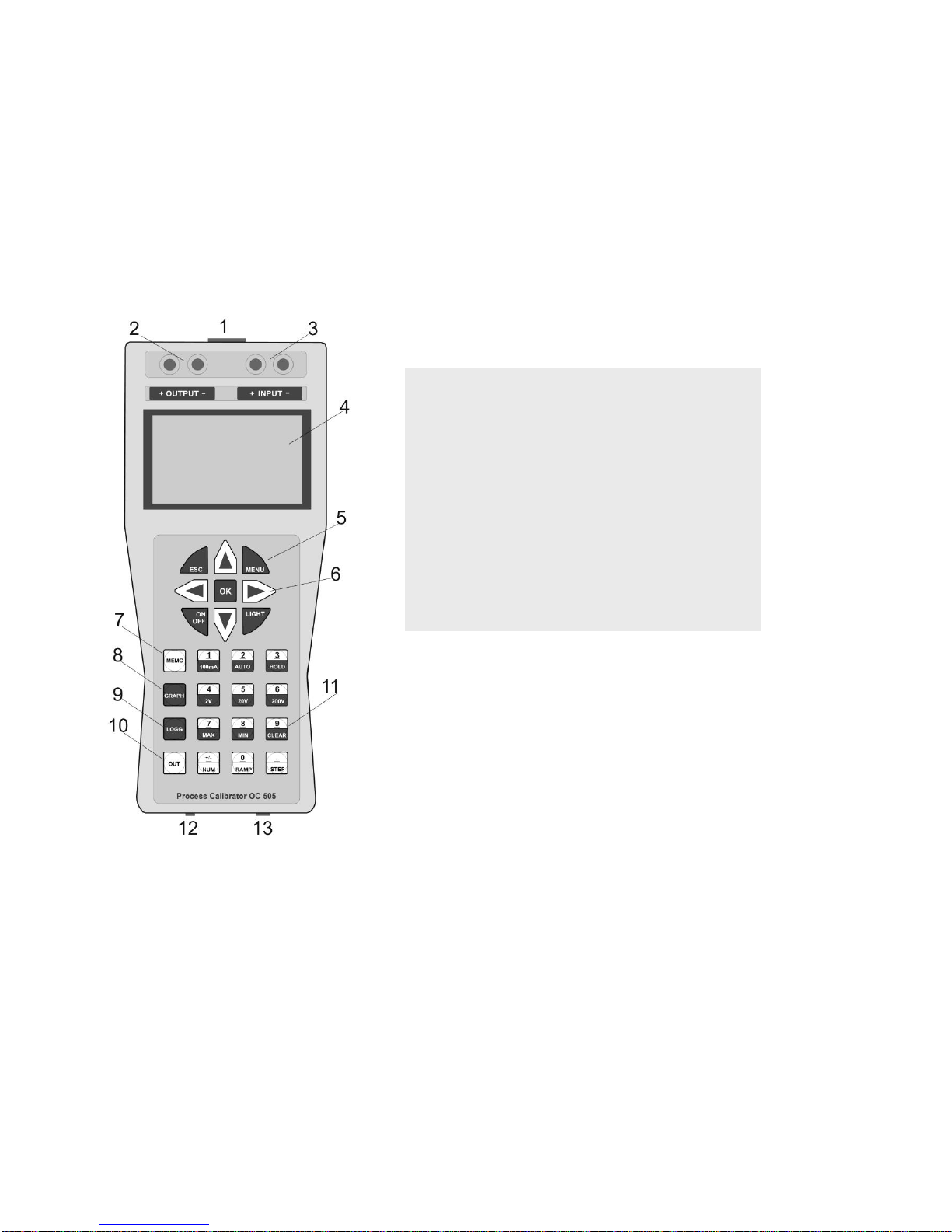
1 INPUTS, OUTPUTS and KEYBOARD
CALIBRATOR
Voltage and Current Outputs,
Resistance and RTD: + OUTPUT -
Thermocouples: Cu Terminals at the front
MULTIMETER
Voltage and Current Inputs: + INPUT -
CONTROLLER
The Functions of the Calibrator and the Multimeter are selected with the keyboard and supported by a
microcontroller. The factory settings and the calibrated points are stored in a nopn-volatile memory and
remain stored also when the instrument is switched off. The software calibration of all ranges is
accessible in the calibration menu and protected with a password. All ranges can be recalibrated via the
keyboard if required.
The graphic display is divided into two windows. The upper window is shows the multimeter functions,
the lower window the calibrator. In programming mode the display shows the parameters. In graphics
mode of operation the display shows the stored input signals.
1 Thermocouples Connector
2 Output Calibrator
3 Input Multimeter
4 LCD-Display
5 Main Keys
6 Cursor Keys
7 Memory Key
8 Recall Graphics
9 Datalogger
10 Selection of Calibrator Output Mode
11 Function Keys
12 Charger Jack
13 USB
7
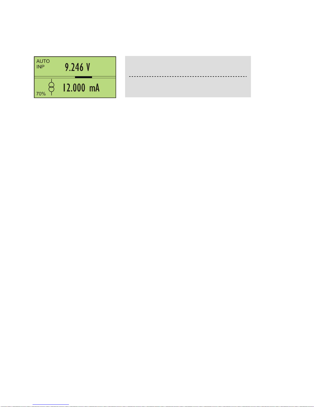
2 GRAPHICS DISPLAY
The LCD Display is divided into two parts. The upper part is for the multimeter functions, the lower part
for the calibrator. The bargraph in the middle is the analogical representation of the measured input
signals. The left side shows various symbols:
Symbols in the upper display part
AUTO Automatic Voltage Range or firm measuring range
200V Measure Ranges 2V, 20V, 200V, 100mA
INP The display shows the input signal.
Symbols in the lower display part
RMP Automatic Ramp of the calibrator signal
SUP The battery is being charged
60% Battery voltage in %. Do not run the instrument when the battery shows 0%. Charge only
with the enclosed original charger.
3 SPECIFICATIONS
3.1 CALIBRATOR Voltage and Current: + OUTPUT –
Thermocouples: Cu Connector
Conversion: 16 Bit
Current Source Range 0 ... 22mA. Maximum external Shunt 750 Ohm
Accuracy ± (0.05% from Value + 0.1% from Range)
Resolution 0.001 mA
Current Sink Range 0 ... 22mA at 24V maximum
Accuracy ± (0.05% from Value + 0.1% from Range)
Resolution 0.001 mA
Voltage Source Range 0 ... 25 V, 0 … 560mV, 0 … 28mV
Accuracy ± (0.05% from Value + 0.1% from Range)
Resolution: 0…25.000V, 0…560.00mV, 0…28.000mV
Load: 0 - 25V maximum 1mA
0 - 560mV, 0 - 28mV: maximum load 1kOhm
Thermocouples According to ITS 90:
J (1200 ºC), K (1370 ºC), N (1300 ºC), R (1760 ºC),
S (1760 ºC), T (400 ºC), B (1820 ºC), E (1000 ºC).
Accuracy ± 0.3 … 2.5 ºC
Resolution 0.1ºC
Load: maximum load 1kOhm
Could Junction compensation with SMT160 can be menu calibrated.
MULTIMETER measured input voltage in
automatic range.
CALIBRATOR generates 12.000mA. The Battery
has 70% of capacity.
 Loading...