

Page 1

Operating instructions
For responsible bodies and persons using the machine
Orbital Welding Power Supply
ORBIMAT 180 SW
Machine No.:
Code 850 060 202 | EN | Translation of original o perating instr uctions
To ensure safe working read the operating
instructions before commissioning.
Retain the operating instructions
for future reference.
Page 2

All rights reserved, in particular the rights of duplication and distribution as well as translation. Duplication and reproduction in any form (print, photocopy, microfilm or electronic) require the written permission of Orbitalum Tools GmbH.
Page 3

ORBIMAT 180 SW | Operating instructions
(17.09.18) OW_ORBIMAT_180SW_BA_850060202_00_EN orbitalum tools Gmb H, D-78224 Singe n, www.orbi talum.com, Ph one +49 (0) 77 31 792-0 3
1. About these instructions ......................................5
1.1 Warning messages .....................................5
1.2 Further symbols and displays .....................5
1.3 Abbreviations ............................................5
1.4 Further applicable documents ....................5
2. Information and safety instructions ......................6
2.1 Requirements for the responsible body .......6
2.2 Using the machine .....................................6
2.2.1 Proper use .......................................6
2.2.2 Machine constraints .........................7
2.3 Environmental protection/disposal .............7
2.3.1 Coolant ............................................7
2.3.2 Electric tools and accessories ...........7
2.4 Personnel qualification ..............................7
2.5 Fundamental information on operational
safety ........................................................8
2.6 Personal protective equipment ...................8
2.7 Remaining risks .........................................8
2.7.1 Injury through high weight ...............8
2.7.2 Burns and danger of fire through
high temperatures ...........................9
2.7.3 Tripping over the hose package ........9
2.7.4 Long-lasting physical damage
through wrong posture .....................9
2.7.5 Electric shock ..................................9
2.7.6 Danger through incorrect handling
of pressure tanks ........................... 10
2.7.7 Damage to eyes through radiation .. 10
2.7.8 Dangers through electromagnetic
fields ............................................. 10
2.7.9 Risk of suffocation through an
excessive argon share in the air ...... 11
2.7.10 Health problems ............................11
2.7.11 Danger of system tipping over ........11
2.7.12 Danger of explosion and fire ........... 11
2.7.13 General injuries through tools ........11
3. Description ........................................................12
3.1 ORBIMAT 180 SW .....................................12
3.2 Operating concept ....................................14
3.2.1 Operation via push switches
(softkeys) ......................................14
3.2.2 Operation via touch screen .............14
3.2.3 Operation via rotary knob...............14
3.2.4 Operation via an external
keyboard .......................................15
3.3 Warning signs ..........................................16
4. Scope of application...........................................17
4.1 Accessories .............................................17
4.1.1 ORBICAR W trolley..........................17
4.1.2 ORBICOOL Active ...........................17
4.1.3 ORBITWIN switching unit ................18
4.1.4 ORBmax oxygen meter ................... 18
4.1.5 Remote control with cable ..............18
4.1.6 OCL-30 coolant ............................... 18
4.1.7 ORBIPURGE forming set..................18
4.1.8 Paper rolls and ribbon cartridges ...18
5. Technical specifications .....................................19
6. Storage and transport ........................................20
6.1 Gross weight ............................................20
6.2 Preparing storage ....................................20
6.2.1 Removing the weld head from the
orbital welding power supply ..........20
6.2.2 Pumping out coolant ......................20
7. Commissioning ..................................................23
7.1 Scope of delivery .....................................23
7.2 Checking the scope of delivery .................23
7.3 Accessories (optionally available) .............23
7.4 Connecting the welding power supply .......24
7.4.1 Setting up machine ........................24
7.4.2 Connecting a gas bottle .................24
7.4.3 Connecting weld heads ..................25
7.4.4 Detaching coolant hoses ................25
7.4.5 Pumping out coolant ......................25
7.4.6 Closing off gas hose .......................25
7.5 Commissioning ........................................25
7.5.1 Topping up coolant .........................26
7.5.2 Connecting Remote control/dummy
plug ...............................................26
7.5.3 Switching on the power source .......27
7.5.4 Setting the language ......................28
7.5.5 Setting the measuring units ...........28
8. Operation ..........................................................29
8.1 Auto programming ...................................29
8.1.1 Setting parameters ........................29
8.1.2 Configuring weld head ...................29
8.1.3 Configuring material ......................30
8.1.4 Configuring protective gas .............30
8.1.5 Configuring pipe diameter ..............31
8.1.6 Configuring wall thickness .............31
8.1.7 Configuring wire feed .....................31
8.1.8 Calculating procedure ....................31
8.2 Testing the procedure ...............................32
8.2.1 Preparing weld head ......................32
8.2.2 Preparing electrode .......................32
8.2.3 Turning weld head ..........................32
8.2.4 Connecting forming gas .................34
8.2.5 Welding .........................................34
8.2.6 Interrupting the welding process ....36
8.3 Adjusting the procedure ...........................37
8.3.1 Reasons and steps for adjusting
procedure ......................................37
8.3.2 Making percental changes ..............37
TABLE OF CONTENTS
Page 4

ORBIMAT 180 SW | Operating instructions
4
orbitalum tools GmbH, D-78224 Sing en, www.or bitalum.com, P hone +49 (0) 77 31 792-0 (17.09.18) OW_OR BIMAT_180SW_ BA_850 060202_00 _EN
8.3.3 Adjusting individual parameters .....38
8.3.4 Digital gas management.................38
8.3.5 Adjusting gas times .......................38
8.3.6 Adjusting ignition current, final
current and current slope-off ..........39
8.3.7 Adjusting the pool formation time ..39
8.3.8 Adjusting welding current and
transition times ("Slope") .............. 40
8.3.9 Adjusting pulse times ....................41
8.3.10 Adjusting weld speed and
transition time ("Slope") ................42
8.3.11 Changing the sector ...................... 44
8.4 Saving and calling up a procedure ........... 46
8.4.1 Saving a procedure ....................... 46
8.4.2 Calling up a procedure .................. 46
8.5 Locking machine with a login .................... 47
8.6 Tacking function ...................................... 48
8.7 Using the second gas pressure level
("Flow Force") ..........................................49
8.8 Connecting supplementary devices ..........51
8.8.1 ORB Residual Oxygen Meter ........... 51
8.8.2 Connecting and configuring the
BUP control unit ............................. 51
8.8.3 TIG manual welding torch ...............51
8.8.4 External remote control .................. 53
8.8.5 External printer (A4) .......................53
8.8.6 External monitor /HDMI ................. 53
8.9 Monitoring functions ................................ 53
8.9.1 General information ....................... 53
8.9.2 Adjusting limit values .....................54
8.10 Data documentation and data
management ............................................55
8.10.1 Managing data ............................... 55
8.10.2 Entering comments and application
data ("Process details") .................57
8.10.3 Working using USB ........................58
8.10.4 Viewing and printing data ..............59
8.10.5 Editing data on a PC with the
"OrbiProgCA" supplementary
software ....................................... 60
8.11 Updating and backup functions for the
software ................................................. 60
8.12 Updating software components ................ 61
8.13 Saving software components ...................61
8.14 Restoring software components ...............61
8.15 Working in other languages ...................... 61
8.15.1 Changing the language ..................61
8.15.2 Printing data in another language ...62
8.15.3 Creating a new operating
language .......................................62
8.16 Importing programs from other
Orbitalum power sources .........................62
8.16.1 Impor ting procedures ..................... 63
8.17 Special keyboard commands ....................63
8.18 Operation of the system with other mains
voltages ...................................................63
9. Service and troubleshooting .............................. 64
9.1 Performing service work .......................... 64
9.1.1 Pumping out coolant ..................... 64
9.1.2 Performing motor calibration ......... 64
9.1.3 Adjusting an external printer ......... 66
9.1.4 Switching on an internal printer ..... 66
9.1.5 Printing a test page ........................67
9.1.6 Service screen ...............................67
9.1.7 Info............................................... 68
9.2 Possible application/operating errors ...... 68
9.2.1 Uneven weld seam ("current
fluctuations") ............................... 68
9.2.2 Annealing colors inside/outside .... 68
9.2.3 Wide seam and no weld
penetration .................................... 69
9.2.4 Uneven seam/hole formation at
the end of welding .........................69
9.2.5 Ignition problems ...........................70
9.2.6 Machine does not start ..................70
9.3 List of error messages ..............................71
9.4 Status LED indicators ...............................75
9.5 Temporarily deactivating sensors and
monitoring functions ................................ 75
9.5.1 Sensors .........................................75
9.5.2 Monitoring limits ...........................75
9.5.3 External input for aborting .............75
9.6 Setting the date and time ......................... 76
10. Maintenance and troubleshooting ......................77
10.1 Instructions for care .................................77
10.2 Maintenance and care ..............................77
10.2.1 Storage..........................................78
10.3 Servicing/Customer service ......................78
11. EC Declaration of Conformity ....................79
Page 5
ORBIMAT 180 SW | Operating instructions About these instructions
(17.09.18) OW_ORBIMAT_180SW_BA_850060202_00_EN orbitalum tools Gmb H, D-78224 Singe n, www.orbi talum.com, Ph one +49 (0) 77 31 792-0 5
1. ABOUT THESE INSTRUCTIONS
1.1 Warning messages
The warning messages used in these instructions warn you of injuries or damage to property.
Always read and observe these warning messages!
This is the warning symbol. It should warn you against dangers of injury. In order to avoid injuries or
death observe the measures marked with a safety sign.
WARNING LEVEL MEANING
DANGER!
Imminently hazardous situation that results in death or serious injuries if the safety measures are
not observed.
WARNING!
Potentially hazardous situation that may result in death or serious injuries if the safety measures
are not observed.
CAUTION!
Potentially hazardous situation that may result in slight injuries if the safety measures are not
observed.
NOTE! Potentially hazardous situation that may result in material damage if the safety measures are not
observed.
1.2 Further symbols and displays
SYMBOL MEANING
Important information for comprehension.
1.
2.
3.
...
Request for action in a sequence of actions: Action is required here.
Single request for action: Action is required here.
1.3 Abbreviations
ABBREVIATION MEANING
OM, SW ORBIMAT, Type "SmartWelder"
1.4 Further applicable documents
The following documents apply together with these operating instructions:
• Operating instructions of the orbital weld head
Page 6

Information and safety instructions ORBIMAT 180 SW | Operating instructions
6
orbitalum tools GmbH, D-78224 Sing en, www.or bitalum.com, P hone +49 (0) 77 31 792-0 (17.09.18) OW_OR BIMAT_180SW_ BA_850 060202_00 _EN
2. INFORMATION AND SAFETY INSTRUCTIONS
2.1 Requirements for the responsible body
Workshop/outdoor/field use: The responsible body is responsible for safety in the danger zone around the machine, and
should allow only qualified personnel to enter the zone or operate the machine in the danger zone.
Employee safety: The operator has to observe the safety regulations described in this chapter as well as has to work
safety-consciously and with all prescribed safety equipment.
The employer undertakes to give the employees clear notice of the dangers arising that are specified in the EMF directives and to evaluate the workplace correspondingly.
Requirements for special EMF evaluations with regard to general activities, working materials and workplaces*:
TYPE OF WORKING MATERIALS OR
WORKPLACE
EVALUATION REQUIRED FOR:
Employees without
particular risk
Employees at particular
risk (with the exception
of those with active im-
plants)
Employees with active
implants
(1) (2) (3)
Arc welding, manual (including MIG (Metal
Inert Gas), MAG (Metal Active Gas), TIG (Tungsten Inert Gas)) under observance of triedand-tested procedures and without physical
contact to the line
No No Yes
* According to Directive 2013/35/EU
2.2 Using the machine
2.2.1 Proper use
The orbital welding power supply is intended solely for the following utilization:
• Utilization in combination with an orbital weld head of the company Orbitalum Tools GmbH or with
a compatible third-part device in combination with a weld head adapter of the company Orbitalum
Tools GmbH.
• TIG welding of materials that are specified in these operating instructions (see chap. 4, p. 17).
• Empty unpressurized tubes that are free of contaminations, explosive atmospheres or liquids.
Intended use also includes the following points:
• Permanent supervision of the machine during operation. The operator must always be able to stop the process.
• Observing all safety instructions and warning messages in these operating instructions.
• Observing of the further applicable documents.
• Complying with all inspection and maintenance work.
• Use of the machine solely in its original state.
• Usage solely of original accessories as well as original spare parts and operating materials.
• Usage solely of protective gases that are classified for TIG welding process in accordance with EN ISO 14175.
• Usage solely of coolant OCL-30 of the company Orbitalum Tools GmbH.
• Checking of all the safety-relevant items and functions before commissioning.
• Processing of those materials named in the operating instructions.
Page 7

ORBIMAT 180 SW | Operating instructions Information and safety instructions
(17.09.18) OW_ORBIMAT_180SW_BA_850060202_00_EN orbitalum tools Gmb H, D-78224 Singe n, www.orbi talum.com, Ph one +49 (0) 77 31 792-0 7
• Purpose usage of all components involved in the welding processes as well as of all further factors that have an
influence on the welding process.
• Solely commercial usage.
2.2.2 Machine constraints
• The workplace can be in the tube preparation, in plant construction or in the plant itself.
• The machine is operated by one person.
• Erect the machine solely on a solid surface.
• A radial space requirement/freedom of movement of approx. 2 m around the machine is required for people.
• Work lighting: min. 300 Lux.
• Climate conditions: –10 °C to 40 °C; < 80% rel. humidity.
• Only work with the machine in dry surroundings (not in misty, rainy or stormy conditions). If appropriate use a welding tent.
• Cooling is only ensured with a full coolant tank.
2.3 Environmental protection/disposal
2.3.1 Coolant
Dispose of coolant in accordance with the local statutory regulations.
2.3.2 Electric tools and accessories
Used-up power tools and accessories contain a large amount of valuable raw materials and plastics which can be recycled.
(as per RL 20 02/96/EC)
• Used electronic devices marked with the adjacent symbol may not be disposed of with household waste in accordance with EU directives.
• By actively using the offered return and collection systems, you are doing your part to reuse and recycle used electronic devices.
• Used electronic devices contain parts that must be handled selectively according to the EU directive. Separate
collection and selective treatment are the basis for environmentally responsible disposal and protection of human
health.
• We will properly dispose of devices and machines from Orbitalum Tools GmbH purchased after August 13th, 2005
if they are sent to us postage-paid.
• In the case of used electronic devices which may represent a risk to human health or safety due to contamination
during use, we have the option of refusing return.
• The user is responsible for disposing of used electronic devices purchased before August 13th, 2005. Bitte wenden
Sie sich hierfür an einen Entsorgungsfachbetrieb in Ihrer Nähe.
• Important for Germany: Devices and machines of Orbitalum Tools GmbH may not be disposed of at communal
dumps, as they are only used in the commercial sector.
2.4 Personnel qualification
CAUTION!
The orbital welding power supply may only be used by instructed personnel.
• Minimum age: 18 years old.
• No physical impairments.
• Operation of the machine by underage persons only under supervision by a person authorized to issue instructions.
• A basic knowledge of TIG welding process is advisable.
Page 8

Information and safety instructions ORBIMAT 180 SW | Operating instructions
8
orbitalum tools GmbH, D-78224 Sing en, www.or bitalum.com, P hone +49 (0) 77 31 792-0 (17.09.18) OW_OR BIMAT_180SW_ BA_850 060202_00 _EN
2.5 Fundamental information on operational safety
CAUTION!
Observe valid safety and accident prevention regulations.
Improper usage can impair safety. This can result in life-threatening injuries.
X Never leave an welding power supply unattended when it is switched on.
X The operator has to ensure that no 2nd person is inside the danger zone.
X Do not modify or convert the orbital welding power supply.
X Use the orbital welding power supply only in proper operating order.
X Use only genuine tools, spare parts and accessories as well as specified operating materials.
X In case of changes in the operating behavior stop operation immediately and have the fault eliminated.
X Do not remove safety devices.
X In order to increase safety a customer-provided SPE-PRCD or a universal-current residual-current circuit-breaker 30
mA or an isolating transformer between the mains network and the welding power supply is required.
X Do not pull the machine at the hose package or the cable.
X Repair and maintenance work on the electrical equipment may only be carried out by a qualified electrician.
X Do not carry the machine by the hose package or the cable and do not use the machine to pull out the plug (except
in an emergency). Protect the cable against heat, oil and sharp edges (chips).
2.6 Personal protective equipment
The sole act of operating the welding power supply does not require personal protective equipment:
X When connecting and using a weld head observe the respective safety instructions and warning messages of the
weld head.
X Observe the remaining risks.
2.7 Remaining risks
2.7.1 Injury through high weight
The orbital welding power supply has a weight of 28 kg (61.73 lbs). A significant health hazard exists during lifting.
Danger of impact and crushing exists in the following situations:
CAUTION!
Falling of the orbital welding power supply during transportation or setting up.
CAUTION!
Falling of the orbital welding power supply caused by it being put down improperly.
X Use a suitable transport medium to transport the orbital welding power supply.
X Always use 2 persons to lift and remove the orbital welding power supply from the packaging.
X When lifting the machine do not exceed the permissible total weight of 25 kg for men and 15 kg for women.
X Place the orbital welding power supply on a stable base.
X Wear safety shoes.
Page 9

ORBIMAT 180 SW | Operating instructions Information and safety instructions
(17.09.18) OW_ORBIMAT_180SW_BA_850060202_00_EN orbitalum tools Gmb H, D-78224 Singe n, www.orbi talum.com, Ph one +49 (0) 77 31 792-0 9
2.7.2 Burns and danger of fire through high temperatures
CAUTION!
The orbital weld head is hot after welding. Very high temperatures arise in particular after several
consecutive welding processes. There is a danger of burns or damage to the points of contact when
working on the orbital weld head (for example when changing clamps or mounting/removing the electrodes). Materials without thermal resistance (for example foam inlay of the transport packages) can
be damaged when coming into contact with the hot orbital weld head.
X Wear safety gloves.
X Wait until the surfaces have cooled down to below 50 °C before working on the orbital weld head or before packing
into the transport packaging.
WARNING!
Thermal problems can arise in the case of incorrect positioning of the forming system or the use of
impermissible materials in the welding area. In the worst case a fire will be started. Observe the
local general fire protection measures.
X Position the forming system correctly.
X Use only permissible materials in the welding area.
WARNING!
Danger of scalding through hot emitted liquids as well as hot plug connections during heavy operation.
X Heed the safety precautions of the technical supervisor/person in charge of safety.
2.7.3 Tripping over the hose package
CAUTION!
If a hose package is connected, there is the danger that persons may trip over it and be injured.
WARNING!
Tripping over could cause the plug to be pulled out so that in the worst case an arc may arise between
the plug and the orbital weld system. Burns and glaring light may be the result.
X Ensure that under no circumstances can people trip over the hose package.
X Do not place the hose package under tension.
X Ensure that the hose package is connected properly and that the strain relief is attached.
2.7.4 Long-lasting physical damage through wrong posture
X Use the machine so that an upright and comfortable body position can be achieved during operation.
2.7.5 Electric shock
WARNING!
The danger exists of unintentionally operating the ignition function when connecting or disconnecting a weld head from the welding power supply.
X Switch off the orbital welding power supply when connecting or disconnecting a weld head.
X Do not play with weld head.
X If the weld head is not ready for operation, switch it to the "Test" function.
WARNING!
Electrical hazards through contact.
Page 10

Information and safety instructions ORBIMAT 180 SW | Operating instructions
10
orbitalum tools GmbH, D-78224 Sing en, www.or bitalum.com, P hone +49 (0) 77 31 792-0 (17.09.18) OW_OR BIMAT_180SW_ BA_850 060202_00 _EN
X Do not touch energized parts (workpieces), especially when igniting the arc.
X From the start of the welding process avoid contact with the tube and the housing of the orbital weld head.
X Wear dry safety shoes, dry metal-free (grommet-free) leather gloves and dry safety suits to minimize the electrical
hazard.
X Work on a dry surface.
DANGER!
Risk of death for people with heart problems or cardiac pacemakers.
X Do not allow persons with increased sensitivity to electrical hazards (e.g. weakness of the heart) to work with the
machine.
DANGER!
Danger of an electric shock in the case of improper reaching in into and opening of the machine.
X Allow only a professional electrician to access the electrical system.
DANGER!
The danger of an electric shock exists through non-compatible or damaged connectors.
X Do not use adapter plugs together with protectively grounded power tools.
X Ensure that the connecting plugs of the machine fit into the outlet.
X When connecting use a residual-current circuit breaker 30 mA.
2.7.6 Danger through incorrect handling of pressure tanks
WARNING!
Various injuries and damage to property.
X Heed safety regulations for pressure tanks.
X Heed safety data sheets for pressure tanks.
2.7.7 Damage to eyes through radiation
WARNING!
During the welding process infrared, glaring and ultraviolet rays arise that can seriously damage
the eyes.
X Keep the flip cover and swivel clamp closed during the welding process.
X During operation, wear eye protection to EN 170 and skin-covering safety clothing.
X At closed weld heads ensure proper working order of the eye protection.
2.7.8 Dangers through electromagnetic fields
DANGER!
Depending on the form of the workplace life-threatening electromagnetic fields can arise in the direct
vicinity.
X People with heart problems or cardiac pacemakers may not operate the welding system.
X The operator has to ensure safe design of the workplace in accordance with the EMF Directive 2013/35/EU.
X Use only electrical devices with protective insulation in the working area of the welding system.
X Observe electromagnetically-sensitive devices when igniting the system.
Page 11

ORBIMAT 180 SW | Operating instructions Information and safety instructions
(17.09.18) OW_ORBIMAT_180SW_BA_850060202_00_EN orbitalum tools Gm bH, D-78224 Sin gen, www.or bitalum.com , Phone +49 (0) 77 31 792-0 11
2.7.9 Risk of suffocation through an excessive argon share in the air
DANGER!
If the argon share in the air rises above 50%, lasting damage or risk of death can arise suffocation.
X Ensure sufficient ventilation in rooms.
X If necessary, monitor the oxygen level in the air.
2.7.10 Health problems
WARNING!
Poisonous vapors and substances during the welding process and handling of the electrodes!
X Use extraction devices in accordance with the professional association regulations (e.g. BGI: 7006-1).
X Extra caution is required with chrome, nickel and manganese.
X Do not use electrodes containing thorium.
2.7.11 Danger of system tipping over
WARNING!
Manifold injuries and damage to property through system (for example ORBICAR welding carriage,
gas bottle, welding power supply, cooling unit) tipping over from the application of force from outside!
X Set up the machine so that it stands securely against external influences.
X Keep moving masses at least 1 meter away from the machine.
2.7.12 Danger of explosion and fire
DANGER!
Danger of explosion and fire through flammable materials near the welding zone or solvent in the
room air.
X Do not weld near solvents (for example where painting is being carried out) or explosive substances.
X Do not use flammable substances as a base in the welding area.
X Ensure that no flammable materials or soiling is located near the machine.
2.7.13 General injuries through tools
CAUTION!
Injuries can occur during dismantling for the proper disposal of the orbital welding power supply
through uncertainties in handling tools.
X In case of uncertainties send the orbital welding power supply to Orbitalum Tools – proper disposal is carried out
here.
Page 12

Description ORBIMAT 180 SW | Operating instructions
12
orbitalum tools GmbH, D-78224 Sing en, www.or bitalum.com, P hone +49 (0) 77 31 792-0 (17.0 9.18) OW_OR BIMAT_180SW_ BA_850 060202_00_ EN
3. DESCRIPTION
3.1 ORBIMAT 180 SW
1
4
2
5
6
7
8 9 10 11 12 13 14 15 16 17 18 19
20
3
26
27
31
32
2524
28
29
30
21 2322
33
34
Page 13

ORBIMAT 180 SW | Operating instructions Description
(17.09.18) OW_ORBIMAT_180SW_BA_850060202_00_EN orbitalum tools GmbH , D-78224 Singen , www.orbi talum.com, Pho ne +49 (0) 77 31 792-0 13
ITEM DESIGNATION FUNCTION
1 Color touch display Operating the welding power supply, see chap. 3.2, p. 14
2 Push switches (softkeys) Operating the welding power supply, see chap. 3.2, p. 14
3 Cover, hinged Protects the operating elements
4 Connection socket, "USB", front Connection possibility for USB devices (2x) (optional)
5 Integrated system printer For printing actual values and welding data reports
6 Rotary knob Operating the welding power supply, see chap. 3.2, p. 14
7 Carry handles Transporting the welding power supply
8 Main switch (green) Switch on the welding power supply; lights up green during operation
9 Off button (red) Switch off the welding power supply; lights up red during operation and
in "Stand-by" mode
10 Connection socket "BUP" Connection possibility for "BUP Control Box", forming gas pressure con-
troller (optional)
11 Connection socket "ORBmax" Connection possibility for "ORBmax", residual oxygen meter (optional)
12 Connection socket "Remote" Connection for remote external control (optional) or dummy plug
13 Connection socket "Weld head" Connection for weld head signal line
14 Connection socket "Gas" Connection for gas hose to the weld head
15 Coolant connection, blue Connection for coolant supply line
16 Eye, strain relief Strain relief weld head to the power source
17 Coolant connection, red Connection for coolant return line
18 Weld current socket Connection weld head
19 Weld current connection Connection weld head
20 Ventilation slot Venting the welding power supply
21 Connection socket "LAN", rear Connection possibility for LAN cable
22 Connection socket "USB", rear Connection possibility for USB devices (2x) – see Item 4
23 Connection socket "HDMI", rear Connection possibility for HDMI cable
24 Coolant level indication Indicates the fill level of the coolant in the tank
25 Tank opening with lid Holding of up to 2.2 liter coolant for cooling the connected weld tongs
and heads
26 Rating plate Indication of the machine data
27 Gas connection Weld gas input
28 Connection socket "External cooling" Connection of external cooling unit signal line
29 Connection socket "ORBITWIN" Connection for ORBITWIN Switching Unit
30 Power input socket Connection for power line
31 Connection socket Connection possibility superordinate control system
32 Connection socket Connection possibility CAN-compatible components
33 Surface for keyboard The optionally available keyboard can be placed before the softkeys.
34 LED display Display of operating states and coolant flow
Page 14
Description ORBIMAT 180 SW | Operating instructions
14
orbitalum tools GmbH, D-78224 Sing en, www.or bitalum.com, P hone +49 (0) 77 31 792-0 (17. 09.18) OW_OR BIMAT_180SW_ BA_850 060202_00 _EN
3.2 Operating concept
The main control elements are the 6 push switches, whose current function assignment is displayed at the bottom margin of the display, the touch screen and the rotary knob. Direct access to standard functions (e.g. "Start" and "STOP")
is always possible. The entry of text is optionally possible using a keyboard that can be connected externally. If faults
occur (e.g. failure of the rotary knob or softkeys), the machine can be operated completely using the external keyboard.
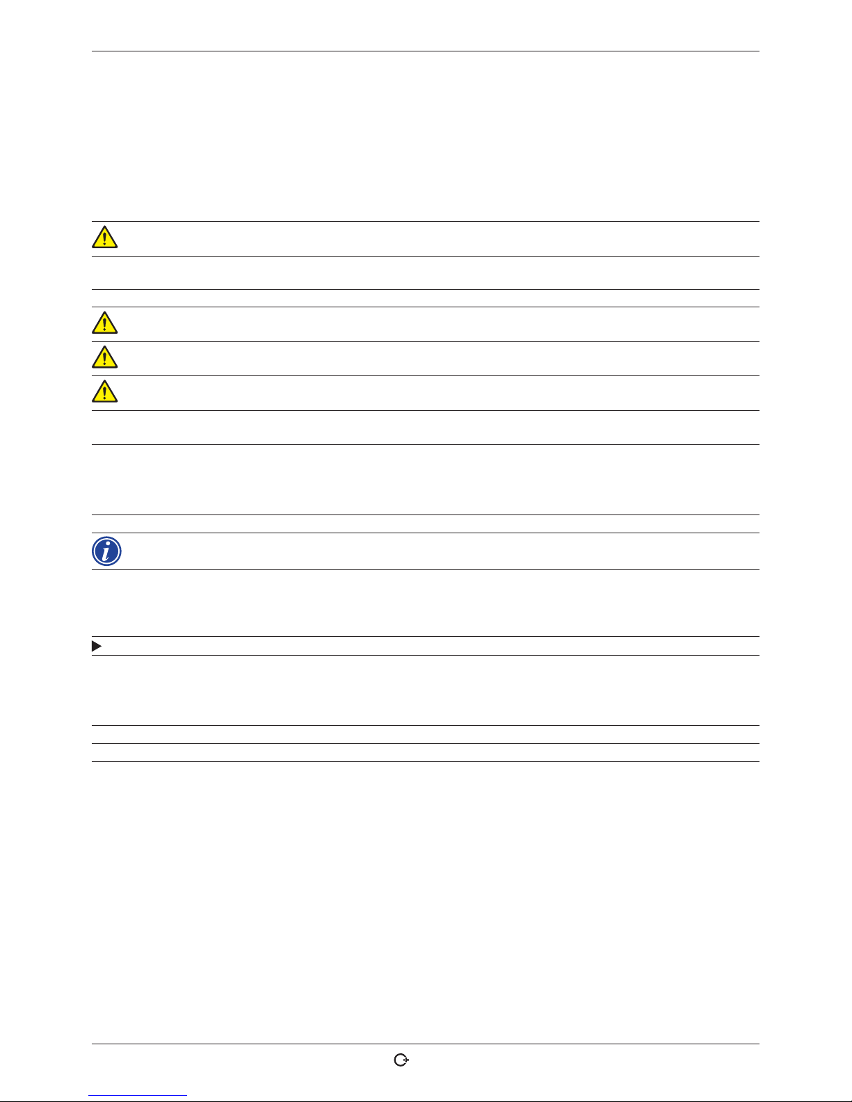
3.2.1 Operation via push switches (softkeys)
The five push switches (Items 1 - 6) are assigned with
standard functions as softkeys.
Examples:
The push switch (Item 6) is usually assigned the "Menu"
function, meaning pressing it brings you directly to the
main menu, regardless of which sub-menu currently appears in the display. The push switch
(Item 3) is assigned the "Save" function. This allows a procedure change to be saved rapidly.
1
2
3
4
5
6
3.2.2 Operation via touch screen
Rapid and efficient operation via touch screen. Directly
touch the values to be changed. A virtual keyboard is
displayed. Operation while wearing protective gloves only
possible to a limited extent and not recommended.
7
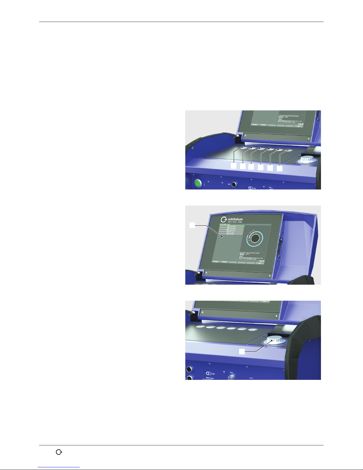
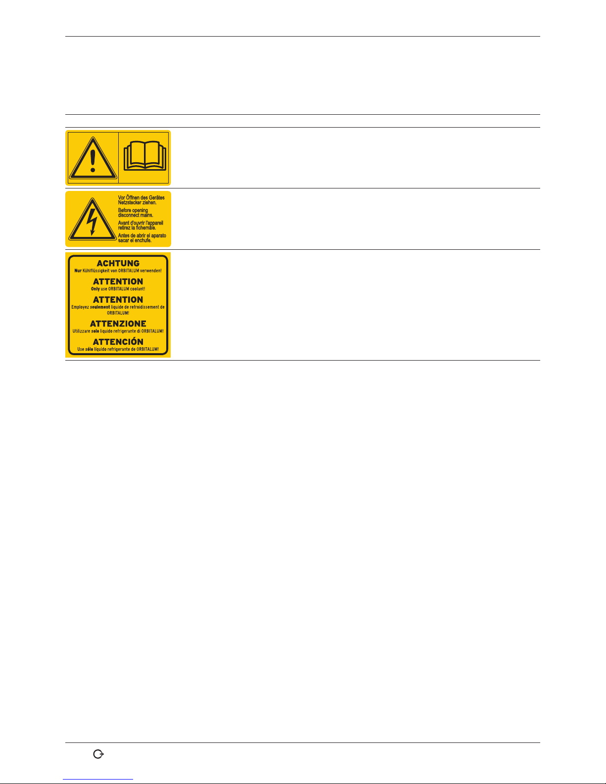
3.2.3 Operation via rotary knob
The rotary knob (Item 8) has either a fine or rough detent
when being turned, depending on whether you are
navigating between menu items/fields (rough detent) or
setting parameter values (for example weld current) (fine
detent).
Navigating to a menu item/field in the display:
X Turn the rotary knob.
The menu item/field appears in blue.
8
Page 15

ORBIMAT 180 SW | Operating instructions Description
(17.09.18) OW_ORBIMAT_180SW_BA_850060202_00_EN orbitalum tools Gmb H, D-78224 Singe n, www.orb italum.com, P hone +49 (0) 77 31 792-0 15
Select the menu item/field:
X Briefly press the rotary knob. The menu item is selected.
Exiting the menu and navigating to the next-higher menu level:
X Press the rotary knob long (> 2 seconds). The menu of the next-higher level appears in the display.
Setting a parameter/Entering a value:
X Highlight a field. The field appears in red.
X Change the value within the specified limit values: Turn the rotary knob.
X Saving the value and exiting the field: Briefly press the rotary knob.
3.2.4 Operation via an external keyboard
Navigating to a menu item/field in the display:
X Press the UP and DOWN arrow buttons.
Selecting the menu item/field:
X Press the ENTER key.
Setting a parameter/Entering a value:
X Highlight a field. The field appears in red.
X Entering a value: Change with the arrow buttons or enter directly with the number keys.
X Saving the value and exiting the field: Press the ENTER key.
Entering comments on procedures:
X Select a comment field.
X Enter the text using the keyboard.
Using push switches (softkeys) on the keyboard:
Function keys F1 through F6 on the external keyboard correspond to push switches 1 through 6.
Page 16
Description ORBIMAT 180 SW | Operating instructions
16
orbitalum tools GmbH, D-78224 Sing en, www.or bitalum.com, P hone +49 (0) 77 31 792-0 (17.09.18) OW_OR BIMAT_180SW_ BA_850 060202_00 _EN
3.3 Warning signs
The warning signs and safety signs located on the machine must be observed.
Image Position on machine Meaning Code
Hood inside Read the safety instructions! 871 001 057
Rear panel Before opening the unit disconnect the
mains plug.
850 060 025
Side, left Caution: Only use Orbitalum coolant! 884 001 001
Page 17
ORBIMAT 180 SW | Operating instructions Scope of application
(17.09.18) OW_ORBIMAT_180SW_BA_850060202_00_EN orbitalum tools Gmb H, D-78224 Sing en, www.or bitalum.com, P hone +49 (0) 77 31 792-0 17
4. SCOPE OF APPLICATION
The ORBIMAT 180 SW is characterized by the following scope of application and functions:
• For welding using the Tungsten Inert Gas (TIG) process
• Can be used for all materials that are fundamentally suitable for the TIG welding process.
• Simple and convenient operation thanks to multifunctional rotary knob or touch screen
• DC current welding source
• WIDE RANGE input voltages for safe operation of power sets or voltage networks with extreme fluctuations in voltage
• "Flow Force" function to reduce the gas pre-flow and post-flow time
• "Permanent gas" function
• Digital regulation of the weld gas quantity
• Monitoring of coolant and weld gas
• Control option for cold wire feed
• Possibility of connecting an external remote control
• Constant or pulsed wire feed motion and rotation
• Optimal visibility and operating conditions thanks to clearly laid-out 12.4" swivel monitor
• Graphically-supported operating interface and multilingual menu navigation via color display
• Metric and imperial measuring units
• Process-oriented, stable and real-time operating system without power-down sequence
• Automatic weld head recognition and resulting parameter modification
• Motor current monitoring of the drive motors
• Capacity to store over 5.000 welding procedures, providing systematic and clear procedure management thanks to
the creation of folder structures
• Welding data logging and printout of actual values
• Integrated system printer
• Possibility of connecting a monitor or printer (through HMDI/USB/LAN)
• Optional PC software (OrbiProg CA) for welding procedure management and logging
• Integrated, folding carrying grips
• Option to program up to 99 sectors
• Power and motor slope adjustment between the individual sectors
• Integrated liquid cooling system for cooling the connected weld heads
• Can only be used in combination with separately available liquid cooling system
4.1 Accessories
Optionally available:
WARNING!
Danger presented by using accessories that have not been approved.
Various injuries and damage to property.
X Use only original tools, spare parts, materials, and accessories from Orbitalum Tools.
4.1.1 ORBICAR W trolley
Thanks to its integrated liquid cooling function the ORBICAR W trolley
is the perfect supplement to the ORBIMAT 180 SW power source.
Beside the liquid cooling, the trolley is equipped with a practical holder for gas
bottles.
4.1.2 ORBICOOL Active
Very efficient compressor cooling device.
Particularly suitable for welding units in series production.
Page 18
Scope of application ORBIMAT 180 SW | Operating instructions
18
orbitalum tools GmbH, D-78224 Sing en, www.or bitalum.com, P hone +49 (0) 77 31 792-0 (17.0 9.18) OW_OR BIMAT_180SW_ BA_850 060202_00_ EN
4.1.3 ORBITWIN switching unit
To increase productivity, the ORBITWIN switching unit is available which allows the
alternately operation with 2 weld heads on the ORBIMAT.
4.1.4 ORBmax oxygen meter
For optical oxygen measurement using fluorescence extinction.
The ORBmax does not require any heating-up time. It recognizes the oxygen percentage reliably, rapidly and precisely during the entire welding process.
4.1.5 Remote control with cable
For transferring all the commands important for welding to the power source.
It is not required when working with enclosed orbital weld heads.
4.1.6 OCL-30 coolant
1 canister already included in the scope of delivery of the ORBIMAT 180 SW power
source.
Anti-freeze pre-mix for ORBIMAT power sources and cooling units to avoid freezing of
the cooling water. Protects up to –30 °C (-22°F) outside temperature. Increased service life of components of the cooling system through very high corrosion protection
and high pH-value. Excellent ignition characteristics due to low conductivity. Clear
cooling liquid.
4.1.7 ORBIPURGE forming set
For rapid and efficient internal forming during pipe and molded part weld connections
while at the same time reducing gas consumptions.
4.1.8 Paper rolls and ribbon cartridges
For internal system printer.
Suitable for all ORBIMAT orbital welding power supplies.
Page 19

ORBIMAT 180 SW | Operating instructions Technical specifications
(17.09.18) OW_ORBIMAT_180SW_BA_850060202_00_EN orbitalum tools GmbH , D-78224 Singen , www.orbit alum.com, Pho ne +49 (0) 77 31 792-0 19
5. TECHNICAL SPECIFICATIONS
PARAMETER UNIT ORBIMAT 180 SW REMARKS
Code 850 000 001
Weld system type Welding rectifier (inverter)
Input (mains)
Mains system 1 phase + PE
Mains input voltage [V (AV)] 110 - 230
Permissible voltage tolerance [%] +/–10
Mains frequency [Hz] 50/60 –
Continuous input current [A (AC)] 15.3
Continuous input [kVA] 3.6
Current consumption, max. [A (AC)] 19.5
Connection value, max. [kVA] 13.5
Power factor [cos ϕ] 1.0 (with 180 A)
Output (welding circuit)
Setting range weld current [A (DC)] 3 - 180 In 0.1 A increments
Weld current reproducibility [%] +/– 0.5
Rated current at 100% duty cycle [A (DC)] 160
Rated current at 60% duty cycle [A (DC)] 180
Weld voltage, min. [V (DC)] 10
Weld voltage, max. [V (DC)] 20
Open-circuit voltage, max. [V (DC)] 85
Ignition power, max. [Joule] 0.9
Ignition voltage, max. [kV] 10
Output (control)
Rotation motor voltage, max. [V (DC)] 24 PWM signal
Wire feeding motor voltage, max. [V (DC)] 24 PWM signal
Rotation motor current, max. [A (DC)] 1.5
Wire feeding motor current, max. [A (DC)] 1.5
Rotation tacho voltage [V (DC)] 0 - 10 Rotation speed, actual value
Other
Degree of protection IP 23 S
Cooling type AF
Insulation class F
Dimensions (wxdxh) [mm]
[inch]
600 x 400 x 310
23.6 x 15.7 x 12.2
300 CA without cooling unit
Weight [kg]
[lbs]
24.6
54.23
Gas input pressure [bar] 3 - 10 Via pressure reducer
Recommended gas input pressure [bar] 4 Via pressure reducer
Coolant volume [l] 2.2
Coolant pressure, max.
[bar] 4
Sound level, max. [dB (A)] 70
Page 20
Storage and transpor t ORBIMAT 180 SW | Operating instructions
20
orbitalum tools GmbH, D-78224 Sing en, www.or bitalum.com, P hone +49 (0) 77 31 792-0 (17.09.18) OW_ ORBIMAT_180S W_BA_ 850060202_ 00_EN
6. STORAGE AND TRANSPORT
6.1 Gross weight
ARTICLE WEIGHT*
ORBIMAT 180 SW [kg] 28.0
[lbs] 61.73
* incl. transpor t packaging
WARNING!
Damage of electronic components with personal harm and damage to property.
If coolant is still located in the machine during transportation, coolant can enter from the tank into
the machine interior if tilted strongly.
X Pump out coolant before transporting.
WARNING!
Danger of injury through high weight of the orbital welding power supply!
The orbital welding power supply has a weight of 28.0 kg (61.73 lbs).
X Always lift the orbital weld head with two persons or use a suitable means of transport.
X When lifting the machine do not exceed the permissible total weight of 25 kg for men and 15 kg
for women.
6.2 Preparing storage
Carry out the following steps before storage:
6.2.1 Removing the weld head from the orbital welding power supply
For procedure see operating instructions of weld head.
6.2.2 Pumping out coolant
1. Connect the drain hose to the coolant connection,
blue.
2. Hold the end of the drain hose into a collecting vessel
(min. 3 liter).
1
Page 21
ORBIMAT 180 SW | Operating instructions Storage and transport
(17.09.18) OW_ORBIMAT_180SW_BA_850060202_00_EN orbitalum tools GmbH , D-78224 Singen , www.orbit alum.com, Pho ne +49 (0) 77 31 792-0 21
Carry out the following steps in the menu of the welding power supply:
To protect the pump against possible dry running, the
software stops pumping out after approx. 30 seconds.
3. In the main menu, call up the "System settings" menu
item by turning the rotary knob.
4. Briefly press the rotary knob.
The "System settings" sub-menu appears.
Fig. 1: Main menu (long form)
5. Navigate to the "Service" menu item.
6. Briefly press the rotary knob.
The desired selection appears.
Fig. 2: Sub-menu – System settings
7. Select the "Coolant pump on" menu item.
8. Briefly press the rotary knob.
The "Pumping coolant out" message appears.
The "Cancel" button is highlighted in blue.
Fig. 3: Sub-menu – Service
Page 22
Storage and transpor t ORBIMAT 180 SW | Operating instructions
22
orbitalum tools GmbH, D-78224 Sing en, www.or bitalum.com, P hone +49 (0) 77 31 792-0 (17.09.18) OW _ORBIMAT_180 SW_BA_ 850060202_ 00_EN
9. Confirm "Cancel" by briefly pressing the rotary knob.
The coolant pump is switched off.
10. Check the fill level indication and abort the process
when the tank is empty.
NOTE! When the pump runs dry, this is accompa-
nied by an audible increase in speed.
X Abort the process immediately.
Fig. 4: Coolant – Pumping out
If the coolant does not exit the hose within a maximum of 10 seconds:
11. Stop drainage, as prolonged dry running can damage the pump.
12. Check the coolant level.
13. Check whether the pump is started and a pumping sound can be heard.
Page 23

ORBIMAT 180 SW | Operating instructions Commissioning
(17.09.18) OW_ORBIMAT_180SW_BA_850060202_00_EN orbitalum tools GmbH , D-78224 Singen, w ww.orbit alum.com, Phon e +49 (0) 77 31 792-0 23
7. COMMISSIONING
7.1 Scope of delivery
SCOPE OF DELIVERY CODE QUANTITY UNIT
ORBIMAT 180 SW Welding Power Supply 850 000 001 1 Pc.
Hose connection set ORBIMAT 875 030 018 1 Pc.
Dummy plug for remote control socket 875 050 006 1 Pc.
3.5 liter coolant OCL-3018 850 030 010 1 Bottle
Operating instructions with calibration certificate 850 060 201 1 Set
QuickStart guide 850 060 020 1 Pc.
Subject to modifications.
7.2 Checking the scope of delivery
X Check delivery for completeness and damage caused by transport.
X Report any missing parts or damage caused by transport to your supplier immediately.
7.3 Accessories (optionally available)
• ORBICAR W carriage with integrated liquid cooling
• ORBICOOL Active compressor cooling unit
• ORBITWIN Switching Unit
• Remote control with cable
• ORBmax residual oxygen meter
• Double pressure reducer
• TIG manual welding torch for ORBIMAT
Page 24
Commissioning ORBIMAT 180 SW | Operating instructions
24
orbitalum tools GmbH, D-78224 Sing en, www.or bitalum.com, P hone +49 (0) 77 31 792-0 (17.09.18) OW _ORBIMAT_180 SW_BA _850060202_ 00_EN
7.4 Connecting the welding power supply
CAUTION!
Damage to the orbital welding power supply through the mains supply voltage being exceeded.
X Check whether the mains supply voltage corresponds to the specifications in chap. 5.
X Observe requirements for the power supply: RCCB 30 mA.
DANGER!
Faulty ignition in case of unmounted or incorrectly positioned weld head!
Electric shock, bodily injury and damage to property also at other devices.
X If the weld head is not ready for operation, switch the machine to the "Test" function.
DANGER!
Improper access to and opening of the ORBIMAT system.
Electric shock.
X Disconnect the system from the mains.
X Remove all the external devices connected to the system (weld heads, etc.).
X If the machine was in operation beforehand, allow it to cool down sufficiently.
X Allow only a professional electrician to access the electrical system.
[ Never connect an opened system to the mains network.
DANGER!
Liquid in the housing due to improper use and transport.
Electric shock.
[ Do not place liquids (beverages) on the system.
X Do not block ventilation slots.
X Check housing interior for moisture after transporting the machine and leave it open to air it out
if necessary.
WARNING!
Ultraviolet radiation from the arc while welding.
Damage to eyes and burning of skin.
X During operation, wear eye protection to EN 170 and skin-covering safety clothing.
X At closed weld heads ensure proper working order of the eye protection.
WARNING!
Hot leaking liquids and hot plug connections during heavy operation.
Danger of scalding.
X Heed the safety precautions of the technical supervisor/person in charge of safety.
CAUTION!
Hot surfaces of the weld head and weld points, including for a period of time after welding.
Danger of burns.
X Wear safety gloves.
7.4.1 Setting up machine
X First set up the system for connection in such a way that it is as accessible as possible from the front and rear.
X Ensure that the machine is disconnected from the mains network on all sides.
X Secure the machine against being switched on unintentionally.
X Place the machine on a stable, fixed and plane base.
7.4. 2 Connecting a gas bottle
DANGER!
Exceeding the maximum permissible operating pressure of the forming gas can result in lethal
injuries.
X A pressure reducer must be used.
1. Check the stability of the gas bottle. Secure the gas bottle against falling over.
2. Ensure that the union nut on the pressure reducer fits the thread on the valve of the gas bottle.
3. Mount the pressure reducer on the gas bottle.
4. Connect the gas distributor (there is no gas distributor if a double pressure reducer is used).
5. Screw both included gas hoses onto the gas distributor or the double pressure reducer respectively..
6. Insert the gas hose (which is intended for connection to the power source and is identified by the plug-in nipple
made of brass on the end) into the provided connection socket on the rear back of the power source.
7. Connect the weld head.
Page 25

ORBIMAT 180 SW | Operating instructions Commissioning
(17.09.18) OW_ORBIMAT_180SW_BA_850060202_00_EN orbitalum tools GmbH , D-78224 Singen , www.orbi talum.com, Pho ne +49 (0) 77 31 792-0 25
7.4. 3 Connecting weld heads
For procedure see operating instructions of weld head.
7.4.4 Detaching coolant hoses
X Lightly push back the front ring on the machine-side connection and pull off the coolant hose.
7.4.5 Pumping out coolant
The connections of the machine close automatically when the coolant hose is removed.
X When connecting the coolant hoses, pay attention to the flow and return lines.
1. Connect the drain hose to the coolant connection, blue.
2. Close off the coolant hoses with the included plugs to prevent the coolant from running out of the weld head.
7.4.6 Closing off gas hose
X Actuate the side pawl on the hose-side plug connection and pull gas hose out of connection.
7.5 Commissioning
DANGER!
Faulty ignition in case of unmounted or incorrectly positioned weld head.
Electric shock, bodily injury and damage to property also at other devices.
X If the weld head is not ready for operation, switch the machine to the "Test" function.
DANGER!
Improper access to and opening of the ORBIMAT system.
Electric shock.
X Disconnect the system from the mains.
X Remove all the external devices connected to the system (weld heads, etc.).
X If the machine was in operation beforehand, allow it to cool down sufficiently.
X Allow only a professional electrician to access the electrical system.
[ Never connect an opened system to the mains network.
DANGER!
Liquid in the housing due to improper use and transport.
Electric shock.
[ Do not place liquids (beverages) on the system.
X Do not block ventilation slots.
X Check housing interior for moisture after transporting the machine and leave it open to air it out
if necessary.
WARNING!
Ultraviolet radiation from the arc while welding.
Damage to eyes and burning of skin.
X During operation, wear eye protection to EN 170 and skin-covering safety clothing.
X At closed weld heads ensure proper working order of the eye protection.
WARNING!
Hot leaking liquids and hot plug connections during heavy operation.
Danger of scalding.
X Heed the safety precautions of the technical supervisor/person in charge of safety.
CAUTION!
Hot surfaces of the weld head and weld points, including for a period of time after welding.
Danger of burns.
X Wear safety gloves.
Before welding is carried out the cooling circuit is filled with coolant.
Page 26

Commissioning ORBIMAT 180 SW | Operating instructions
26
orbitalum tools GmbH, D-78224 Sing en, www.or bitalum.com, P hone +49 (0) 77 31 792-0 (17.0 9.18) O W_ORBIMAT_18 0SW_BA _850060202 _00_EN
X Ensure that the machine is not connected to the mains network during filling.
X Secure the machine against being switched on unintentionally.
Please adhere to the following steps, otherwise the pump could be damaged by running dry:
7.5.1 Topping up coolant
1. Open the tank lid and fill ORBITALUM coolant OCL-30
(Code 850 030 010) carefully into the tank (2) until the
coolant level has reached the "MAX" marking on the
sight glass at the left-hand side panel of the power
source (3).
2
3
Use of other cooling units such as compressor cooling device, type ORBICOOL Active):
1. Fill in coolant in accordance with the operating instructions of the unit.
2. Connect the coolant hoses at the front connectors of the power source to ensure the coolant flow and temperature
monitoring by the power source.
7.5.2 Connecting Remote control/dummy plug
1. Connect the supplied dummy plug (4) or the optionally available remote control (5) (code 875 050 001) via the
adapter cable (6) (included in the scope of delivery of the remote control) to the remote control socket (7).
2. If a remote control is connected, the STOP button (8) must be unlocked as well.
3. The power source cannot be switched on without the dummy plug or unlocked remote control.
4
5
6
7
8
Page 27

ORBIMAT 180 SW | Operating instructions Commissioning
(17.09.18) OW_ORBIMAT_180SW_BA_850060202_00_EN orbitalum tools GmbH , D-78224 Singen , www.orbit alum.com, Pho ne +49 (0) 77 31 792-0 27
7.5.3 Switching on the power source
CAUTION!
X Observe requirements for the
power supply: RCCB 30 mA.
1. Connect the machine to the mains network.
2. The Off button (red) (9) lights up as soon as the machine is connected to the mains network.
3. Switch on the ORBIMAT at the green main switch (10).
The operating system is loaded and the main menu
appears in the display (11).
9
10
11
Problems while switching on
Does the machine not start the first time it is switched on?
X Check whether the pilot light in the main switch is lit up.
Is the pilot light not lit up?
There is a problem with the power supply (no voltage, plug not inserted).
X Check whether the power plug is properly inserted.
X Have the power supply checked.
Is the STOP indicator on the front panel lit up?
With external remote control connected: EMERGENCY-STOP switch is pressed.
1. Unlock EMERGENCY-STOP switch by turning it counterclockwise.
2. Switch off machine.
3. Wait at least 5 seconds and then switch machine on again.
Is an external remote control not connected?
The dummy plug is missing from the remote control connection, EMERGENCY-STOP is activated.
X Insert dummy plug to close the EMERGENCY-STOP circuit if necessary.
Page 28

Commissioning ORBIMAT 180 SW | Operating instructions
28
orbitalum tools GmbH, D-78224 Sing en, www.or bitalum.com, P hone +49 (0) 77 31 792-0 (17.09.18) OW_ ORBIMAT_180S W_BA_ 850060202_0 0_EN
7.5.4 Setting the language
The factory setting for the system language is "German".
Changing the language:
1. In the main menu call up the menu item "System
settings" by turning the rotary knob and confirm by
pressing.
2. Subsequently call up the menu item "Language".
3. Select the desired language and confirm with the
rotary knob.
Fig. 5: Setting the language
7.5.5 Setting the measuring units
The operating system can be set to "Metric" or "Imperial" measuring units.
The factory setting is "Metric".
Changing the measuring unit:
1. In the main menu call up the menu item "System
settings" by turning the rotary knob and confirm by
pressing.
2. Subsequently call up the menu item "System adjustments".
3. Use the rotary knob to select the desired measuring
unit under "Imperial sizes" by selecting "Yes/No" and
confirm.
Fig. 6: Setting the measuring unit
The ORBIMAT is now ready to operate.
Page 29

ORBIMAT 180 SW | Operating instructions Operation
(17.09.18) OW_ORBIMAT_180SW_BA_850060202_00_EN orbitalum tools GmbH , D-78224 Singen, w ww.orbit alum.com, Phon e +49 (0) 77 31 792-0 29
8. OPERATION
8.1 Auto programming
8.1.1 Setting parameters
1. Connect the weld head.
2. Switch on the machine.
The main menu appears in the display.
3. Select and highlight the "Auto programming" menu item.
The following display appears:
Field "....":
Return to main menu.
Fields "Weld head model" to "Wall thickness":
Parameter entry.
Field "Wire feed":
Welding with/without filler wire.
"Calculate program":
Calculation of the procedure with the entered parameters.
Fig. 7: Sub menu – Auto programming
8.1.2 Configuring weld head
1. Select the "Weld head" field and briefly press the rotary knob.
The following display appears:
A list of the weld heads which can be used with this system appears.
This system automatically detects the type of connected
head and offers it for selection first. In the example, this
is an OW 76S.
Fig. 8: Selecting a weld head
Page 30

Operation ORBIMAT 180 SW | Operating instructions
30
orbitalum tools GmbH, D-78224 Sing en, www.or bitalum.com, P hone +49 (0) 77 31 792-0 (17.09.18) OW_ ORBIMAT_180S W_BA_ 850060202_0 0_EN
2. Select the desired weld head by turning the rotary knob.
– or –
Select the weld head highlighted by the system.
3. Confirm by briefly pressing the rotary knob.
8.1.3 Configuring material
X Select the "Material" field and briefly press the rotary knob.
The following display appears:
Materials in the list:
• Carbon steel
• Stainless steel
• Titanium
Fig. 9: Selecting the material
1. Select the material.
2. Confirm by briefly pressing the rotary knob.
8.1.4 Configuring protective gas
1. Select the "Gas type" field and briefly press the rotary knob.
2. Select the protective gas.
3. Confirm by briefly pressing the rotary knob.
Page 31

ORBIMAT 180 SW | Operating instructions Operation
(17.09.18) OW_ORBIMAT_180SW_BA_850060202_00_EN orbitalum tools GmbH , D-78224 Singen , www.orbi talum.com, Pho ne +49 (0) 77 31 792-0 31
8.1.5 Configuring pipe diameter
1. Select the "Diameter" field.
The following display appears:
2. Select the value by pressing the rotary knob.
3. Enter values via the external keyboard or the rotary
knob.
The value range is automatically limited to the possible
diameter range of the connected or previously selected
weld head here.
Fig. 10: Pipe diameter setting
8.1.6 Configuring wall thickness
1. Select the "Wall thickness" field and briefly press the rotary knob.
The value range is limited to 4 mm (0.157").
We recommend a "tulip-shaped" or "U-shaped" preparation for wall thicknesses approx. 4 mm
(0.157") and larger, which might require carrying out your own weld tests. Auto programming can
be helpful here, because you can enter the thickness of the bluntly-joined root face (usually 1.5 - 2.5
mm/0.059" - 0.098") as the wall thickness first, and then manually improve the auto programmed
procedure calculated in this way.
2. Select the value by pressing the rotary knob.
3. Enter values via the external keyboard or the rotary knob.
8.1.7 Configuring wire feed
Selection is only possible if the connected weld head is capable of cold wire feeding.
If cold wire feeding is not possible, the option fields have a gray background, "No" is configured and this cannot be
changed by the operator (see also Fig. 10).
1. Select the "Wire feed" field and briefly press the rotary knob.
2. Select the "Yes" option (with wire feed) and "No" option (without wire feed).
8.1.8 Calculating procedure
X Select and briefly press the "Calculate procedure" menu item.
The procedure is calculated. The main menu appears in the display.
Page 32

Operation ORBIMAT 180 SW | Operating instructions
32
orbitalum tools GmbH, D-78224 Sing en, www.or bitalum.com, P hone +49 (0) 77 31 792-0 (17.0 9.18) O W_ORBIMAT_18 0SW_BA _850060202 _00_EN
8.2 Testing the procedure
8.2.1 Preparing weld head
These operating instructions can only provide basic information on the most commonly used weld heads (due to the
variety of tools which can be connected).
In the following, the important actions for so-called "open" weld tongs and cassette heads are listed.
X Refer to detailed information on preparing the operating instructions of the weld head.
D Gas bottle and weld head connected, see chap. 7.4, p. 24.
D Commissioning carried out, see chap. 7.5, p. 25.
D Machine switched on.
8.2.2 Preparing electrode
For almost all Orbitalum weld heads, electrodes with a diameter of 1.6 mm (0.063") and 2.4 mm (0.094") can be used.
X For "Micro head" type OW 12: Use only electrodes with a 1.0 mm (0.039") diameter.
X Up to a current of approx. 100 amperes (high-pulse): Use electrodes with a 1.6 mm (0.063") diameter (recommen-
dation).
X Calculate the electrode diameter based on the max. weld current of the application.
If lower currents are used, the use of 2.4 mm (0.094") electrodes can lead to a worsening of the
ignition characteristics and "wandering" of the arc at the electrode.
X Ensure good grinding of the electrode. Use an appropriate electrode grinding device. such as the ESG Plus tungsten
grinder (recommendation).
WARNING!
Sharply ground and pointy electrodes!
Danger of injury.
X Store ground electrodes so that there is no danger of injury.
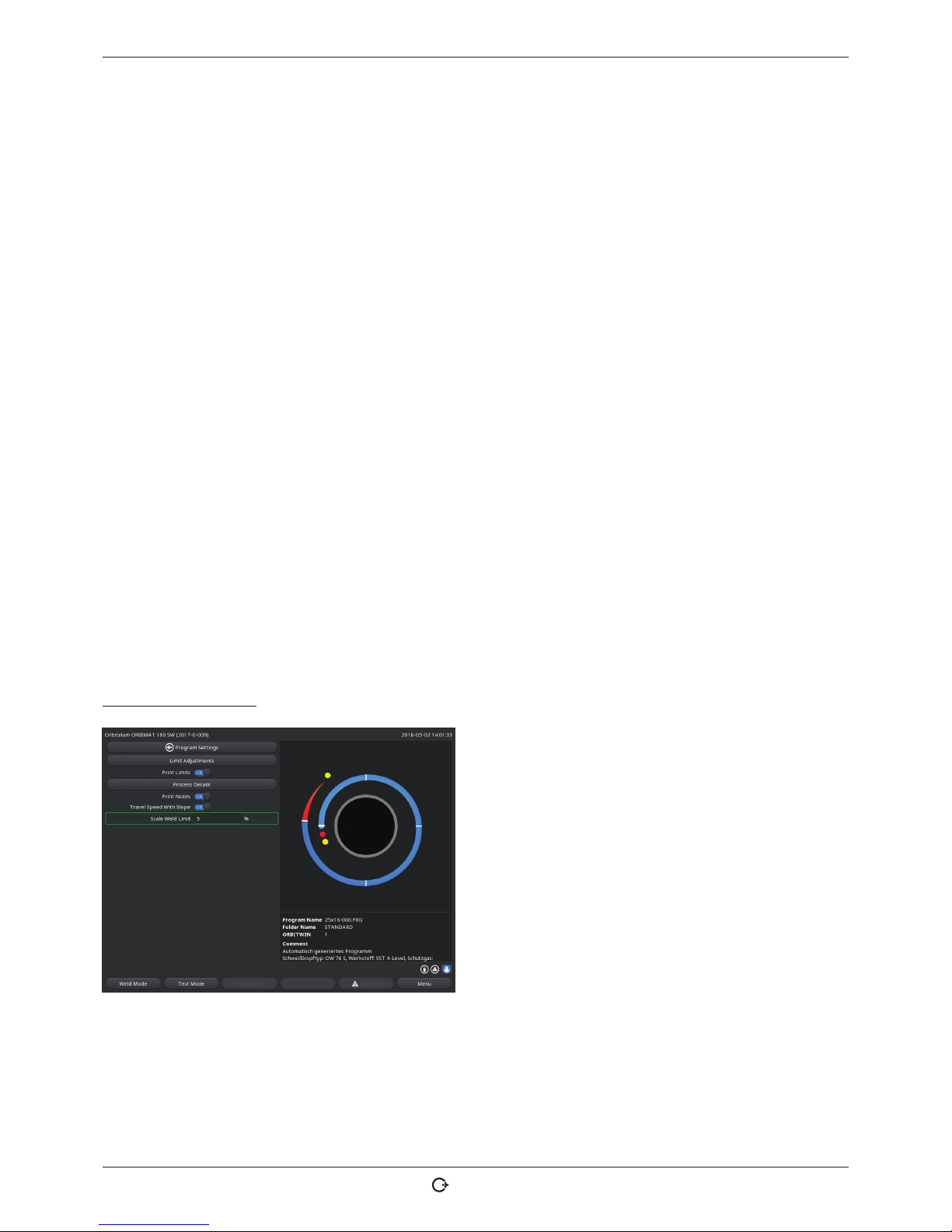
8.2.3 Turning weld head
You can turn the weld heads with a motor for insertion of the electrode.
CAUTION!
Clamping of fingers possible during manual moving.
X During clamping in move the rotor electrically in the opposite direction.
CAUTION!
Unintended starting of the welding procedure!
Danger of injury. Damage to materials and machine.
In the "ready to start" condition (see Fig. 11) the "Start" button could be pressed by an unauthorized person and start the welding procedure.
X Switch off the welding power supply for electrode replacement.
X After inserting the electrode ensure that the "Start" button in the display does not have a red
background.
X Only use the function for motor movement from the "red" start area if the weld head is being
moved immediately before starting the process, e.g. to change the starting position.
Page 33

ORBIMAT 180 SW | Operating instructions Operation
(17.09.18) OW_ORBIMAT_180SW_BA_850060202_00_EN orbitalum tools GmbH , D-78224 Singen , www.orbit alum.com, Pho ne +49 (0) 77 31 792-0 33
"Test mode" is indicated by the "Start" button having a yellow background.
The start command in test mode starts running a procedure without igniting an arc and therefore
without weld current; the gas valve and coolant pump are switched off. You can use this "dry run"
to check the change in level at the intended points on the pipe and the run of the motor.
Fig. 11: Machine ready to start – Welding (left) Fig. 12: Machine ready to start – Test run (right) – Start
X To change between the welding mode and the test mode the yellow "GAS" button at the weld head remote control
or at the handle of the weld head can be activated by pressing it and keeping it pressed for 3 seconds.
With the remote control of the weld head:
X Press the gray "Motor" button until the desired position is reached. Only one rotation direction is possible here.
With an additional remote control (optional, available as accessory):
X Press the "MOTOR+" or "MOTOR –" button.
The rotor turns in the selected direction as long as a button is being pressed.
With the push switches of the machine:
X Call up main menu, if necessary.
X Press softkey 2 "Test ".
The main menu in test mode appears in the display, and the "Start" button is yellow.
X Press softkey 4 "Motor".
The assignment of the softkeys for controlling the motor changes.
X Press "Motor forward" or "Motor backward" button.
The motor runs in the selected direction as long as the button is being pressed.
X Press softkey "Home".
The weld head turns to the open position.
X Press softkey "Motor OK" to exit the operating scheme.
X Press softkey 5 "Menu" to change directly to the main menu.
Page 34

Operation ORBIMAT 180 SW | Operating instructions
34
orbitalum tools GmbH, D-78224 Sing en, www.or bitalum.com, P hone +49 (0) 77 31 792-0 (17.09.18) OW_ORBIM AT_180SW_B A_85006 0202_00_E N
8.2.4 Connecting forming gas
With orbital welding, sufficient gas coverage must also be ensured inside the pipe ("root protection") with an inert gas
(usually argon). This also applies for the so-called "black" (ferritic) materials.
CAUTION!
X A pressure reducer must be used.
X Plug up lines of the gas bottle with suitable stoppers.
X Open the regulator on the gas bottle and set a low flow rate for the forming gas.
X Ensure sufficient gas pre purge time before starting the machine.
To determine the right time, the residual oxygen meter (ORB) can be used.
CAUTION!
Impermissible gas pressure inside the pipe. Penetration of melted metal into the weld head!
Damage to weld head.
X Ensure that gas pressure does not build up inside the pipe.
X When using closed weld heads, ensure that the same gas type is used both outside and inside
the pipe, i.e. the same gas both for the machine (weld head) and that which is fed into the pipe.
Different gas types can lead to an undefined mixture of both gases in the welding pocket and thus
to uneven weld penetration.
X Do not use "classic" forming gases with up to 30% hydrogen content.
A small amount of hydrogen which ends up in the welding pocket from inside the pipe via the pipe
joint can lead to considerably greater penetration, as the hydrogen releases additional energy during
combustion. Values gained from experience: An admixture of only 2% hydrogen has roughly the
same effect on penetration as a 10% increase in weld current.
8.2.5 Welding
Starting the welding process
X Before starting, read the section "Interrupting the welding process" (see chap. 8.2.6, p. 36) so that you can take
action immediately in case irregularities arise during a test run.
D Power source programmed
D Weld heads prepared for welding: properly connected and positioned
D Gas bottle secured and opened
D Machine switched on
D The main menu appears in the display.
X Press softkey 1 "Weld".
The machine is ready to start. The "Start " button in the display is red.
X Press softkey 1 "Start".
– or –
X Press the START button on an external remote control, if connected.
– or –
X Press the red START/STOP button on the weld head.
The coolant pump starts up, and the solenoid valve is opened. After the programmed gas pre-flow time passes, the arc is
ignited and the welding process begins.
Page 35

ORBIMAT 180 SW | Operating instructions Operation
(17.09.18) OW_ORBIMAT_180SW_BA_850060202_00_EN orbitalum tools Gmb H, D-78224 Singe n, www.orb italum.com, P hone +49 (0) 77 31 792-0 35
The machine carries out the welding process completely.
X Observe the welding process continuously and be prepared to take action at any time.
X With open weld tongs: Ensure proper guidance of the hose assembly while the rotor is circling.
Possible problems with the welding process:
• Incorrectly set weld current.
• LP weld tong not tensioned tightly enough.
• Forming gas quantity too high, holes being formed.
X In these cases, interrupt the welding process (see chap. 8.2.6, p. 36).
Welding process – Sequence
The machine carries out the welding process completely. During the welding process, the machine monitors the welding
process and the following parameters:
• Coolant flow rate: The welding process is stopped if the limit value of 0.8 l/min is undershot.
• Gas flow: The welding process is interrupted if approximately 3 l/min is undershot.
• The weld current, weld voltage and weld speed process parameters: Limit values specified in the procedure are
taken into account.
The following details appear in the display during the running welding process:
Process completion: Bar graph with specification of process completion (in %) for the respective current sector.
Correction factor: Percent value by which the current in
the current process was changed in comparison to the
saved procedure.
Parameters pipe diameter to wire LP speed: Display of
the process parameters of the procedure. The values can
be changed during the welding process. The changes
are saved by pressing the rotary knob (keyboard: ENTER)
to the current welding process. The changes are not yet
saved in the procedure. Fields with a gray background
cannot be edited.
Fig. 13: Display during running welding process
Graphic: Display of the weld sequence. After starting up, a pointer pointing to the inner yellow dot appears during gas
pre purge. After the gas pre purge, pool formation occurs (the time after ignition during which no rotational movements
are occurring for buildup of the weld pool). In the individual sectors, the respective current sector is highlighted in
white, and the accompanying red indicator indicates the current electrode position. The current sector number and current position (in angular degrees) appear in the bottom section of the graphic.
Info field: The following information appears in the info field (below the graphic): Name of the folder in which the procedure is saved, name of the running procedure, current measurement values for coolant flow (in l/min), coolant temperature and inverter temperature (in °C); gas flow, mean current, arc voltage.
Warning messages and error messages appear in the "Warning" field.
The info field only appears during a running welding process.
Other: The following information appears on the two bottom lines: Help texts for operation with the rotary knob. On
the right, information on the activated printer and the USB stick. When the printer is activated (for example log printing
after welding) or the storage medium is activated (procedure being loaded), the symbols are highlighted in blue.
Page 36

Operation ORBIMAT 180 SW | Operating instructions
36
orbitalum tools GmbH, D-78224 Sing en, www.or bitalum.com, P hone +49 (0) 77 31 792-0 (17.09.18) OW_ ORBIMAT_180S W_BA_ 850060202_0 0_EN
Softkeys: The current assignment of the softkeys appears at the bottom edge of the display. During the welding process, only softkeys 1 and 2 ("STOP" and "Final slope") are active.
Ending the welding process
If the process can no longer be controlled, shut down the system by using the main switch or pull
out the power plug!
The following steps are carried out automatically at the end of the welding process:
• Current is automatically sloped off to the programmed final current.
• The arc is extinguished.
• Gas flow and liquid cooling are deactivated after the programmed time expires.
• Machine switches to ready-to-start condition.
8.2.6 Interrupting the welding process
Switching off the entire system
X Switch off machine at the main switch.
– or –
X Press the EMERGENCY-STOP button on connected remote control.
The entire machine is disconnected from the mains network immediately and completely (both poles). No other functions
are carried out here: The gas flow is interrupted immediately. The current weld becomes unusable.
Stopping a running process
X Press softkey 1 ("STOP").
– or –
X Press the STOP button on the connected remote control.
– or –
X Press the red START/STOP button on the weld head.
The weld current is switched off immediately. The machine remains in operation, the gas post purge time runs and the
liquid cooling of the weld head is carried out until the end of the gas post purge time.
A slight crater can arise in the seam on the workpiece, and this can be compensated for by over-welding it.
Premature slope-off of a running process
X Press softkey 2 ("Final slope").
– or –
X Press the "Final" button on the weld head.
– or –
X Press the slope-off symbol on the connected remote control.
The machine slopes off the weld current as per the procedure. The weld head continues running during the slope-off
phase. After slope-off, the weld current is switched off, the gas post purge and pump continue running until the end of
the programmed time.
Page 37
ORBIMAT 180 SW | Operating instructions Operation
(17.09.18) OW_ORBIMAT_180SW_BA_850060202_00_EN orbitalum tools GmbH , D-78224 Singen , www.orbit alum.com, Pho ne +49 (0) 77 31 792-0 37
8.3 Adjusting the procedure
8.3.1 Reasons and steps for adjusting procedure
The auto programming of the machine cannot take all influencing factors into account during welding. Procedures can
be adjusted after the test run for this reason.
Possible reasons are:
• Batch-dependent fluctuations in the material composition.
• Different dissipations (pipe on solid parts) etc. For example due to components with different sizes.
X Improve the procedure step by step. When adjusting, change only one parameter at a time so that you can better
judge the influence on welding.
X Save the adjusted procedure.
X After the adjustment, carry out a test run of the parameters.
X Observe the effects of the adjustment and carry out further adjustments if necessary.
8.3.2 Making percental changes
Reason: Welding result even, but weld seam penetrated too lightly or too strongly.
The percentage change affects all levels (sectors) on high- and low-pulse current.
After the test run, the "Scale weld" field is highlighted in the display.
1. Highlight a field.
2. Adjust and save the value with the rotary knob or keyboard:
Positive value: Increase the weld current.
Negative value: Reduce the weld current.
The settable value range can be limited in the procedure (for example only max. +5% and min. –5%).
Changing the scale weld
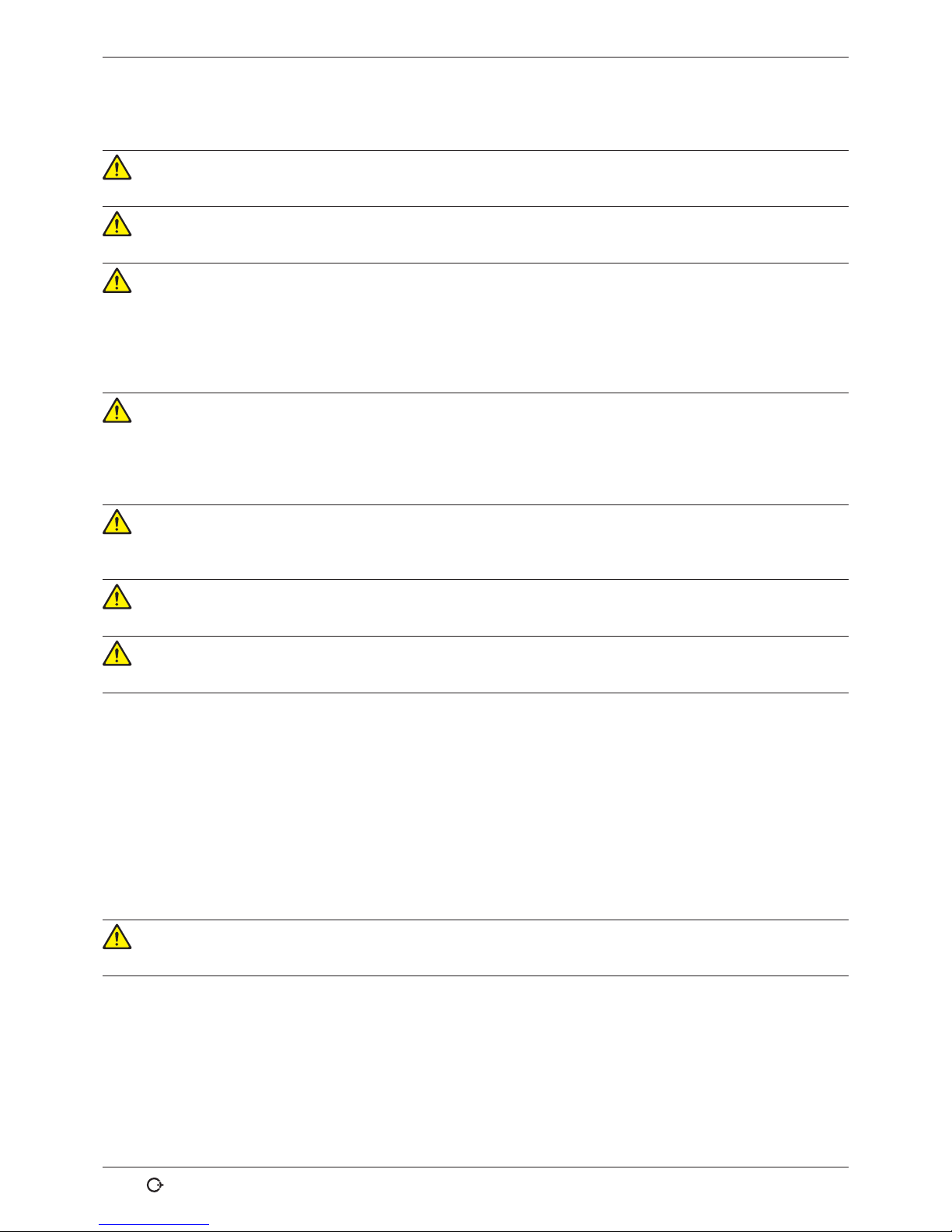
1. In the main menu, select "System settings" > "Program settings".
The current limit within which the operator can change
the scale weld in "completed" mode (production mode) is
specified in the "Scale weld limit" field.
Example: Specification "5%" – Change in range from –5%
to +5% (absolute range: 10%).
2. Adjust and save the value with rotary knob or keyboard.
Fig. 14: Scale weld limit
Page 38

Operation ORBIMAT 180 SW | Operating instructions
38
orbitalum tools GmbH, D-78224 Sing en, www.or bitalum.com, P hone +49 (0) 77 31 792-0 (17.09.18) OW_ORBIM AT_180SW_B A_85006 0202_00_E N
8.3.3 Adjusting individual parameters
Individual parameters are adjusted in the respective sectors.
1. Select softkey 1 "Weld" or softkey 2 "Test ".
2. Using the "go back..." or "go further..." button select, adjust and save the individual parameters.
3. Press softkey 1 ("Weld") or softkey 2 ("Test ").
– or –
1. Press softkey 5 ("Leave").
2. In the main menu, select "Manual/Adjust programming" > "Adjust parameters".
3. Select the desired sector.
4. Select, highlight, change and save parameters.
5. Press softkey 1 ("Weld") or softkey 2 ("Test ").
8.3.4 Digital gas management
Gas quantities can be programmed individually. Various possibilities of adjusting the gas pre purge time and gas post
purge time:
X The transmission of the weld head is to be kept permanently free of oxygen during idling. This allows the gas pre
purge time as well as the process time to be reduced.
8.3.5 Adjusting gas times
Auto programming generates gas pre and post purge times of 30 seconds for cassette weld heads. The adjustment of
the gas times (gas pre purge time and gas post purge time) may be necessary to optimize the results of the welding
process.
The space to be filled with gas also depends on the weld head size and pipe diameter. It may therefore be necessary to
shorten the gas pre purge time for smaller weld heads. If the seam (with closed weld heads) is bare and nearly free of
annealing colors right from the beginning, the gas pre purge time is correct. For special materials (e.g. titanium), it may
be necessary to lengthen the gas times. The gas post purge time must at least be long enough that the material no longer
reacts to oxygen in the air when the closed weld heads are opened. This also depends on the energy introduced during
welding.
Cassette weld heads: Due to electrode oxidation, do not use a gas post purge time of less than 10 seconds.
LP weld tongs: Do not change the gas times specified by auto programming.
1. Press softkey 1 "Weld".
2. Using the "go back to gas post purge time" or "go
further to gas pre purge time", select, adjust and save
the individual parameters.
– or –
1. In the main menu, select "Manual/Adjust programming" > "Adjust parameters".
2. Select, highlight, adjust and save parameters.
X Press softkey 1 ("Weld") or softkey 2 ("Test").
The machine is ready to start.
Fig. 15: Input field – Gas post purge time
Page 39

ORBIMAT 180 SW | Operating instructions Operation
(17.09.18) OW_ORBIMAT_180SW_BA_850060202_00_EN orbitalum tools GmbH , D-78224 Singen, w ww.orbit alum.com, Pho ne +49 (0) 77 31 792-0 39
8.3.6 Adjusting ignition current, final current and current slope-off
X Adjust the values specified by auto programming only in exceptional cases (for example with extremely thin-walled
pipes).
Ignition current: Value specified during ignition. The ignition current is active only very briefly and affects the ignition
behavior itself. If the ignited arc is detected, the machine switches to the current programmed on level 1 within a few
tenths of a second.
Final current: Current level reached by the final slope-off immediately before switch-off of the arc at the end of the
welding process. The value must be greater than 0. Otherwise, the arc will cut out before the end of the welding process.
X Ensure that the value (3 A) is not zero.
For extremely large arc gaps (LP tongs):
X If the arc cuts out at the end of current slope-off: Increase the value.
Slope-off time: Time from the end of the last-used weld sector to the switch-off of the arc. This is identified by an increasingly narrower weld seam on the welded part.
The current slope-off is necessary to prevent a final crater (formed due to immediate switch-off) from being formed.
Is a longer or shorter run-out of the weld seam desired?
X Increase or decrease the value.
1. Ignition current: Using the "go further to gas pre
purge time" > "go further to start delay time" " but-
tons, select, adjust and save parameters.
2. Final current and current slope-off: Using the " "go
further to gas post purge time" > "go back to weld seam
end" buttons, select, adjust and save parameters.
3. Press softkey 1 ("Weld") or softkey 2 ("Test ").
– or –
1. In the main menu, select "Manual/Adjust programming" > "Adjust parameters".
2. Select, highlight, adjust and save parameters.
3. Press softkey 1 ("Weld") or softkey 2 ("Test ").
The machine is ready to start.
Fig. 16: Input field – Ignition current and pool formation time
8.3.7 Adjusting the pool formation time
Pool formation time: Start delay of the rotation motor so that a point weld penetration already exists at the beginning
of the rotation movement. The pool formation time must be adjusted if the starting point shows too much or too little
weld penetration. Adjustment of the pool formation time is made easier by observing, for example, the root formation
inside the pipe on a test piece. Ideally, the rotation should begin immediately after a visible formation of the melt pool
inside the pipe.
Increasing the weld current in the 1st sector affects the energy introduced to the melt pool during pool formation.
X Ensure that the weld current of the 1st sector is already used during pool formation.
Page 40

Operation ORBIMAT 180 SW | Operating instructions
40
orbitalum tools GmbH, D-78224 Sing en, www.or bitalum.com, P hone +49 (0) 77 31 792-0 (17.09.18) OW_O RBIMAT_180S W_BA_ 850060202_0 0_EN
1. Using the "go further to gas pre purge time" > "go further to start delay time" " buttons, select, adjust and save param-
eters.
– or –
1. In the main menu, select "Manual/Adjust programming" > "Adjust parameters".
2. Select, highlight, adjust and save parameters.
3. Press softkey 1 ("Weld") or softkey 2 ("Test ").
The machine is ready to start.
8.3.8 Adjusting welding current and transition times ("Slope")
The weld currents in the individual sectors are the process parameters which are changed most often in practice to
achieve optimum and even weld seam formation. If the seam is welded unevenly or insufficiently, adjust the energy being applied.
To prevent changes in voltage from being sudden, and thus a possible visible change in the seam, a value can be specified for a transition time starting with sector 2. The value is a percentage value of the sector time in which a linear current transition from (current) value of the previous sector follows the current value of the current sector.
Example
• Current of 50 A (HP) in sector 1 and 45 A (HP) in sector 2
• Sector time in level 2 of 10 sec.
• Slope of 10%
Process sequence
• The sector is welded up to the end with 50 A (HP or LP as programmed).
• Within 10% of the sector time (meaning 10% of 10 sec = 1 sec), the current is reduced linearly from 50 A to 45 A.
• For the remaining sector time in sector 2 (= 9 sec), the current remains constant at 45 A.
Auto programming uses these linear transitions. This reduces the number of sectors. The effects to be compensated for
by a change in current (e.g. heating of the pipes during welding) do not have a sudden character and can be compensated for better using transitions.
Alternatively, it is also possible by adjusting the weld speed. With different weld speeds, however,
the seam appearance changes ("scaling") if the high- and low-pulse times are not adjusted in the
same proportion.
Recommendation for standard applications
X The method of a constant weld speed within a procedure "recommended" by auto programming is retained.
X To achieve an even seam with proper weld penetration, adjust the current setting in the individual sectors.
For minor adjustments:
X Change only the high-pulse current.
– or –
X Change both currents in the same direction to obtain the desired "pulse effect".
1. In the main menu, select "Manual/Adjust programming" > "Adjust parameters".
2. Select the desired sector.
The respective selected sector is highlighted in color to the right in the display. The angular degrees of this sector is
specified.
3. Select, highlight, adjust and save the "HP current", "LP current" and "Slope" parameters.
4. Press softkey 1 ("Weld") or softkey 2 ("Test").
Page 41

ORBIMAT 180 SW | Operating instructions Operation
(17.09.18) OW_ORBIMAT_180SW_BA_850060202_00_EN orbitalum tools Gmb H, D-78224 Sing en, www.orb italum.com, P hone +49 (0) 77 31 792-0 41
The machine is ready to start.
The specification of the current transition in percent can be problematic under certain circumstances
if procedures from other machines must be transferred with an incompatible data format and these
machines are programmed with a slope in seconds instead of percent.
The field for input of the slope time can be switched from percent to seconds, see also "Special keyboard commands" (chap. 8.17, p. 63).
X To switch the slope time specification from % to sec (and vice versa), press the "S", "L" and "O"
keys (for SLOPE) on the virtual keyboard.
X Confirm the message (see Fig. 17) by pressing the rotary knob.
The next time the machine is started, the % values corresponding to the seconds appear.
Fig. 17: Converting the slope time from percent to seconds
8.3.9 Adjusting pulse times
Pulse times in most application cases: 0.05 to 0.5 seconds.
Auto programming calculates the pulse times from the wall thickness. Adjusting the pulse times affects the seam appearance: A shorter pulse time yields a finer scale.
1. In the main menu, select "Manual/Adjust programming" > "Adjust parameters".
2. Select the desired sector.
The respective selected sector is highlighted in color to the
right in the display. The angular degrees of this sector is
specified. An image of the seam scale appears below the
process graphic.
3. Select, highlight, adjust and save the "HP time" and
"LP time" parameters.
4. Press softkey 1 ("Weld") or softkey 2 ("Test").
The machine is ready to start.
Fig. 18: Input field of a sector with representation of the seam scale
X Press softkey 4 "Apply value" to apply all the parameters such as amount of electricity, pulse times or speeds in all
the subsequent sectors.
Page 42

Operation ORBIMAT 180 SW | Operating instructions
42
orbitalum tools GmbH, D-78224 Sing en, www.or bitalum.com, P hone +49 (0) 77 31 792-0 (17.0 9.18) O W_ORBIMAT_18 0SW_BA _850060202 _00_EN
Recommendation
[ Do not set the high- and low-pulse times with different values.
Experienced users can adjust the pulse times with different values. This is recommended for certain materials (such as
copper).
8.3.10 Adjusting weld speed and transition time ("Slope")
Auto programming specifies weld speeds in the range of 70 – 100 mm/min (at pipe circumference) that lie in the medium range for the TIG process. As of a certain wall thickness, the system drives the motor in sync with the pulse: The
motor remains nearly still during the high-pulse phase and moves only during the low-pulse phase.
This method reduces the volume of the liquid material so that the melt pool remains under control even with wall thicknesses
of around 4.0 mm (0.157"). In these cases, the average value of both speeds is to be calculated for the resulting speed if the
high- and low-pulse times are the same length.
In principle, a high weld speed (up to a maximum of approx. 200 mm/min makes sense) is only possible if the process
does not have tolerances (offset, wall thickness, air gap, etc.).
At a somewhat <lower speed, irregularities (such as minor fluctuations in the pipe wall thicknesses) are tolerated by the
process. For auto programming middle values are therefore provided.
If a higher weld speed is required for an application:
X Increase the current to introduce the same energy (per section) into the process again.
For different weld speeds in the sectors:
When switching between sectors at different speeds, the motor is accelerated or braked linearly if a slope time has
been set.
Deactivating transition in the speed
1. In the main menu, select "System settings" > "Program settings".
2. Select the "No" option for "Speed without ramp".
The slope is deactivated in the current procedure.
3. Press softkey 5 ("Menu").
The machine is ready to start.
If you are working with different speeds at high- and low-pulse current:
X Do not select pulse times shorter than 0.2 seconds to balance the inertia of the motors and the
machinery.
If the motor is to nearly stand still in the high-pulse phase:
X Enter value "1" for the speed.
The motor continues to run and does not have to overcome static friction when starting up. This
protects the motor and leads to higher precision while observing the angle of rotation while welding.
Auto programming automatically generates the value 1 for the weld speed in the high-pulse time
during operation in sync with the pulse.
Page 43

ORBIMAT 180 SW | Operating instructions Operation
(17.09.18) OW_ORBIMAT_180SW_BA_850060202_00_EN orbitalum tools GmbH , D-78224 Singen , www.orbi talum.com, Phone +49 (0) 77 31 792- 0 43
Adjusting wire feed parameters
X Only adjust wire feed parameters if a weld head is connected or was selected with cold wire supply.
With other weld heads, the input fields are grayed-out.
Wire feed parameters:
• Wire start delay (in seconds)
• Wire final delay time (in seconds)
• Wire retract (in seconds)
• Wire HP speed (in mm/min)
• Wire LP speed (in mm/min)
Changing the wire feed quantity requires a change to the current, since more (cold) material is introduced to the welding process with an increased wire speed, for example. If the wire quantity is too high, it is difficult to control the melt
pool in the individual positions or it breaks away or drips off.
Wire start delay: The time from ignition of the arc to the introduction of the wire feed. The time corresponds with the
time for pool formation (start delay for the rotation motor). It cannot be longer than the pool formation time.
In special cases, it can be shorter than the bath formation time, so that the wire enters the melt pool while the rotation
motor is still not moving.
X Do not set wire start delay too short, as the wire is not "taken up" if the melt pool has not yet been formed.
Wire final delay time: Time during which the wire is still fed to the process during current slope-off at the end of welding. Its minimum value is 0 and maximum value is as long as the current slope-off. With a value of 0, the wire feed stops
when the current slope-off begins. If the time corresponds to the duration of the current slope-off, wire continues to be
fed during the entire slope-off time.
Since the introduced energy declines as the current slopes off, the wire feed should stop when there is no longer a melt
pool.
Wire retract: Time during which the wire running direction is reversed at the end of the wire feed so that the wire
does not rest on the pipe when turning back the weld head. The retraction time should be approx. 1 - 2 sec. and is set
properly when the wire extends 2 - 3 mm from the feed tube after retraction. If the time is too long, the wire is pulled in
completely and the end (which is usually still a liquid ball) can adhere to the wire feed tube.
Wire HP/LP speed: The wire feed speeds of the filler wire (in mm/min) in the individual sectors. Auto programming usually
controls the wire in sync with the pulse: The wire feed motor does not move on the low pulse, as the energy of the arc
may not be sufficient to melt the wire under certain circumstances here.
To achieve a higher deposition rate:
X Increase the speed of the wire in the high-pulse phase.
– or –
X Feed wire in the low-pulse phase as well. The weld current set for low pulse must be sufficient here.
1. In the main menu, select "Manual/Adjust programming" > "Adjust parameters" > "Pool formation".
2. Consecutively select, highlight, adjust and save the "Wire start delay", "Wire final delay time" and "Wire retract"
parameters.
3. Select "go forward to sector 1" or select the desired sector.
The respective selected sector is highlighted in color to the right in the display. The angular degrees of this sector is
specified. An image of the seam scale appears below the process graphic.
4. Select, highlight, adjust and save the "Wire HP speed" and "Wire LP speed" parameters.
5. Press softkey 1 ("Weld") or softkey 2 ("Test ").
Page 44

Operation ORBIMAT 180 SW | Operating instructions
44
orbitalum tools GmbH, D-78224 Sing en, www.or bitalum.com, P hone +49 (0) 77 31 792-0 (17.09.18) OW_ORBIM AT_180SW_BA _8500602 02_00_EN
The machine is ready to start.
8.3.11 Changing the sector
Auto programming divides welding into different sectors (usually 4 to 6). The parameters can be programmed for each
sector.
The sector borders can be shifted manually, and sectors can be added or deleted.
Adjusting sector borders with the rotary knob
1. In the main menu, select "Manual/Adjust programming" > "Divide into levels".
The sector list appears on the left in the display (five sectors in the example, see Fig. 19). The process sequence appears on the right.
2. Turn rotary knob until the pointer points to a white
sector border.
The green pointer moves through the sector, and the
degree information of the position appears at the bottom
edge of the process representation.
3. Ensure that the pointer is positioned correctly. For
this purpose, compare value in the sector list (end
sector 1 = 90°) with the degree information.
4. Briefly press the rotary knob.
The sector border is displayed in green.
Fig. 19: Sector list – Pointer position for 90°
5. Move sector border to the desired position with the rotary knob.
6. Briefly press the rotary knob.
7. Rapid jumping to the sector borders by pressing and immediately turning the rotary knob.
The sector border is saved at the new position. The sector list is updated accordingly.
Adjusting sector borders with the keyboard
1. In the main menu, select "Manual/Adjust programming" > "Adjust parameters".
2. Select the desired sector, e.g. "Sector 1".
3. Select and highlight the "Final angle" field, enter a value and save it.
To adjust further sectors:
4. Select "go forward to sector ..." or "go backward to sector …".
Moving/deleting sectors
Example: Divide sector 1 (0 - 90°) into two sectors. New border at 45°.
1. In the main menu, select "Manual/Adjust programming" > "Divide into levels".
Page 45

ORBIMAT 180 SW | Operating instructions Operation
(17.09.18) OW_ORBIMAT_180SW_BA_850060202_00_EN orbitalum tools Gmb H, D-78224 Singe n, www.orb italum.com, Phone +49 (0) 77 31 79 2-0 45
The sector list appears on the left in the display (five sectors in the example, see Fig. 19). The process sequence appears on the right.
2. Move the pointer to the 45° position with the rotary knob.
3. Briefly press the rotary knob.
The new sector border is set, and the sector list is updated. The new sector appears in the list.
The parameters of the new sector are copied from the previous sector.
4. Adjust parameters of the new sector.
Example: Delete sector 1
1. In the main menu, select "Manual/Adjust programming" > "Divide into levels".
The sector list appears on the left in the display (five sectors in the example, see Fig. 19). The process sequence appears on the right.
2. Move the pointer to the 90° position with the rotary knob.
3. Ensure that the pointer is positioned correctly. For this purpose, compare value in the sector list (end sector 1 =
90°) with the degree information.
4. Briefly press the rotary knob.
5. Move the pointer to the next-lowest border to the left (0°) with the rotary knob.
6. Briefly press the rotary knob.
Sectors 1 (0 - 90°) and 2 (90 - 185°) are combined to form a new sector 1 (0 - 185°). Sector 1 and the parameters of this
sector are deleted. The new sector has the parameters of the old sector 2.
7. Check parameters of the sector.
Note: Moving the sector border to the right (185°) causes the new sector 1 to accept the parameters of the old sector 1.
Page 46

Operation ORBIMAT 180 SW | Operating instructions
46
orbitalum tools GmbH, D-78224 Sing en, www.or bitalum.com, P hone +49 (0) 77 31 792-0 (17.09.18) OW_O RBIMAT_180S W_BA_ 850060202_0 0_EN
8.4 Saving and calling up a procedure
8.4.1 Saving a procedure
Procedure status
With an unsaved procedure, "[unsaved]".appears next to the name of the procedure in the "Procedure name" field in the
display. The procedures are saved in folders. The folders can be created and named as desired. The "Default" folder is
specified and cannot be deleted.
X Recommendation: Save procedures regularly, including after adjusting individual parameters.
Deactivating the folder structure
1. In the main menu, select "System settings" > "System adjustments".
2. Select the "No" option for "Create new folders".
The folder structure is deactivated. All procedures are saved in the main directory.
Saving a procedure under an existing name
The name of the folder in which the procedure is saved appears in the "Folder" field in the display.
1. Press softkey 3 ("Save").
A prompt appears.
2. Confirm the prompt with "Yes".
3. The procedure is saved with the adjustments.
Saving an adjusted procedure under a new name
1. Press the "Save" button in the main menu.
2. Press "New folder" button or select an existing folder.
If "New folder" was pressed:
3. Select the input field and briefly press the rotary knob.
4. The input field is activated.
5. Enter the folder name with the keyboard.
6. Press the OK" button.
The new folder is created.
7. Select the new folder.
8. Highlight and activate the input field for procedure names and enter the new procedure name.
9. Press the OK" button.
The procedure is saved with the new name (possibly in newly created folder).
8.4.2 Calling up a procedure
X Recommendation: Save unsaved procedures if necessary before calling up a procedure.
1. Press the "Select procedure" button in the main menu.
2. Select the folder.
A list of procedures is displayed. Additional information on each procedure appears in the display.
Page 47

ORBIMAT 180 SW | Operating instructions Operation
(17.09.18) OW_ORBIMAT_180SW_BA_850060202_00_EN orbitalum tools GmbH , D-78224 Singe n, www.orbi talum.com, Ph one +49 (0) 77 31 792-0 47
3. Select the procedure.
If an unsaved procedure is loaded in the RAM, another procedure cannot be loaded. A warning is
displayed:
"Cancel": The procedure call is cancelled. The main menu appears.
"No": The unsaved procedure is not saved, and any adjustments made are lost. The selected procedure is called up.
"Yes": The unsaved procedure is saved. The main menu appears.
If unsaved procedures are saved or adjustments were rejected:
4. Call up the procedure again.
The selected program appears in the display.
8.5 Locking machine with a login
The machine disposes of two views of the main menu:
Long form
Procedure programming mode. Procedures can be changed, and sensors and monitoring functions can be activated/deactivated.
Short form
Production mode. All functions which lead to changes in the existing procedures cannot be executed in the "Short menu"
and are not displayed. Sensors and monitoring functions cannot be deactivated.
The saved data are largely protected against loss or
change.
Recommendation
X Create backup copies of the data of the internal
memory at regular intervals.
Fig. 20: Main menu (Short form)
1. Touch the login icon at the bottom right in the screen.
A virtual keyboard is displayed.
2. Enter the password and confirm by pressing the rotary knob.
X Login icon highlighted in blue = Logged in.
3. To log out touch the login icon at the bottom right in the screen.
X Icon highlighted in blue becomes gray = Logged out.
Page 48

Operation ORBIMAT 180 SW | Operating instructions
48
orbitalum tools GmbH, D-78224 Sing en, www.or bitalum.com, P hone +49 (0) 77 31 792-0 (17.09.18) OW_ORBIM AT_180SW_BA _8500602 02_00_EN
Initial password at the initial login: 12345
The password can be changed at any time under the menu item "System settings".
If the password is lost/forgotten, please use the machine-specific master password specified in the
calibration certificate. If logging in with the master password is not possible, please contact Orbitalum.
Limitation of the percentage current change
In the "disabled" position, the operator can not adjust or delete existing procedure sequences.
If it is necessary, however, to make small adjustments for a welding task (e.g. due to batch-based fluctuations of the
material composition or minor changes in the wall thickness), a percentage limit can be set in the welding procedure.
The operator can adjust the current within this limit.
This adjustment is not saved in the procedure and affects all sectors and the high-pulse and low-pulse current.
X Recommendation: Allow for maximum 10% (20% adjustment range).
Specifying "5%" means that it is possible to adjust up to 5% above or below the base value. The total adjustment range
amounts to 10%.
Specifying a limit
1. Locking the machine with a login
The main menu "Long form" appears in the display.
2. In the main menu, select "System settings" > "Program settings".
3. Select and highlight the "Scale weld limit" field and enter a percentage value.
– or –
If no adjustment is desired: Enter the value "0".
4. Save the procedure.
5. Lock the machine with a login.
8.6 Tacking function
1. Select the basic adjustments.
2. Use the rotary knob to select the "Advanced" option and confirm by pressing.
3. Select the "On" option for "Tacking".
The following four fields are activated:
4. Accept or adjust the suggested parameters.
5. Test the tacking function: Carry out welding on a test pipe.
6. Interrupt the test weld with "STOP" after the tacking phase.
7. Remove the test pipe from the weld head and assess the tacking.
8. Adjust the parameters manually if necessary.
Tack points
Number of tack points on the pipe. The system calculates the optimum position of the points from the specified number
of points and moves to them during the tacking procedure: With four tack points, the two opposite tack points (0° and
180°) come first, followed by the other points (90° and 270°).
Tack current
Presetting: High-pulse current from level 1.
During the tacking procedure, this current is switched on after the position for the respective tack point (with rotor not
moving) is reached. If the time specified under "Tack time" has past, the system switches to a low current (the "Pilot
current ") and moves to the next tack point at the maximum possible speed.
Page 49
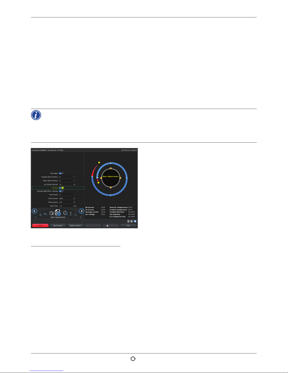
ORBIMAT 180 SW | Operating instructions Operation
(17.09.18) OW_ORBIMAT_180SW_BA_850060202_00_EN orbitalum tools GmbH , D-78224 Singen , www.orbi talum.com, Pho ne +49 (0) 77 31 792-0 49
X In case of weak tacking: Lengthen the tack time or increase the tack current.
Pilot current
Current upon arriving at tack points. The pilot current should, on the one hand, be high enough so that the arc does not
cut out, and on the other hand low enough so that a melt pool does not form on the pipe surface.
[ Recommendation: Do not change the pilot current.
Tack time
Duration for the readiness of the tack current when the position is reached and the rotor is not moving.
X In case of weak tacking: Lengthen the tack time or increase the tack current.
When a tacking procedure is carried out first, the starting point of the welding is moved.
X Compensate for this shift by entering an angle in the "Start position" field (see Fig. 7.4).
The angle specified for "Start position" is approached by the system before welding begins. By selecting this angle accordingly, the starting point of welding is moved back to the original position.
X Recommendation: Run the procedure in test mode and check the movement of the rotor when
doing so.
Fig. 21: Tacking function
Selection field "Weld After Tacking" (optional)
Select this option to prefasten the workpieces in order to avoid any possible material distortion during the welding
process.
At an activated function the welding process starts automatically after the tacking process.
8.7 Using the second gas pressure level ("Flow Force")
Auto programming generates gas pre purge times of 30 seconds if a closed weld head is selected.
The machine can first fill the weld head with a higher gas pressure during the gas pre purge time to reduce the time.
The gas pre purge time is the total time for filling the welding chamber before welding.
Only values which are at least 2 seconds shorter than the total gas pre purge time are possible for the Flow Force. This
time difference of 2 seconds is necessary so that a corresponding pressure compensation can occur in the weld head
before ignition of the arc. The increased flow speeds of the Flow Force also causes turbulence, which could negatively
affect stable arc ignition.
Page 50

Operation ORBIMAT 180 SW | Operating instructions
50
orbitalum tools GmbH, D-78224 Sing en, www.or bitalum.com, P hone +49 (0) 77 31 792-0 (17.09.18) OW_ ORBIMAT_180S W_BA_ 850060202_0 0_EN
The correct value depends on the following parameters: Pressure setting on pressure reducer, chamber size, weld head
size and pipe diameter.
If oxidation occurs near the start position on the fully welded part, the potential reduction has been reached. The oxidation indicates possible uneven gas coverage at the start of welding.
"Flow Force" can be used both for the gas pre purge time and the gas post purge time.
X Determine the setting values by testing.
The Flow Force has to be activated manually.
Gas monitoring by the sensor does not occur until the end of the time of the "second gas duct", i.e.
at the start of the pressure compensation.
Using this function together with open type weld tongs has no advantage and is of no use.
The flowmeter outside the power source in the supply line has to be opened completely. Controlling
is carried out in the power source. It has to be ensured that the programmed gas quantity is also
made available.
Recommended settings:
WELD HEAD TYPE L/MIN
OW 12 8
OW 19 12
OW 38S, 76S, 115S, 170 15 ... 18
HX 12
Activating a gas pressure level
1. Switch to "Welding" mode with go forward to gas pre purge time" to set the gas pre purge time.
The following display appears:
2. Select the "Yes" option for "Flow Force".
The "Flow Force time" field is activated.
3. Enter and save the value for the Flow Force.
Quantity in "l/min" and time in "s".
Fig. 22: Flow Force
Page 51

ORBIMAT 180 SW | Operating instructions Operation
(17.09.18) OW_ORBIMAT_180SW_BA_850060202_00_EN orbitalum tools Gmb H, D-78224 Sing en, www.or bitalum.com, P hone +49 (0) 77 31 792-0 51
8.8 Connecting supplementary devices
8.8.1 ORB Residual Oxygen Meter
The Residual Oxygen Meter can be used separately or connected to the machine.
Separate use:
If the limit value set at the meter is undershot by the device, a warning signal is emitted. This has no effect on the welding process. The operator can take further measures.
Connection to the machine:
The machine cannot be started as long as the residual oxygen value lies above the set limit value. If the limit value is
exceeded, the process is aborted and a note is entered in the log.
8.8.2 Connecting and configuring the BUP control unit
The BUP control unit enables a defined and programmable internal pipe pressure (forming gas) to be built up in conjunction
with suitable plugs for closing off the pipe on both sides. This pressure is controlled based on the electrode position. Thus an
incursion of the weld seam which occurs in the flat position can be reduced or eliminated.
The control unit does not have its own power supply: It is connected to the machine via the connection socket and is thus
ready for operation.
Connecting the unit
1. Connect the unit to the "BUP Control" connection socket of the machine.
2. In the main menu select "System settings" > "System adjustments".
3. Select the "Yes" option for "External input for abort".
The signal from the oxygen meter is monitored continuously.
To save the activation of the external input in a procedure:
X Save the procedure after activation.
Activating the unit
1. In the main menu select "Manual/Adjust programming" > "Adjust parameters" > "Gas settings".
2. Select the "Yes" option for "Backup gas control".
The parameters required for programming the BUP unit are enabled.
Programming the values and reference values for the individual parameters
See the operating instructions for the supplementary unit.
8.8.3 TIG manual welding torch
Liquid-cooled manual welding torches with the Orbitalum connection system can be connected.
The torch should have a torch button for starting the process.
• For cassette weld heads: Ground wire required.
• For LP heads: The optional ground wire can also be used in conjunction with the manual welding torch.
Procedures can be adjusted and saved for manual operation.
Functions in manual operation:
Page 52

Operation ORBIMAT 180 SW | Operating instructions
52
orbitalum tools GmbH, D-78224 Sing en, www.or bitalum.com, P hone +49 (0) 77 31 792-0 (17.0 9.18) OW_OR BIMAT_180SW_ BA_850 060202_00_ EN
Torch button on manual torch
The torch button functions in four-cycle operation:
• Start process by pressing the button.
• During the welding process, press the torch button again and hold it down: The machine carries out the final slopeoff for the programmed time and as long as the torch button is pressed. When the final current is reached, the
machine ends welding automatically.
• Release the torch button while slope-off is active: The process is interrupted (used, for example, to set a tack point
without having to wait for the entire slope-off time to pass).
Weld current and pulse times
As programmed in sector 1: The machine remains in sector 1 during the entire manual welding procedure; any programmed sector times and rotation angles are meaningless.
Gas pre purge, ignition current, slope-off and gas post purge:
As programmed.
Sensors for gas and coolant monitoring:
Active during manual operation, weld current is monitored.
Speed monitoring:
Deactivated; programmed weld speeds are meaningless.
Selecting a TIG manual welding torch
CAUTION: Programming via "Auto programming" not possible!
1. In the main menu, select "Manual/Adjust programming" > "Parameter adjustments" > "Basic adjustments".
2. Select and highlight the "Weld head model" field.
The list of weld head models appears in the display:
The connected manual torch is detected automatically.
3. If the manual torch is not detected:
Select weld head model from the list and save it.
4. Press softkey 1 ("Weld").
The machine is ready to start.
Fig. 23: Manual torch selection
Page 53

ORBIMAT 180 SW | Operating instructions Operation
(17.09.18) OW_ORBIMAT_180SW_BA_850060202_00_EN orbitalum tools GmbH , D-78224 Singen , www.orbit alum.com, Pho ne +49 (0) 77 31 792-0 53
8.8.4 External remote control
Connecting a remote control
1. Remove the dummy plug in the remote control connection of the machine.
2. Connect the remote control.
1
1. EMERGENCY-STOP switch
2. Function keys
Fig. 24: Remote control
8.8.5 External printer (A4)
USB connection: Can be selected freely on the rear of the machine.
Internal printer driver/character set: PCL 3
8.8.6 External monitor /HDMI
HDMI connection: Can be selected freely on the rear of the machine.
The machine display is not switched off when an additional monitor is connected.
8.9 Monitoring functions
8.9.1 General information
The machine monitors the following parameters:
• Gas quantity
• Coolant quantity
• Temperature of the power section
If the (permanently set) limit values are exceeded, the machine switches off automatically.
With the following parameters, the limit values (minimum and maximum values for warning and procedure abortion) are
set based on the procedure:
• Weld current
• Weld speed
• Arc voltage
Page 54
Operation ORBIMAT 180 SW | Operating instructions
54
orbitalum tools GmbH, D-78224 Sing en, www.or bitalum.com, P hone +49 (0) 77 31 792-0 (17.09.18) OW_ORBIM AT_180SW_BA_85 0060202_00 _EN
In the case of overshooting or undershooting of the values for the warning message, a warning message is output, but
the running process is not interrupted.
In case of overshooting or undershooting of the values for procedure abortion, the running process is interrupted.
During the process, the following parameters are displayed for informational purposes:
• Mains voltage
• Coolant temperature
8.9.2 Adjusting limit values
X In the main menu select "System settings" > "Program settings" > "Limit adjustments".
The parameters with the limit values appear in the display:
Minimum HP current abort
Downward deviation of the high-pulse current (HP).
If the specified deviation (-10 A) is reached, welding is
aborted.
Example: 60 A is programmed for the high-pulse current in
a sector. During the process, a value of 50 A (–10 A) is measured: The process is aborted.
The gas post purge time is still observed.
Minimum HP current alarm
Downward deviation of the high-pulse current (HP): If the
specified deviation (-5 A) is reached, a warning message
appears.
Fig. 25: Limit values
Example: 60 A is programmed for the high-pulse current in a sector. During the process, a value of 55 A (–5A) is measured: A warning message appears ("High-pulse current too low"). The process continues running. The operator can
carry out further measures (for example manual initiation of the current slope-off).
Maximum HP current alarm
Upward deviation of the high-pulse current (HP): If the specified deviation (5 A) is reached, a warning message appears.
Example: 60 A is programmed for the high-pulse current in a sector. During the process, a value of 65 A (+5A) is measured: A warning message appears ("High-pulse current too high"). The process continues running. The operator can
take further measures.
Maximum HP current abort
Upward deviation of the high-pulse current (HP): If the specified deviation (+10 A) is reached, welding is aborted.
Example: 60 A is programmed for the high-pulse current in a sector. During the process, a value of 70 A (+10A) is measured: The process is aborted. The gas post purge time is still observed.
This method of functioning applies for the following parameters in the same way:
• Minimum/maximum LP current
• Minimum/maximum HP speed
• Minimum/maximum LP speed
Page 55

ORBIMAT 180 SW | Operating instructions Operation
(17.09.18) OW_ORBIMAT_180SW_BA_850060202_00_EN orbitalum tools Gmb H, D-78224 Singe n, www.orb italum.com, Ph one +49 (0) 77 31 792-0 55
Minimum/maximum voltage
The minimum and maximum deviations are not specified for the arc. The absolute voltage values are provided instead.
There is no setpoint value for the arc voltage in the procedure which can be compared to the current measured value.
Minimum/maximum voltage abort
Welding is aborted when the value is reached.
Minimum/maximum voltage alarm
A warning message appears when the value is reached.
8.10 Data documentation and data management
8.10.1 Managing data
Deleting data
1. In the main menu select the "Program Manager".
2. Press softkey 2 "Manage".
3. Use the rotary knob to mark either a folder or an individual log.
If a log/procedure is to be deleted from a further folder, the message "Cancel the selection" is displayed when the new
folder/file is selected.
X "Yes" = Selection is cancelled. The check mark is removed at all the files previously marked.
X "No" = Selection is retained.
Subsequently new files can be added to the selection.
4. Press the "Delete" button or softkey 3.
The text field "Really delete the selected directories and/or files?" is displayed.
X "Yes" = Selected directories and/or files are deleted.
X "No" = Selected directories and/or files are not deleted. The selection is retained.
X "Cancel" = Selected directories and/or files are not deleted. The selection is cancelled.
Fig. 26: Deleting a procedure
The system always saves logs on the external memory. The system-based required procedure "Default" and the folder "Default" cannot be deleted.
Page 56

Operation ORBIMAT 180 SW | Operating instructions
56
orbitalum tools GmbH, D-78224 Sing en, www.or bitalum.com, P hone +49 (0) 77 31 792-0 (17.09.18) OW_ ORBIMAT_180S W_BA_ 850060202_0 0_EN
Copying data
1. In the main menu select the "Program Manager".
2. Press softkey 2 "Manage".
3. Mark the file to be copied.
4. Use the rotary knob to navigate to the desired target
directory.
5. Mark either the complete folder or a file in the folder.
6. Press softkey 1.
Fig. 27: Managing a procedure
The message "Really copy the selected files?" is displayed.
All the selected files and the new storage location are listed.
X "Yes" = Process is executed. The files are copied.
X "No" = Process is not executed. The selection is retained.
X "Cancel" = Process is not executed. The selection is removed.
Moving data
1. In the main menu select the "Program Manager".
2. Press softkey 2 "Manage".
3. Navigate to the desired directory or the desired file and mark it by pressing the rotary knob.
4. Use the rotary knob to navigate to the desired target directory.
5. Press softkey 2 "Move".
The message "Copy the selected file?" is displayed.
All the selected files and the new storage location are listed.
X "Yes" = Second message is displayed: "Really delete the selected directories or files?"
X "Yes" = Process is executed and the directories or files are moved.
X ϕ"No" = Process is not executed. The selection is retained.
X "Cancel" = Process is not executed. The selection is removed.
Page 57
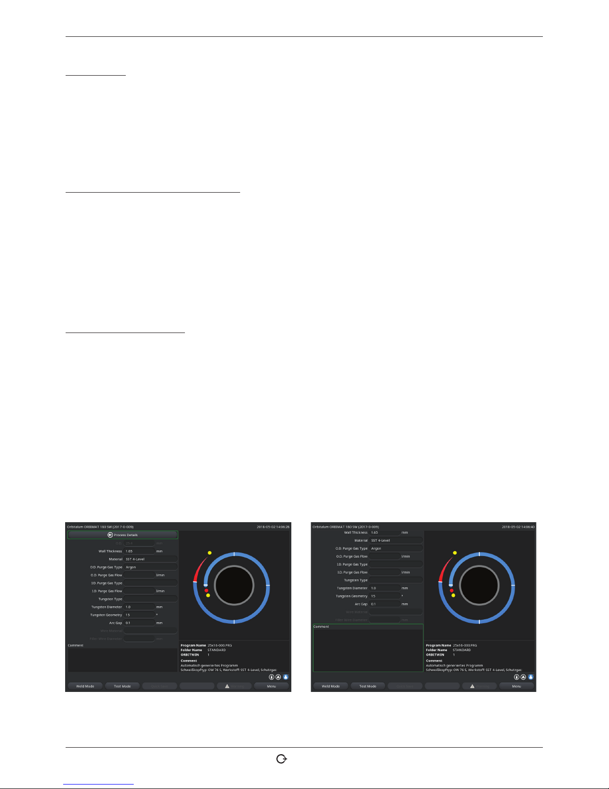
ORBIMAT 180 SW | Operating instructions Operation
(17.09.18) OW_ORBIMAT_180SW_BA_850060202_00_EN orbitalum tools GmbH , D-78224 Singen , www.orbi talum.com, Ph one +49 (0) 77 31 792-0 57
Renaming data
1. In the main menu select the "Program Manager".
2. Press softkey 4 "Rename" .
The selected file is indicated by a field highlighted in yellow.
3. The complete test is marked and can be renamed freely by using the keyboard or by double-clicking on the touch
screen.
Deleting data on the external memory card
X Same procedure as for "Deleting data"
8.10.2 Entering comments and application data ("Process details")
Useful information on individual parameters (material, gas type, electrode, etc.) and comments (for example a description
of the seam preparation, an angle setting of the electrode with adapter) about a procedure can be entered for the operator.
This information may be required for ensuring consistent results when the procedure is executed. These notes and comments are procedure-based.
Entering notes and comments
Several possibilities are available for entering notes and comments:
Either:
1. Select "System settings", then "Program settings" and subsequently "Process details" in the main menu.
2. Various parameters can now be added individually.
or:
1. In the respective welding procedure select the "Basic adjustments".
2. Select "Process details".
3. Various parameters can now be added individually.
A comment field appears in the display.
Fig. 28: Process details Fig. 29: Comments
4. Highlight the input field, enter the text and save.
Page 58

Operation ORBIMAT 180 SW | Operating instructions
58
orbitalum tools GmbH, D-78224 Sing en, www.or bitalum.com, P hone +49 (0) 77 31 792-0 (17.09.18) OW_ORBIM AT_180SW_BA_85 0060202_00 _EN
8.10.3 Working using USB
Supported storage media:
• USB storage media
X Ensure that the memory card has "FAT formatting".
Available functions:
• Saving and reading procedures.
• Saving of logs and procedures for further processing externally with special external software (OrbiProg CA)
• Backing up, restoring and updating system data. These system data are essentially the operating software itself,
the library of the available weld heads, the auto programming database and the various operating languages of the
software.
A USB stick symbol is displayed in the bottom right-hand corner of the display.
The USB stick symbol is not displayed?
X Remove the USB medium and insert it again. The USB stick recognition can take up to 30 seconds.
Write/read logs to/from memory cards:
Logs are always saved on the external memory card, as they are generally only used externally, for example on a PC
with the "OrbiProgCA" program.
Activating logs for a weld process
D Connect the USB medium.
1. In the main menu, press softkey 1 "Weld" or softkey 2 "Test ".
2. Select the "Yes" option in the Save log files" field.
During the welding process, the logs are saved on the external memory card.
If an external memory card is not inserted, an error message appears at the end of the welding process.
To always activate saving of the logs for a procedure:
X Save the procedure with activated option.
Reading and evaluating a log
D External software "OrbiProgCA" installed on a PC.
X Connect the USB medium to the PC.
The logs can also be displayed in the display of the machine.
X Display data of the logs (actual current values, weld speed and arc voltage) as a table in the display.
Page 59

ORBIMAT 180 SW | Operating instructions Operation
(17.09.18) OW_ORBIMAT_180SW_BA_850060202_00_EN orbitalum tools GmbH , D-78224 Singe n, www.orbi talum.com, Ph one +49 (0) 77 31 792-0 59
8.10.4 Viewing and printing data
Configuring the printer
D External printer connected, if applicable.
All the printers that can be selected are displayed in a list under "System adjustments".
X Us the rotary knob to select the desired printer.
Printer selection is also possible via "Basic settings" in the process under "Print log files".
If "Print log files" is set to "Off ", the list of possible printers is grayed out.
X Select "Internal" for an internal printer.
– or –
Select "USB" for an external printer.
A symbol for the printer is displayed in the bottom right of the display.
Viewing and printing saved procedures and log files
1. In the main menu, select "Print".
2. Press one of the following buttons:
Folder tree: This function prints the available structure of
the folders created in the system just like on a PC.
Procedure overview: Here, you are provided with a tabular
overview of all the procedures available on the machine,
however without the procedure parameters.
One procedure: Here you have to select an individual procedure via the folder structure which is then printed.
Log file overview: Prints the tabular overview of all the
available procedures.
Fig. 30: Overview of the log files of a procedure
All logs for a procedure: You proceed to a procedure using the folder structure here as well. Now, all logs which were
generated when welding with this procedure are printed.
One procedure: You go to a procedure using the folder structure here as well. You are now presented with the overview
of all created logs with this procedure displayed as follows:
Each protocol has a unique number generated when the data record is saved (at the end of the current welding process),
which is comprised of the current date and time.
Example (see Fig.): Log file with the number 20180302103517 (3/2/2018 at 10:35 p.m. and 17 seconds).
The logs are identified by color:
Green identifier with check mark:
All measured actual values lie within the monitoring limits for alarm and abort.
Page 60

Operation ORBIMAT 180 SW | Operating instructions
60
orbitalum tools GmbH, D-78224 Sing en, www.or bitalum.com, P hone +49 (0) 77 31 792-0 (17.09.18) OW_O RBIMAT_180S W_BA_ 850060202_0 0_EN
Yellow identification and exclamation mark:
An alarm message was output during welding. The alarm limit values specified in the monitoring limits were undershot
or overshot. The process was not aborted.
Red identification with X:
Welding was aborted. The monitoring limits were overshot/undershot or the operator initiated a "STOP".
If you now want to print an individual log after viewing it, select it. The machine will print a corresponding log with the
respective active printer (internal or external).
Printing a log directly after welding
If the "Direct printing" function is used, the data are not saved. The data are deleted after printing.
The function for saving can be activated additionally.
To print a log without using a memory card or saving the data, proceed as follows:
X Select the "Yes" option for "Print log files" in the "Welding" status.
Once the process is complete, the log is automatically printed by the active printer.
8.10.5 Editing data on a PC with the "OrbiProgCA" supplementary software
Using the external software, the procedure and log files generated by Orbitalum welding units of the entire ORBIMATseries (180 SW, 160/250 C, 165/300 CB, 165/300 CA) can be saved and printed on an external PC.
In the case of data from the CA and SW units, procedures can also be edited and the adjusted procedures transferred
back to the machine.
All the procedures and logs can be printed in the PDF format or exported as .xls files.
8.11 Updating and backup functions for the software
Updating and backup functions for the following software components:
• Operating software (system) of the machine
• Auto programming files
• Data of the individual weld heads (weld head list)
• Files of the different operating languages (language files)
The software components can be updated, saved and restored individually and independently of one another. To edit
several software components, the steps must be carried out individually for each software component.
When executing the described functions for updating and saving the software, write, read and copy
processes are carried out between the internal memory and an external storage medium.
X Ensure that the machine is connected with the network during theses actions.
X Ensure that the machine is not switched off by the main switch or by the EMERGENCY-STOP
function. The operating software can be damaged due to incomplete transfer of the data, and it
might not be possible to start the machine again in this case.
Page 61

ORBIMAT 180 SW | Operating instructions Operation
(17.09.18) OW_ORBIMAT_180SW_BA_850060202_00_EN orbitalum tools Gmb H, D-78224 Sing en, www.orb italum.com, P hone +49 (0) 77 31 792-0 61
8.12 Updating software components
Update with a new version of Orbitalum (can be obtained via Internet)
1. Connect the USB stick obtained from Orbitalum.
2. In the main menu, select "System data" > "Update".
3. Select the software component.
4. Follow the instructions on the display.
The update lasts a few minutes, and it may be necessary to restart the machine.
8.13 Saving software components
Save the existing version on a USB stick.
After saving, the USB stick can be read in using the "Update" function if necessary.
Recommendation:
X Save all the software components (system, auto programming, header list and language files).
1. Connect the USB stick.
2. In the main menu, select "System data" > "Save".
3. Select the software component.
4. Follow the instructions on the display.
8.14 Restoring software components
In case of problems with new program versions or a faulty update, the software can be reset to the version previously
used.
1. In the main menu, select "System data" > "Restore".
2. Select the software component.
3. Follow the instructions on the display.
8.15 Working in other languages
Currently, the following languages are available in the standard scope of delivery of each CA and SW power source:
German, English, US English, Spanish, French, Italian, Polish, Hungarian, Danish, Turkish, Russian, Chinese, Japanese,
Korean, Czech, Finnish, Greek, Dutch, Portuguese, Slovak, Swedish.
8.15.1 Changing the language
1. In the main menu, select "System settings" > "Language".
2. Select and confirm the desired language.
The display changes to the main menu with the selected language.
Page 62

Operation ORBIMAT 180 SW | Operating instructions
62
orbitalum tools GmbH, D-78224 Sing en, www.or bitalum.com, P hone +49 (0) 77 31 792-0 (17.0 9.18) O W_ORBIMAT_18 0SW_BA _850060202 _00_EN
Did you select the wrong language?
If the wrong language was selected and you can no longer understand the text in the display, proceed as follows:
1. Press softkey 6.
The system switches to the main menu.
2. In the main menu, select the last entry.
The "System settings" menu appears in the display.
3. In the submenu, select the last entry.
The "Language" menu appears in the display.
The list of available languages appears.
4. Select the correct language and confirm.
8.15.2 Printing data in another language
When the language is changed, all the output messages, parameter names etc. are translated to
the selected language.
Comments on the procedures or logs which were entered by the operator are not translated.
The procedures and logs are printed in the respective selected language of the operating software.
Printing a procedure on the machine
1. Change the language of the software to the desired language.
2. Print the procedure.
Printing the procedure on a PC
1. Save the procedure to a USB stick.
2. Open the procedure on the PC with the "OrbiProgCA" software and set the language.
3. Print the procedure.
Printing a log
1. Change the language of the software to the desired language.
2. Save the log.
3. Print the log.
8.15.3 Creating a new operating language
A new language file can be created in cooperation with Orbitalum.
8.16 Importing programs from other Orbitalum power sources
This allows procedures to be imported from Orbitalum devices which are either no longer being produced or which work
with a different operating system.
A procedure import to any CA and SW machine is possible from the following units:
• ORBIMAT 160 C, 250 C, 300 C
• ORBIMAT 165 CB, 300 CB
During importing, the procedures are transferred to the format of the OM 165/300CA or 180 SW respectively and can
then be used in the machine. Conversion in the other direction (procedure from the CA for use in the machines mentioned
above) is not possible, with the exception of the CA generation. Here all the procedures are fully compatible.
Page 63

ORBIMAT 180 SW | Operating instructions Operation
(17.09.18) OW_ORBIMAT_180SW_BA_850060202_00_EN orbitalum tools GmbH , D-78224 Singen , www.orbi talum.com, Pho ne +49 (0) 77 31 792-0 63
8.16.1 Importing procedures
1. Save the procedures to be transferred at the initial machine onto a USB stick.
2. For OM 160 C, OM 250 C or OM 300 C: An adapter from PCMCIA to a medium which is readable by the card reader of
the CA machine (CF, SD, SM, MMC, Sony Memory Stick) is required.
If the procedures are saved on an external PC:
Z Transfer the procedures to a USB stick. Create a "PROGRAM" folder in the process.
This structure is required for identifying the procedures on the SW.
Z Copy the procedures to this folder.
Z Copy the folder to the top level of the USB stick.
3. Connect the USB stick.
The USB stick symbol is displayed at the bottom right in the display.
4. In the main menu, select "System settings" > "Service" > "Import procedures".
The folder structure of the machine appears in the display.
Z To create a new folder, select "New folder", enter a name and confirm.
5. Select the folder.
The data are transferred and converted in the internal memory of the machine. The original procedure names, comments etc. are retained on the USB stick.
8.17 Special keyboard commands
The following commands can be entered on the external or virtual keyboard.
VER Display the software version.
SER Display the service screen.
SLO Switches the slope representation from % (standard) to seconds.
8.18 Operation of the system with other mains voltages
The OM 180 SW machine features a "wide range" input for the mains voltage (input voltage).
The machine can be used in the voltage range from 90 - 260 V at a frequency of 50 - 60 Hz.
For operation on, for example, 115 V (or any other voltage in the range stated above), the operator does not need to switch
anything or make any settings or adjustments.
In 115 V operation, higher input currents arise with otherwise even loading of the machine. The weld current is automatically limited to 120 A if a mains voltage of less than 200 V AC is active.
The machine detects the mains voltage automatically and does not permit currents over 120 A to be entered when programming the system.
Procedures containing current values over 120 A cannot be started.
X Ensure that an appropriate power plug is used for the power connection.
Page 64

Service and troubleshooting ORBIMAT 180 SW | Operating instructions
64
orbitalum tools GmbH, D-78224 Sing en, www.or bitalum.com, P hone +49 (0) 77 31 792-0 (17.09.18) OW_O RBIMAT_180S W_BA_ 850060202_0 0_EN
9. SERVICE AND TROUBLESHOOTING
9.1 Performing service work
X In the main menu select "System settings" > "Service".
The following display appears:
Fig. 31: Service menu
9.1.1 Pumping out coolant
Use when changing the coolant and emptying the tank in case of longer machine standstill
1. Connect the drain hose on the flow connection (blue).
2. Lead drain hose into a suitable container to catch the coolant water (approx. 2.2 liters).
3. Press the "Coolant pump on" button.
A message appears. The coolant is pumped out of the flow connection of the machine (blue) without the coolant sensor
in the return line being able to interrupt the process. To protect the pump against dry running, this process is limited in
time to approx. 30 seconds.
4. Select "Cancel" when the coolant is fully pumped out to avoid unnecessary dry running of the pump.
If the tank is not pumped empty:
X Start the process again.
For further information please refer to the "Commissioning" section (see chap. 7.5, p. 25).
9.1.2 Performing motor calibration
Use to check and correct the motor speed.
If several weld heads of the same type are used, a motor calibration should be carried out repeatedly before use.
If different weld head models are used, this is not required, as the machine saves a separate deviation for each head
model.
Continuously large and constantly different speed deviations are an indicator of a defect in the power source or weld
head that cannot be compensated via motor calibration.
Page 65
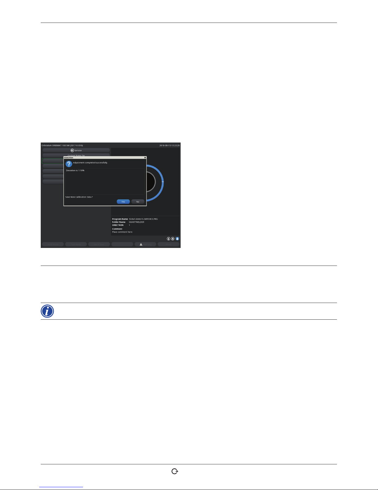
ORBIMAT 180 SW | Operating instructions Service and troubleshooting
(17.09.18) OW_ORBIMAT_180SW_BA_850060202_00_EN orbitalum tools GmbH , D-78224 Singen , www.orbi talum.com, Ph one +49 (0) 77 31 792-0 65
1. Press the "Calibrate motor" button.
The rotor moves to the home position and then carries out one complete revolution at a speed which is realistic for the
welding process. The time is measured during the revolution. The (actual) speed which can be calculated is compared to
the default value. The deviation is displayed in the speed in percent.
Properly calibrated heads generally mean deviations under 1%.
A message appears: "Save new calibration data??"
2. If the deviation is less than 1%: Confirm message with "No".
3. If the deviation is greater: Confirm the message with "Yes" and save the value.
The machine is aware of the fault of the current connected weld head and compensates for it in the process.
Fig. 32: Motor calibration
WARNING
When a display appears (see Fig. 32), the weld head can be calibrated!
1. Ensure that the head can rotate freely and that there is no danger of injury.
2. Message: Confirm "Weld head ready for calibration?" with "Yes".
The weld head starts running.
The calibration can be aborted at any time by pressing the rotary knob.
Motor calibration is only possible with heads that have a limit switch.
Page 66

Service and troubleshooting ORBIMAT 180 SW | Operating instructions
66
orbitalum tools GmbH, D-78224 Sing en, www.or bitalum.com, P hone +49 (0) 77 31 792-0 (17.09.18) OW_O RBIMAT_180S W_BA_ 850060202_0 0_EN
9.1.3 Adjusting an external printer
Adjust the printing of data when using an external (A4) printer.
Example: Printing data on letter paper.
1. Press the "External printer setup" button.
The following display appears:
2. Select and highlight fields and enter the desired
values.
Fig. 33: Printer – Set tings (external)
9.1.4 Switching on an internal printer
Inserting a new paper roll
This function is used exclusively to insert a new paper roll in the internal printer.
1. Switch on the "Internal printer on" button.
The button for the is activated.
2. Open the printer hood and cover of the printer.
3. Remove the empty cardboard roll with the shaft. Remove any paper still
present in the printer by pressing the button on the printer (line feed). Do
not pull on the paper here!
4. Slide a new paper roll onto the shaft and insert it into the recess of the
housing provided for holding the shaft until the shaft latches in audibly.
Put the paper roll on in such a manner that the paper rolls off to the back.
Put on the shaft as shown on the label in the paper compartment.
5. Cut off paper start straight and insert it into the printing unit.
6. Move paper forward by pressing the line feed button.
D not pull the paper through by hand!
7. Guide the paper through the slot in the cover and close the cover again.
Page 67

ORBIMAT 180 SW | Operating instructions Service and troubleshooting
(17.09.18) OW_ORBIMAT_180SW_BA_850060202_00_EN orbitalum tools GmbH , D-78224 Singe n, www.orbi talum.com, Ph one +49 (0) 77 31 792-0 67
Changing an ink ribbon
1. After changing the cover, push the part of the ink ribbon cassette marked
"PUSH".
The ink ribbon comes out of the drive shaft on the opposite side.
2. Remove the ink ribbon upward.
3. Using the rotary knob (see arrow for rotation direction) which protrudes
on one side, tighten the external part of the new ink ribbon and insert the
cartridge into the printer.
4. Insert the free end of the ink ribbon into the slot through which the paper is
also led out.
The paper is guided between the ink ribbon cartridge and the free end of the ink ribbon.
5. Tighten the ink ribbon again if necessary and close the printer hood.
9.1.5 Printing a test page
X Press the "Print test page" button.
A test page with a mixed character set is output on the respectively activated printer (internal or external).
9.1.6 Service screen
View the current status of all digital or analog input and output signals of the control computer.
• Digital In: Current values of the digital inputs of the computer
• Digital Out: Current values of the digital outputs of the computer
• Analog In: Current values of the analog inputs of the computer
• Analog Out: Current values of the analog outputs of the computer
• Actual Val: Display of the current actual value of the running process calculated from the information of the analog
inputs or serial inverter interface
1. Press the "Service screen" button.
The following display appears:
2. Press the "Service Screen" button again.
The graphical view of the current weld procedure appears
in the display.
Displaying the Service screen during a running welding
process
X Enter letter sequence SER (for SERVICE) on the exter-
nal keyboard.
The Service screen for the running welding process appears in the display.
Fig. 34: Service screen
Page 68

Service and troubleshooting ORBIMAT 180 SW | Operating instructions
68
orbitalum tools GmbH, D-78224 Sing en, www.or bitalum.com, P hone +49 (0) 77 31 792-0 (17.09.18) OW_O RBIMAT_180SW_BA _850060202 _00_EN
9.1.7 Info
Information on the software version currently used and the Serial No. of the machine.
View Info
X Enter the letter sequence VER (for VERSION) on the keyboard.
9.2 Possible application/operating errors
9.2.1 Uneven weld seam ("current fluctuations")
Observation
Weld seam uneven
Possible causes
• Current fluctuations as cause
The OM 165 CA unit, for example, compensates possible current fluctuations in the mains in the range from 85–260
Volt.
If you do not receive an error message from the system during welding, the weld current is, with 99% certainty,
within the limit values set for the respective procedure.
• Pipe tolerances
• Uneven weld seams can occur if classic forming gases (which contain up to 30% hydrogen in addition to nitrogen)
are used with cassette heads inside the pipe. The hydrogen enters the welding pocket in an undefined quantity and
affects the welding result as an energy carrier "randomly".
Remedy
X Always use the same gas inside the pipe as in the weld head.
9.2.2 Annealing colors inside/outside
Possible causes
• Annealing colors arise only as a result of a reaction between the base material and another substance under the
effect of a high temperature introduced into the material by the arc. This other substance can take the form of oxygen, humidity or other impurities.
• Parts of grinding disks that remain on the workpiece as residue.
• Annealing colors at the start of the seam: Possibly gas pre purge time too short. Annealing colors gradually fade as
welding progresses.
• Annealing colors at the end of welding: Gas post purge too short or (closed) weld head possibly opened too early.
• Depending on the design type, more annealing colors occur on the outside of the pipes with open weld heads (TP
series) than with cassette heads.
• TP weld heads invariably react with more sensitivity to any drafts present. A draft can "blow away" the gas cover,
thereby causing extreme annealing colors.
Remedy
X Clean pipe ends with a suitable solvent which evaporates without leaving residue (for example acetone).
X Ensure that the pipe ends are bare metal.
X Remove any and all oils and greases (from sawing or bending).
X Ensure that the following parameters are set:
– Gas quantity set sufficiently long, sufficient volume.
– Approx. 7 l/min for the weld gas and approx. 2–3 l/min for the forming gas
– Gas pre purge time/gas post purge time set optimally.
Page 69

ORBIMAT 180 SW | Operating instructions Service and troubleshooting
(17.09.18) OW_ORBIMAT_180SW_BA_850060202_00_EN orbitalum tools GmbH , D-78224 Singen , www.orbitalum.co m, Phone +49 (0) 77 31 792- 0 69
9.2.3 Wide seam and no weld penetration
When welding without a filler wire, is the seam unusually "wide" without going "deep"?
Does increasing the current amplify the effect?
Is proper weld penetration (even on comparatively thinner walls) not possible?
Possible causes
The so-called "Marangoni effect".
In stainless steel, the percentage component of sulfur is always limited upward, as sulfur forms inclusions (manganese sulfide) which lead to small craters and other defects and which ultimately reduce the corrosion resistance of the
material. For this reason, the sulfur content is limited, for example to a maximum of 0.030%. With this level of sulfur,
welding is no problem.
If the sulfur content is reduced further (approx. 0.005% or lower), the so-called "convection streams" in the melt pool
(in simplified terms) tend to flow more horizontally and on the surface. This leads to widening of the seam without
penetration.
Remedy
X Carry out a material analysis for confirmation.
X Change the material if appropriate (it may be sufficient to just change the batch).
X Weld with filler wire so that a correspondingly higher sulfur content arises in the melting pool thanks to the wire.
9.2.4 Uneven seam/hole formation at the end of welding
Do the weld seams look as if the torch "moved sideways" in an uncontrolled fashion?
Does the seam not remain centered over the joint, instead pulling to one side or moving "back and forth"?
Possible causes and remedies
• When welding pipe and molded part: "Marangoni effect".
The sulfur content tends to be high with materials for machining. The effect is seen on one side of the pipe joint
with the result of a seam which is heavily asymmetrical to the joint. The root inside the pipe is then often formed
completely outside an next to the pipe joint.
If the seam regularly wanders off to the side only in one or two places when welding, the corresponding different
material composition in the base material and in the seam is responsible for the effect at a longitudinal pipe seam.
X Shorten the arc gap slightly.
• Gas quantity set too high (weld gas or forming gas):
If an excessive gas quantity is set for small cassette heads (especially OW12), turbulence occurs in the pocket,
which can lead to an extremely irregular arc. The same applies if too much forming gas is used and it comes out at
the weld joint at relatively high pressure.
X Regulate the gas quantity.
• Excessively high forming gas pressure:
Heavy outward bulging of the seam with a type of "hollow groove" inside the pipe. Hole formation also often occurs
at the end of welding if the excessive pressure of the gas can only be "relieved" over the liquid melt pool. With cassette weld heads in particular, liquid metal dripping in the head can cause considerable consequential damage.
X Regulate the forming gas pressure.
• Worn electrode without proper grinding:
The beginning point of the arc often "dances" back and forth on the electrode. With a poor-quality electrode, lateral
migration of the arc from the electrode can be observed now and then. The reason for this can be that the alloy
components in the base material are not evenly distributed.
X Grind the electrode properly.
Page 70

Service and troubleshooting ORBIMAT 180 SW | Operating instructions
70
orbitalum tools GmbH, D-78224 Sing en, www.or bitalum.com, P hone +49 (0) 77 31 792-0 (17.0 9.18) O W_ORBIMAT_18 0SW_BA _850060202 _00_EN
9.2.5 Ignition problems
The ignition generator generates ignition pulses with a voltage of up to 8,000 V. These ignition pulses can be a considerable source of disruption (especially for computer-based control). The ignition pulses are introduced to the electrode
with high-voltage insulation via the hose package. Upon ignition, a current flow of potentially several hundred amperes
can arise in the weld circuit and be correspondingly disruptive (magnetic fields around the conductor and other highfrequency fields). The machine controller is shielded from these disruptive fields. If problems are occurring with the arc
ignition, malfunctioning of the computer or a corresponding defect in the system cannot be ruled out.
Information on possible electrical fault sources: see chap. 9.3, p. 71: "List of error messages".
Possible causes
• Poor electrode quality, worn or scaled electrode
• Poor ground contact (open heads – ground terminal).
• Worn weld current plug, poor contact.
• Rusty or soiled pipe surface.
• No gas, wrong gas (never use carbon dioxide, even if it is mixed with argon!) or gas pre purge time too short.
• Arc gap too large.
• Humidity in the weld head.
• Hose package too long (extensions).
Remedy
X Eliminate possible causes.
X Recommendation: Do not exceed a total hose package length of 15 m.
9.2.6 Machine does not start
If the operating voltage is active when the machine is started, the control computer starts the software.
Does nothing appear in the display after the machine is started?
Possible causes and remedies
X Check the mains connection.
X Ensure that the main switch lights up.
• Dummy plug is missing from the remote control connection.
• EMERGENCY-STOP function of a (possibly) connected remote control is activated.
X Insert the dummy plug.
X Unlock the EMERGENCY-STOP button of the remote control.
Page 71

ORBIMAT 180 SW | Operating instructions Service and troubleshooting
(17.09.18) OW_ORBIMAT_180SW_BA_850060202_00_EN orbitalum tools GmbH , D-78224 Singen , www.orbit alum.com, Pho ne +49 (0) 77 31 792-0 71
9.3 List of error messages
No. Error message Explanation/Elimination
01 Warning A "warning" appears in the display (directly below the mains voltage informa-
tion during the process). The message can be combined with the parameters of
voltage, current or speed and the "high" or "low" specification. The message
shows that the limit value specified in the monitoring limits for the alarm were
overshot or undershot for the corresponding parameter.
Example:
"Warning: Low speed": The limit value of the weld speed specified for the alarm
was reached during the "low-current time".
This can be overshooting or undershooting. If one of the abort values is also
reached, the process is aborted and another message is output.
02 Lack of gas The process was aborted due to a lack of gas.
X Check the hoses, bottle and pressure reducer.
X Check the sensor even if the gas is flowing in sufficient quantity.
The message also appears outside the welding process if the gas was switched
on using the gas/coolant button and no gas is flowing.
03 Lack of coolant The process was aborted due to a lack of coolant.
X Check hoses, coolant level in tank and pump operation.
X Check the sensor even if the coolant is flowing in sufficient quantity.
X Checking the coolant flow: To check the coolant flow pull the coolant re-
turn line from the machine.
This message also appears outside the welding process if the coolant was switched
on using the gas/coolant button and no coolant is flowing.
04 Error in ext. input A device connected to an external error input triggered the error.
If a device is not connected to the external error input:
X Deactivate the monitoring function in the system adjustments.
05 Current fault Used in connection with a deviation of the weld current.
Example: "Warning: Low current fault", see Message 01
06 Current abort The weld current has overshot or undershot the limits defined for aborting in
the monitoring limits and the process was interrupted.
X Check the limit values; they may be set too close together.
Excessive resistance in the weld circuit (ground connection, rotor, current
water cable): The machine can no longer keep the programmed weld current
(setpoint value) stable within the specified limits.
07 Low The limit value set for the low pulse of the corresponding parameter was
reached; see also Message 01.
08 Voltage The message appears as "Warning voltage". The limit values specified in the
monitoring limits for the alarm were overshot or undershot.
X Check the limit values and heed the information in "Monitoring functions"
(ssee chap. 8.9, p. 53).
Cause for excessive arc voltage:
High transition resistances in the weld circuit (plug, ground contact, etc.)
For cassette heads:
Worn current coolant cables.
09 Voltage abort The limit values for aborting specified in the monitoring limits with regard to
arc voltage are overshot or undershot.
X Check the limit values and heed the information in "Monitoring functions"
(see chap. 8.9, p. 53).
Cause for excessive arc voltage:
High transition resistances in the weld circuit (plug, ground contact, etc.)
For cassette heads:
Worn current coolant cables.
Page 72

Service and troubleshooting ORBIMAT 180 SW | Operating instructions
72
orbitalum tools GmbH, D-78224 Sing en, www.or bitalum.com, P hone +49 (0) 77 31 792-0 (17.09.18) OW_ ORBIMAT_180S W_BA_ 850060202_0 0_EN
No. Error message Explanation/Elimination
10 Speed Supplement to "Warning". The limit values specified in the monitoring limits
(warning) of the speed were overshot or undershot.
X Check the limit values.
X Check the weld head speed.
X If required, carry out motor calibration.
11 Speed abort The weld speed has overshot or undershot the limit values specified for abor-
tion in the monitoring limits and the process was aborted.
Check limit values; they may be too close together.
Possible causes for speed aborting:
Mechanically blocked, jamming or defective weld heads.
X Check whether the weld head can be moved manually (or with the remote
control).
X If required, carry out motor calibration.
12 Time limit for high-voltage
ignition exceeded
After the ignition device was switched on, an arc was not ignited within approx.
3 seconds. The process is interrupted.
Causes for failed arc ignition:
Fault in the marginal conditions of the process, e.g. forgotten ground connection (see chap. 9.2.5, p. 70 "Ignition problems").
13 Inverter Fault in serial communication (RS232) between the PC control system and
inverter.
X Switch the machine off and after approximately 30 seconds on again.
Is the fault still occurring?
X Contact your specialist dealer or Orbitalum.
14 Arc has cut out Arc ignition was successful, but the arc cut out during the process.
Causes:
• Interruption of welding circuit (contact problems, ground terminal).
• Currents too low (low pulse may not be under 5 A for standard applica-
tions!).
• Excessively low final current.
• Arc gap too large.
• Strong draft causes arc to cut out
15 Short-circuit
(current flowing, but no voltage)
The electrode has contacted the workpiece during the process.
This leads to a reduction of the arc voltage below the "standard" value (from approx. 10 V); the system detects a short-circuit regardless of the settings in the
monitoring limits.
X Eliminate the short-circuit.
X Re-grind the electrode.
X Grind out any tungsten inclusions in the weld seam.
16 Forming gas pressure When used with forming gas pressure regulation.
The actual value of the pressure deviates too strongly from the specified setpoint value (warning or process abortion).
Causes:
• Actual value too low; see interior pressure reading in display.
• Possible excessively low input pressure from bottle manometer.
X Ensure that there are no excessively large gaps (pipe joint?).
X Ensure that the plugs are sealing tightly so that pressure can build up.
X If required, set the pressure regulator on the BUP box to max. 10 bar.
X If required, correct the input pressure from the bottle manometer.
See also: Operating instructions of the BUP unit itself.
17 Error code Internal read-write error in the software.
"Error code" is followed by the error in "plain text" (see Messages 18 through
29) or a two-digit number.
X Contact the Orbitalum service.
Page 73

ORBIMAT 180 SW | Operating instructions Service and troubleshooting
(17.09.18) OW_ORBIMAT_180SW_BA_850060202_00_EN orbitalum tools GmbH, D-78224 Singen, w ww.orbita lum.com, Phone + 49 (0) 77 31 792-0 73
No. Error message Explanation/Elimination
18 An error has occurred!
Please contact our Support
Plain-text message which can appear with the "Error code" message (Message
17).
X Contact Orbitalum if the problem cannot be solved.
19 Parameter error
20 Drive not found
21 File not found
22 Path not found
23 Folder full
24 Drive full
25 Drive not ready
26 Write protection
27 File access error
28 The name contains impermis-
sible characters
29 Procedure cannot be opened
under the name
30 The version of the file does
not match. The file has been
modified!
X Reload/copy/correct file.
31 Further procedures cannot be
created!
For messages with "90%" specifications:
Resources almost used up. Additional data can still be saved.
Recommendation:
X Clean up the system by deleting or externally saving data which are no longer
required.
The number of folders and procedures per folder is limited to 100, however.
32 Over 90% of resources for
procedures used up!
33 Additional folders cannot be
created!
34 Over 90% of resources for
folders used up!
35 The procedure cannot be
loaded!
Procedure cannot be loaded after switch-on.
When the machine is switched on, the last used program is loaded. It this not
possible, (because the USB stick has been removed, for example), the default
procedure is loaded.
X Contact Orbitalum if the problem cannot be solved.
36 The procedure cannot be
saved!
A problem occurred while saving the procedures.
The error appears in "plain text" (see Messages 18 through 29) or as a two-digit
number.
37 File with inverter characteris-
tic cannot be opened!
Default values are used.
File with characteristics cannot be read. Current adjustment of the machine
ineffective.
A file generated during current adjustment is stored on the internal memory of
the machine: During calibration, a digital adjustment is carried out, where the
differences between the setpoint and actual values and the measured values of
a calibrated measuring unit can be recorded point by point and saved in a file.
If the file is not readable, the error coefficients are given the default value (= 1).
This makes the current adjustment carried out by Orbitalum ineffective.
X For applications which entail data monitoring and actual value recording,
stop working with the machine.
X Contact Orbitalum to restore the calibration data.
38 Auto programming failed!
The auto programming file
may be missing or corrupt.
Auto programming error.
Causes:
• The combination of pipe diameter and wall thickness lie outside the value
range of auto programming (for example wall thicknesses over 4 mm)
X Use other parameters.
• Data of the database on the internal memory not present or not readable.
X Contact Orbitalum to restore the data.
Page 74

Service and troubleshooting ORBIMAT 180 SW | Operating instructions
74
orbitalum tools GmbH, D-78224 Sing en, www.or bitalum.com, P hone +49 (0) 77 31 792-0 (17.09.18) OW_ORBIM AT_180SW_B A_85006 0202_00_E N
No. Error message Explanation/Elimination
39 External storage medium not
found!
Possibly no USB stick is
inserted in the USB port
Access to external USB stick not possible.
X Check whether the USB stick is recognized by the system.
X Remove the USB stick, wait briefly and insert it again. Possibly use a differ-
ent port.
X Check whether the USB stick is defective or has an unreadable format.
X Contact Orbitalum service if the problem cannot be resolved.
40 Error when saving log Software conflicts due to damaged files or files with unreadable contents.
The message is followed by the error in "plain text" (see Messages 18 through
29) or as a two-digit number.
41 Procedure file cannot be
opened!
42 Log file cannot be opened!
43 Some currents are set too
high.
They cannot be achieved with
a 115 V mains voltage!
Machine connected to mains network of less than 200 V AC. The maximum weld
current is limited to 120 A. Procedure with higher weld current has been started.
44 An error occurred while read-
ing the file FAILURES.TXT!
Internal error log ("Failures.txt" file) is not present or is damaged.
45 No weld head connected! Procedure started, no weld head connected to the machine.
Weld head connected?
• Weld head not encoded
• Voltage supply to weld head defective. The operating buttons in the weld
head are not working.
X Contact the Orbitalum service.
46 Incorrect weld head con-
nected!
The currently connected weld head is not the same as the weld head in the
started procedure.
X Select the connected weld head in the procedure.
– or –
X Connect the weld head selected in the procedure to the machine.
Are the weld head models identical, but the message appears nevertheless?
X Contact the Orbitalum service.
47 The procedure contains pa-
rameters that lie outside the
limit values for the selected
weld head!
Weld head changed in the procedure. Weld head does not match the parameters.
The weld head list of the machine contains the parameters of the weld heads
which can be connected to the machine, e.g. the maximum rotation of the rotor,
the maximum pipe diameter to be welded and the maximum permissible current.
X Adjust the parameters of the procedure to the selected weld head.
48 Motor current
>> Collision recognition
Norm. motor current
Motor current time
Transmission sluggish.
X Check the head.
X If necessary, repair the transmission.
49 Electrode replacement warn-
ing
X Replace the electrode.
50 Calibration error/fault
("Calibration aborted due to
execution error"; "Calibration
aborted due to operational error"; "Calibration aborted due
to parameter")
X Execute calibration again or restart the machine.
51 Error while copying proce-
dures or logs
X Check whether write protection is active. The drive is possible not ready.
52 Printing error. Error during
communication with the
printer
X Check the connection to the printer.
X Check the network connection.
X Refresh the printer list.
53 Settings incorrect X Check the entries.
Page 75

ORBIMAT 180 SW | Operating instructions Service and troubleshooting
(17.09.18) OW_ORBIMAT_180SW_BA_850060202_00_EN orbitalum tools Gmb H, D-78224 Singe n, www.orbitalum. com, Phone +49 (0) 77 31 792- 0 75
No. Error message Explanation/Elimination
54 Shared folder could not be
created/connected
X Check whether the shared folder is set to "Public".
X Check whether the input data are correct.
X Check whether the IP address range matches.
55 Touch screen could not be
changed
X Restart the machine.
56 CAN timeout error X Acknowledge the message with "Okay".
If the welding process is not possible:
X Contact the Orbitalum service.
57 Required current higher than
the maximum current of the
inverter
X Check the current settings.
If this error message appears repeatedly:
X Contact the Orbitalum service.
58 Weld held parameters for
wire are incorrect.
X Check the wire settings.
9.4 Status LED indicators
There are three smaller LEDs lighting green or flashing on the rear of the machine:
1. Process (CPU alive)
2. Coolant pump on or off
3. Coolant flow
LED 1 does not light up > Machine off
LED 2 does not light up > Coolant pump off
LED 3 does not light up > Coolant flow does not exist
9.5 Temporarily deactivating sensors and monitoring functions
9.5.1 Sensors
Certain sensors can be deactivated temporarily. This can make sense, for example, when a defective gas sensor is present
and work is to continue. Greater attention is required when continuing work with the machine.
The sensors cannot be deactivated permanently:
Deactivation of the sensors for gas and coolant monitoring is reset
each time the machine is switched off. The sensor is active again after the machine is started again.
9.5.2 Monitoring limits
The application of the monitoring limits can also be deactivated.
9.5.3 External input for aborting
If an external device with abort function is connected (for example residual oxygen meter), the function must be activated so that the abort signal is processed by the unit in the machine.
If an external device is not connected, the function must be deactivated.
X When deactivating sensors and monitoring limits, be aware that the corresponding monitoring function is no longer
active.
Example: With the gas sensor deactivated, the welding process is no longer interrupted if the gas bottle is empty.
X Deactivate sensors only in cases where this is absolutely necessary.
Page 76

Service and troubleshooting ORBIMAT 180 SW | Operating instructions
76
orbitalum tools GmbH, D-78224 Sing en, www.or bitalum.com, P hone +49 (0) 77 31 792-0 (17.09.18) OW_ORBIM AT_180SW _BA_85 0060202_00 _EN
1. In the main menu, select "System settings" > "System adjustments".
The following display appears:
2. To deactivate, select the option "No" at "Gas flow sen-
sor", "Coolant flow sensor".
3. To deactivate the warnings and the process aborting
select the option "No" at "Use of parameter limits".
4. Select the option "Yes" at "External input for abort"
and a connected external device.
5. Press softkey 3 ("Save").
Fig. 35: System adjustments
9.6 Setting the date and time
1. In the main menu, select "System settings" > "System adjustments".
The following display appears:
2. Highlight, activate and enter values for the "Year",
"Month", "Day", "Hour", "Minute" and "Second".
3. Press softkey 3 ("Save").
Fig. 36: System adjustments
Page 77

ORBIMAT 180 SW | Operating instructions Maintenance and troubleshooting
(17.09.18) OW_ORBIMAT_180SW_BA_850060202_00_EN orbitalum tools GmbH, D-78224 Singen, w ww.orbita lum.com, Phone + 49 (0) 77 31 792-0 77
10. MAINTENANCE AND TROUBLESHOOTING
10.1 Instructions for care
X Do not use lubricants or sliding agents.
X Ensure that no dirt particles or small items enter the transmission (head inside) (the transmission is open at the
head end for design reasons).
X If the surfaces are soiled, use only residue-free cleaning agents for cleaning.
10.2 Maintenance and care
The following instructions for care depend, if not stated otherwise, strongly on the usage of the welding power supply.
INTERVAL ACTIVITY
Daily
X Check the coolant in the tank (OM 180 SW) and, if necessary, top up.
Frequent topping up of the coolant may be necessary if the weld heads are
changed frequently.
1. After changing a weld head, ensure that it is completely filled with coolant
(let run for approx. 3 minutes – button: GAS/Coolant).
2. Check the coolant level and refill if necessary.
X If anti-freeze is used: Supplement with the coolant appropriately.
X Wipe off the display with a slightly damp cloth. Do not use cleaning agents.
Monthly X Clean the machine fully from the outside.
X Check the power cable, power plug and machine for mechanical damage.
X Clean the weld heads and check the mains cable.
Recommendation:
X Carry out motor calibration (even if the weld heads are suspected to be run-
ning properly).
Every six months 1. Pump out all the coolant.
2. Add fresh tap water and pump out all of this filling as well.
3. Fill the tank with coolant OCL-30.
Annually X Have inverter calibration carried out by the Orbitalum Service. Have the
BGV-A3 test carried out by Orbitalum or a certified body.
Page 78

Maintenance and troubleshooting ORBIMAT 180 SW | Operating instructions
78
orbitalum tools GmbH, D-78224 Sing en, www.or bitalum.com, P hone +49 (0) 77 31 792-0 (17.09.18) OW _ORBIMAT_180S W_BA_ 850060202_ 00_EN
10.2.1 Storage
X If the machine will be unused for a longer period of time, dismantle the machine and store it in a suitable place.
X Recommendation: Carry out the following activities before storage:
1. Clean the machine.
2. Remove the coolant.
For this purpose, loosen the coolant return line of the weld head on the back of the unit and
pump out the coolant supply into a container with the pump.
Storage conditions
• Relative humidity <70%
• Temperature range: -20 ... +40 °C, protected from dust
10.3 Servicing/Customer service
To order spare parts, refer to the separate spare parts list.
For troubleshooting, please contact the branch responsible directly.
Please indicate the following details:
• Type of machine: ORBIMAT 180 SW
• Machine No.: (see type plate)
Page 79

ORBIMAT 180 SW | Operating instructions EC Declaration of Conformity
(17.09.18) OW_ORBIMAT_180SW_BA_850060202_00_EN orbitalum tools GmbH , D-78224 Singen, w ww.orbit alum.com, Phone +49 (0) 77 31 792- 0 79
11. EC DECLARATION OF CONFORMITY
EG-Konformitätserklärung
Declaration of conformity
Dichiarazione di conformità
Déclaration de conformité
Declaración de conformidad
Orbitalum Tools GmbH
Josef-Schüttler-Straße 17
78224 Singen, Deutschland
Tel.: +49 (0) 77 31 792-0
Fax: +49 (0) 77 31 792-524
According to machine guideline 2006/42/EG II A (MaschR) and the EMC Directive 2014/30/EU.
Die Bauart der Maschine:
The fol lowing produc t:
Il seguente prodotto:
Le produit suivant:
El produ cto siguiente :
OM 180 SW Orbital Welding Power Source* incl. weld head
* Incl. all accessor y items optionally available from Orbitalum Tools, e.g.
ORBIT WIN, BUP Control, ORB 1001, ORBmax, ORBICOOL, OT-DVR, etc.
Seriennummer:
Series number:
Numero di serie:
Nombre de série:
Número de serie:
Baujahr / Yea r / Anno / Année / A ño:
ist ent wickelt, ko nstruier t und gefer tigt in Übe reinstimmun g mit folgend en EG-Rich tlinien:
was des igned, cons tructed an d manufact ured in accorda nce with the fol lowing EC guid elines:
è stata p rogetta to costruit o e commerciali zzato in osse rvanza de lle seguent i Diretti ve:
a été dess iné, produit e t commerciali sé selon les Di rectives s uivantes:
ha sido pro yectado con struido y com ercializad o bajo obser vación de la s siguientes D irectiva s:
EG-Maschinen-Richtlinie 2006/42/EG (MaschR)
EMV-Richtlinie 2014/30/EU
Folgende harmonisierte Normen sind angewandt:
The fol lowing harmo nized norms hav e been applied :
Le segu enti norme ar monizzate ov e applicabili:
Les normes suivantes harmonisées où applicables:
Las sig uientes nor mas armoniza das han sido apli cadas:
DIN EN ISO 12100:2011-03
DIN EN ISO 13849-2:2013-02
DIN EN 60204-1:2007-06
DIN EN 60974-1:2014-09
DIN EN 60974-2:2013-11
DIN EN 50445:2009-02
Authorised to compile the technical file is Mr. Gerd Riegraf, Orbitalum Tools GmbH, D-78224 Singen.
Singen, 01.06.2018 Markus Tamm
Managing Director
Marcel Foh
Business Development Manager
EG-KONFORMITÄTSERKLÄRUNG
Page 80

NORTH AM ERICA
USA
E.H. W achs
600 Kn ightsbri dge Parkwa y
Lincol nshire, IL 6 0069
USA
Tel. +1 84 7 537 8800
Fax +1 847 520 1147
Toll Free 8 00 323 818 5
NORTHEAST
Sales , Service & Rental Cen ter
E.H. W achs
1001 L ower Landi ng Road, Su ite 208
Black wood, New J ersey 08012
USA
Tel. +1 85 6 579 8747
Fax +1 856 579 8748
SOUTHEAST
Sales , Service & Rental Cen ter
E.H. W achs
171 Jo hns Road, Unit A
Greer, So uth Caroli na 29650
USA
Tel. +1 86 4 655 4771
Fax +1 86 4 655 4772
WEST COAST
Sales , Service & Rental Cen ter
E.H. W achs
5130 Fu lton Drive, Unit J
Fairfie ld, Califo rnia 9453 4
USA
Tel. +1 707 439 3763
Fax +1 707 4 39 3766
GULF CO AST
Sales , Service & Rental Cen ter
E.H. W achs
2220 So uth Philip pe Avenue
Gonza les, LA 707 37
USA
Tel. +1 22 5 644 778 0
Fax +1 225 644 7785
HOUSTON SOUTH
Sales , Service & Rental Cen ter
E.H. W achs
3327 D aisy Street
Pasad ena, Texas 77 505
USA
Tel. +1 7 13 983 0784
Fax +1 71 3 983 0703
CANADA
Wachs C anada Ltd
Easte rn Canada S ales, Ser vice & Rent al Center
1250 J ourney’s End Circle, Uni t 5
Newma rket, Ontar io L3Y 0B9
Canada
Tel. +1 90 5 830 8888
Fax +1 905 830 6050
Toll Free: 888 785 200 0
Wachs C anada Ltd
Wester n Canada S ales, Serv ice & Renta l Center
5411 8 2 Ave NW
Edmon ton, Alber ta T6B 2J6
Canada
Tel. +1 78 0 469 6402
Fax +1 780 463 0654
Toll Free 8 00 661 4235
EUROPE
GERMANY
Orbitalum Tools GmbH
Josef-Schuettler-Str. 17
78224 Si ngen
Germany
Tel. +49 (0) 77 31 - 792 0
Fax +49 (0) 77 31 - 792 5 00
UNITED KINGDOM
Wachs U K
UK Sal es, Rental & Service C entre
Units 4 & 5 Naviga tion Park
Road O ne, Winsfor d Industri al Estate
Winsf ord, Cheshi re CW7 3 RL
United Kingdom
Tel. +4 4 (0) 1606 861 423
Fax +44 (0) 1606 556 3 64
ASIA
CHINA
Orbitalum Tools
New Ca ohejing In ternationa l
Busin ess Centre
Room 28 01-B, Bui lding B
No 391 Gui Ping Ro ad
Shang hai 200052
China
Tel. +86 (0) 21 52 30 37-5 1
Fax +86 (0) 21 52 30 37-58
INDIA
ITW In dia Pvt. Ltd
Sr.no. 23 4/235 & 245
Plot n o. 8, Gala #7
India land Globa l Industri al Park
Hinjawadi-Phase-1
Tal-Mul shi, Pune 4 11057
India
Tel. +9 1 (0) 20 32 00 25 39
Mob. + 91 (0) 91 00 9 9 45 78
AFRICA & M IDDLE EA ST
UNITED ARAB EMIRATES
Wachs M iddle East & Africa Op erations
PO Box 2 62543
Free Zon e South FZS 5, ACO6
Jebel Ali Free Zone (South-5), D ubai
United Arab Emira tes
Tel. +97 1 4 88 65 21 1
Fax +97 1 4 88 65 212
worldwide | sales + service
© Orbit alum Tools GmbH | E N 850 060 202_00 | R ev. 0918 | Print ed in Germany
We value your opinion! Please send us your comments and queries.
The ITW ORBITAL CUTTING & WELDING group provides global
customers one source fo r the finest in pipe & tu be cutting, beveling
and orbital welding products.
Orbital cutting, beveling
and welding machines for
high-purity process piping.
Porta ble weld prep
machine tools for
industrial applications.
>> tools@or bitalu m.com
>> www.orbitalum.com
>> sales@ehwachs.com
>> www.ehwachs.com
For more information about us >> ww w.itw -ocw.com
 Loading...