

Page 1
Operating instructions
For responsible bodies and persons using the machine
Pipe Cutting and Beveling Machines
GFX 3.0
GFX 6.6
Machine no.
To work safely with this machine, please
read through the operating instructions
in full before initial operation. Retain the
operating instructions for future reference.
Code 790 144 762 | EN | Tr anslation of orig inal operating instruc tions
Page 2

All rights reser ved, in particular the rights of duplication and distribution as well as translation. Duplication and reproduction in any form
(print, photocopy, microfilm or electronic) require the written permission of Orbitalum Tools GmbH.
Page 3

(18.12.17) OC_GFX_BA_790144762_00_EN orbitalum tools Gmb H, D-78224 Singe n, www.orbi talum.com, Tel . +49 (0) 77 31 792-0 3
GFX 3.0, GFX 6.6 | Operating instructions
1. About these instructions ......................................5
1.1 Warning messages .....................................5
1.2 Further symbols and displays .....................5
1.3 Abbreviations ............................................5
2. Information and safety instructions for the
responsible body .................................................6
2.1 Requirements for the responsible body .......6
2.2 Using the machine .....................................6
2.2.1 Proper use .......................................6
2.2.2 Improper use ...................................6
2.2.3 Machine constraints .........................7
2.2.4 Shutting down the machine ..............7
2.3 Environmental protection/disposal .............7
2.3.1 Chips and gear lubricant oil .............7
2.3.2 Electric tools and accessories ..........7
2.3.3 Return of accumulators and
batteries ..........................................8
2.4 Basic safety instructions ............................8
2.5 Warning symbols .....................................11
3. Product design ...................................................12
3.1 Pipe Cutting and Beveling Machine
GFX 3.0 ....................................................12
3.2 Pipe Cutting and Beveling Machine
GFX 6.6 ....................................................13
3.3 Accessories .............................................14
3.3.1 Saw blades and bevel cutters .........14
3.3.2 Quick-mounting plate with screw
clamps ..........................................14
3.3.3 Tripod ............................................14
3.3.4 Pipe feeder base unit and
extension unit ................................15
3.3.5 Mobile Workstation ........................ 15
3.3.6 Durable storage and shipping case ... 16
3.3.7 Saw blade lubricant GF TOP ............16
3.3.8 Saw blade lubricant GF LUB ............16
3.3.9 Warning symbols ...........................16
4. Features and scope of application .......................17
4.1 Features ..................................................17
4.1.1 Motor ............................................17
4.1.2 Additional saw blade clamping
point for cutting tube elbows only .... 17
4.1.3 Line laser to determine cut-off point ...17
4.1.4 Plug connection with quick-
disconnect coupler ......................... 17
4.1.5 Sliding clamping jaws with
stainless-steel clamping surfaces ...18
4.1.6 Multifunctional wrench ..................18
4.1.7 Other outstanding features ............18
4.2 Scope of application ................................19
4.2.1 Application range ...........................19
5. Technical specifications .....................................20
5.1 Pipe Cutting and Beveling Machines GFX ..... 20
5.2 Line laser ................................................20
6. Initial operation .................................................21
6.1 Checking the parts of delivery .................21
6.2 Included with the machine .......................21
7. Storage and transport ........................................22
7.1 Transporting the machine .........................22
7.1.1 Supplying the machine in the
transport crate ...............................22
8. Set-up and assembly .........................................23
8.1 Fitting the machine onto the workbench ...24
8.1.1 Mounting directly on the
workbench without quick-
mounting plate ..............................24
8.1.2 Mounting on the workbench
with quick-mounting plate
with screw clamps ..........................24
8.1.3 Mounting on the workbench
with quick-mounting plate
without screw clamps .....................25
8.2 Mounting the line laser ............................26
8.3 Changing the batteries of the line laser .....26
8.4 Saw blade clamping point 1:
Fitting the saw blade/bevel cutter ............27
8.4.1 Inserting the saw blade ..................27
8.4.2 Inserting the saw blade/bevel
cutter combination or a bevel
cutter ............................................28
8.5 Saw blade clamping point 2:
Fitting the saw blade ................................28
8.5.1 Inserting the saw blade ..................29
8.6 Adjusting the tube dimension ...................29
8.6.1 Setting the tube dimension
with a scale ...................................29
8.6.2 Setting the tube dimension
without a scale ..............................30
8.6.3 Setting the tube dimension
when using an additional cutter ......30
9. Operation .........................................................31
9.1 Shutting down (even in an emergency) .....32
9.2 Selecting the speed levels ........................32
9.3 Cutting tubes ...........................................33
9.4 Beveling pipes ........................................34
9.5 Cutting and beveling pipe
simultaneously ........................................34
9.6 Cutting tube elbows .................................34
10. Servicing, maintenance, troubleshooting ............35
10.1 Maintenance ............................................35
10.1.1 Line laser .......................................35
10.2 What to do if ...?
General trouble shooting ..........................36
10.3 Servicing/customer service ......................36
11. EG Declaration of Conformity ..............................37
TABLE OF CONTENTS
Page 4

Page 5
(18.12.17) OC_GFX_BA_790144762_00_EN orbitalum tools Gmb H, D-78224 Singe n, www.orbi talum.com, Tel . +49 (0) 77 31 792-0 5
GFX 3.0, GFX 6.6 | Operating instructions About these instructions
1. ABOUT THESE INSTRUCTIONS
To allow quick understanding of these instructions and safe handling of the machine, all the warning messages, notes
and symbols used in these instructions are presented here along with their meaning.
1.1 Warning messages
In these instructions, warning messages are used to warn you against the dangers of injury or material damage.
Always read and observe these warning messages!
This is a warning symbol. It should warn you against dangers of injury.
Follow all instructions which are identified with this safety symbol in order to avoid injuries or death.
Warning symbol Meaning
DANGER
Direct danger!
Non-observance could result in death or critical injury.
[ Restrictions (if applicable).
X Measures to prevent danger.
WARNING
Possible danger!
Non-observance could result in serious injury.
[ Restrictions (if applicable).
X Measures to prevent danger.
ATTENTION
Dangerous situation!
X Non-observance could result in minor injuries.
ATTENTION Dangerous situation!
X Non-observance could result in material damage.
1.2 Further symbols and displays
Symbol Meaning
IMPORTANT
NOTE
Notes: Contain particularly important information for comprehension.
Instruction: You must take notice of this symbol.
1. Request for action in a sequence of actions: You have to do something here.
Single request for action: You have to do something here.
Conditional request for action: You have to do something here if the specified condition is met.
1.3 Abbreviations
Abbr. Abbreviations
GFX 3.0 Pipe Cutting and Beveling Machine for tubes having up to 3" outer diameters
GFX 6.6 Pipe Cutting and Beveling Machine for tubes having up to 6.6" outer diameters
Page 6

6
orbitalum tools GmbH, D-78224 Sing en, www.or bitalum.com, Tel . +49 (0) 77 31 792-0 (18.12.17) OC_G FX_BA _790144762_0 0_EN
Information and safety instructions for the responsible body GFX 3.0, GFX 6.6 | Operating instructions
2. INFORMATION AND SAFETY INSTRUCTIONS FOR THE
RESPONSIBLE BODY
2.1 Requirements for the responsible body
Workshop/outdoor/field application: The responsible body is responsible for safety in the danger zone around the
machine, and should allow only qualified personnel to enter the zone or operate the machine in the danger zone.
Employee safety: The safety regulations described in chap. 2 must be observed and work must be carried out with
safety in mind using the prescribed protective equipment.
2.2 Using the machine
2.2.1 Proper use
• The machine should be exclusively used for the cutting and beveling of materials and tube
dimensions as specified in chap. 4.2, p. 19.
• The machine can be screwed onto the workbench.
• The machines must only be operated using the voltage levels specified on the drive identification
plate and in the "technical data" (see chap. 5, p. 20).
• Only the GF10 motor (Code 790 144 382 and 790 144 383) should be used as the drive.
• The drive motor may only be used in connection with the machine.
• The machine may only be used on tubes and containers that are empty, unpressurized, do not
have explosive atmospheres and are not contaminated.
Proper use also includes the following:
• observing all safety instructions and warning messages included in these operating instructions
• carrying out all inspection and maintenance work
• sole use in the original condition with original accessories, spare parts and materials
• processing only materials set out in the operating instructions.
2.2.2 Improper use
• A use other than that defined under "proper use" or a use that goes beyond this or the specified
constraints shall be considered improper use due to the potential risks involved.
• The responsible body shall be solely responsible for damages that arise through improper use
and the manufacturer shall assume no liability whatsoever.
• No tools should be used that have not been authorized by the manufacturer for this machine.
• The removal of safety equipment is not permitted.
• Do not misuse the machine.
• The machine is not intended for use by private consumers.
• The technical values defined for normal operation must not be exceeded.
• Do not use the machine as a drive for applications other than those listed under proper use
(chap. 2.2.1).
Page 7

(18.12.17) OC_GFX_BA_790144762_00_EN orbitalum tools Gmb H, D-78224 Singe n, www.orbi talum.com, Tel . +49 (0) 77 31 792-0 7
GFX 3.0, GFX 6.6 | Operating instructions Information and safety instructions for the responsible body
2.2.3 Machine constraints
• Keep your working area clean. Disorder or unlit working areas can lead to accidents.
• The workplace can be in tube preparation, in plant construction or in the plant itself.
• A radial space requirement/freedom of movement of approx. 2 m around the machine is required for people.
• Work lighting: min. 300 lux.
• Operator age: at least 14 years old and without physical impairments.
• Operated by one person.
• Climate conditions: temperature range for machine operation: –15 °C to 40 °C (< 80% rel. humidity).
• Only work with the machine in dry surroundings (not in misty, rainy or stormy conditions).
2.2.4 Shutting down the machine
Information on the EMERGENCY STOP or the shutting down function, see chap. 9.1, p. 32.
2.3 Environmental protection/disposal
2.3.1 Chips and gear lubricant oil
Dispose of chips and used gear lubricant oil according to the regulations.
2.3.2 Electric tools and accessories
Discarded electric tools and accessories contain large quantities of valuable raw and synthetic
materials that can be recycled. Therefore:
• Electrical (electronic) devices that are marked with the symbol at the side may not be
disposed of with household waste in accordance with EU regulations.
• By actively using the available return and collection systems, you actively contribute to the
reuse, recycling and utilization of electrical (electronic) devices.
• Used electrical (electronic) devices contain parts that must be handled selectively according
to EU regulations. Separate collection and selective treatment is the basis for environmentfriendly disposal and the protection of human health.
• Appliances and products that you bought from us after August 13, 2005 will be disposed of
in accordance with legal standards after they have been supplied to us at no cost.
• We may refuse to accept old appliances that pose a risk to human health or safety due to
contamination produced during use.
• The end user is responsible for disposing of used appliances introduced to the market
before August 13, 2005. Please contact a disposal center near you for this purpose.
• Important for Germany: our products may not be disposed of in municipal disposal sites as
they are only used for industrial purposes.
(as per RL 20 02/96/EC)
Page 8

8
orbitalum tools GmbH, D-78224 Sing en, www.or bitalum.com, Tel . +49 (0) 77 31 792-0 (18.12.17) OC_G FX_BA _790144762_0 0_EN
Information and safety instructions for the responsible body GFX 3.0, GFX 6.6 | Operating instructions
2.3.3 Return of accumulators and batteries
• Accumulators and batteries that are marked with the adjacent symbol may not be disposed of
with household garbage as per EU Directive 91/157/EEC.
• In the case of accumulators and batteries containing hazardous materials the chemical sign
for the heavy metal contained is specified below the refuse bin:
Cd = Cadmium Hg = Mercury Pb = Lead
• Valid for Germany: The end consumer is obliged to return defective or used accumulators
and batteries to the distributor or to the returning facilities set up to this purpose.
Cd
2.4 Basic safety instructions
The machine (hereinafter referred to as the GFX 3.0 or GFX 6.6) is a state-of-the-art machine designed for safe use.
The risks involved in using the machine are described in the operating instructions below. Using this machine in a
way other than that described in these instructions can lead to serious physical injury and material damage.
Therefore:
• Observe warning messages at all times.
• Keep complete documentation close by the machine.
• Generally valid regulations for the prevention of accidents must be observed.
• Observe country-specific regulations, standards and guidelines.
• Always ensure that the machine is in good working order. Observe the maintenance information (chap. 10, p. 35).
• Only operate the machine if all the safety equipment such as the restart inhibitor, overload protection and chips
guard are in good working orderand the machine is firmly positioned. Check whether the substrate is able to take
sufficient loads.
• Report any unusual machine behavior to the person responsible immediately.
• Only use the dimensions and materials specified in these instructions. Other materials should be used only after
consulting with Orbitalum Tools customer service.
• Use only original tools, spare parts, materials and accessories from Orbitalum Tools.
• Repair and maintenance work on the electrical equipment may only be carried out by a qualified electrician.
• At the end of each working cycle, before transportation, changing tools, cleaning and performing any maintenance,
adjustment or repair work, switch off the machine, allow it to run to a stop and pull the mains plug.
• Do not carry the machine by the cable and do not use the machine to pull out the plug except in an emergency.
• Protect the cable from heat, oil and sharp edges (chips).
• During operation, keep hands away from the tools.
• Check that the tube is correctly clamped.
• Switch on the machine only when the tube has been clamped.
• Do not use the machine in wet surroundings. Only work in canopied surroundings.
• In extreme conditions of use, conductive dust can settle inside the machine. For this reason and for better safety,
an on-site SPE-PRCD or ground-fault circuit is required between the mains network and the machine, to be installed
and tested if necessary by a professional electrician.
• When working with the machine wear safety shoes (as per EN ISO 20345 at least S1), safety goggles (as per DIN EN
166 Class 2, basic strength S), snug-fitting safety gloves (as per DIN EN 388, Class 2 resistance to abrasion, cut
resistance Class 3, tear resistance Class 2, perforation resistance Class 3 and as per EN 407 at least Performance
level 1 against contact heat) and hearing protection (as per DIN EN 352-4 or comparable).
• Do not use click-in socket outlets and click-in power plugs (blue CEE power plugs) for power connection, otherwise
the EMERGENCY STOP does not function. The user must check whether the power plug can be pulled out of the
outlet by the cable (shutdown, see chap. 9.1, p. 32).
• Do not use angled power plugs.
Page 9
(18.12.17) OC_GFX_BA_790144762_00_EN orbitalum tools Gmb H, D-78224 Singe n, www.orbi talum.com, Tel . +49 (0) 77 31 792-0 9
GFX 3.0, GFX 6.6 | Operating instructions Information and safety instructions for the responsible body
NOTE The recommendations concerning "Personal protective equipment" only
apply to the product being described. Other requirements resulting from
the ambient conditions on-site or of other products, or from combining with
other products, are not taken into account. These recommendations do not
in any way release the responsible body (employer) from its statutory health
and safety at work obligations towards its employees.
DANGER
If the mains cable is damaged, live parts may cause death if touched directly!
Fatal electric shock.
[ Keep the mains cable of the tube saw motor away from the saw blade and/or bevel cutter.
[ Do not let the cut-off tube piece drop in an uncontrolled manner.
[ Do not run the machine unattended.
X During processing, always keep an eye on the position of the mains cable.
X Secure the falling tube piece.
X Keep the machine clean. Always remove lubricant residues from the machine.
DANGER
Damaged insulation!
Fatal electric shock.
[ Do not screw any indicators or signs to the drive motor.
X Use stickers.
DANGER
Metal dust can collect in the motor housing and cause loss of insulation!
Fatal electric shock.
X Depending on the level of contamination, clean the machine at least once a day using the brush
supplied.
DANGER
Damaged plug!
Fatal electric shock.
[ Do not use adapter plugs with ground protected electrical tools.
X The machine connector plug must fit the socket.
DANGER
Risk of danger through the use of the machine outdoors!
Fatal electric shock.
[ Do not use the machine outdoors.
DANGER
Danger! The electrical motor can overheat with operation of less than 230 V network!
Serious injury or death.
X Only use the machine in the specified temperature range.
DANGER
Grounded body!
Fatal electric shock.
X Avoid contact with grounded surfaces such as tubes, heating, cookers or refrigerators.
DANGER
Loose/baggy clothing, long hair or jewelry can get caught in rotating machine parts!
Serious injury or death.
X Wear tight-fitting clothing when using the machine.
X Tie up long hair to prevent it from being caught.
DANGER
Defective safety components due to soiling, breakage and wear!
The failure of safety components can cause physical injury.
[ Do not misuse the cable, e.g. such as using it to suspend or carry the machine.
X Replace defective safety components immediately and check them daily to ensure proper operation.
X Have an expert replace defective power cables immediately.
X Clean and perform maintenance on the machine after each use.
X Keep cables away from heat, oil, sharp edges and moving equipment parts.
X Inspect the machine daily for visible signs of damage or defects, and have them repaired by a
specialist if necessary.
Page 10

10
orbitalum tools GmbH, D-78224 Sing en, www.or bitalum.com, Tel . +49 (0) 77 31 792-0 (18.12.17) OC_G FX_BA _790144762_0 0_EN
Information and safety instructions for the responsible body GFX 3.0, GFX 6.6 | Operating instructions
WARNING
Flying parts/breaking tool!
Diverse physical injuries and material damage.
[ Do not process the tube while it is loose in the vice.
[ Never use a damaged or deformed saw blade and/or bevel cutter.
[ In the event of tool breakage with a new tool, do not enter the old cut because the tool can
break again.
X Clamp the tube to be cut into the vice.
X Immediately replace worn-out tools.
X Ensure that the cutting tools are correctly fitted.
X Tube dimension must be set correctly. During cutting, the saw blade must saw through the
entire tube wall.
X Avoid breaking tool through low (adequate) feed force, correct dimension (see chap. 8.6, p. 29)
and speed (see chap. 9.2, p. 32) settings.
X Hold on to the motor unit tightly by the handle, and guide it with low (adequate) feed force during
the machining process.
WARNING
Falling objects or tilting and bending tubes!
Irreversible crushing.
X Wear safety shoes (in accordance with EN ISO 20345, at least S1).
X Place sufficient supports under the tube.
X Transport the machine as shown in chap. 7.1, p. 22.
WARNING
Danger caused by vibration and unergonomic, monotonous work!
Discomfort, tiredness and disruptions to the locomotor system.
Limited ability to react, and cramps.
X Do relaxation exercises.
X Ensure activity is varied.
X Assume an upright, fatigue-free and comfortable body position during operation.
WARNING
Pressing the ON-OFF switch unintentionally!
Diverse physical injuries and material damage.
X At the end of each working cycle, before transportation, changing tools, cleaning and perform-
ing any maintenance, adjustment or repair work, switch off the machine, allow it to run to a
stop and pull the mains plug.
WARNING
Dangerous laser radiation!
The eye retina or eye vision can be impaired.
[ Do not look at the laser beam or view it using optical instruments.
[ Do not point the laser beam at other people.
[ Do not misuse the line laser and do not remove from the tube saw.
X Ensure that the line laser is switched off during mounting/dismantling.
CAUTION!
Use of controls or adjustments or performance of procedures other than those specified herein may
result in hazardous radiation exposure.
Page 11
(18.12.17) OC_GFX_BA_790144762_00_EN orbitalum tools Gmb H, D-78224 Singe n, www.orbi talum.com, Tel . +49 (0) 77 31 792-0 11
GFX 3.0, GFX 6.6 | Operating instructions Information and safety instructions for the responsible body
2.5 Warning symbols
Observe all of the warnings and safety instructions affixed to the machines.
The following labels also appear on the machine:
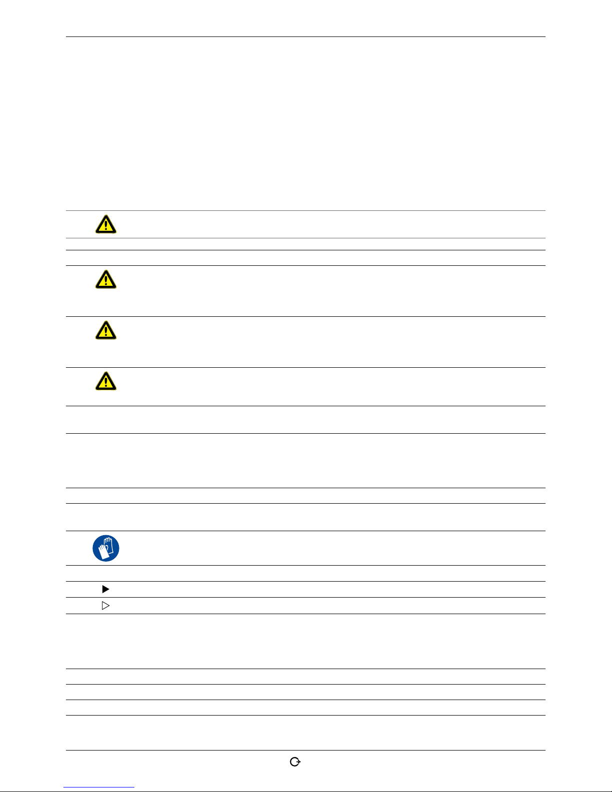
Image Position on machine Meaning Code
Motor, side INSTRUCTION:
Wear safety goggles in accordance
with DIN EN 166, ear protection in
accordance with DIN EN 352 and tightfitting safety gloves in accordance
with DIN EN 388 and EN 407.
Read the operating instructions.
790 086 200
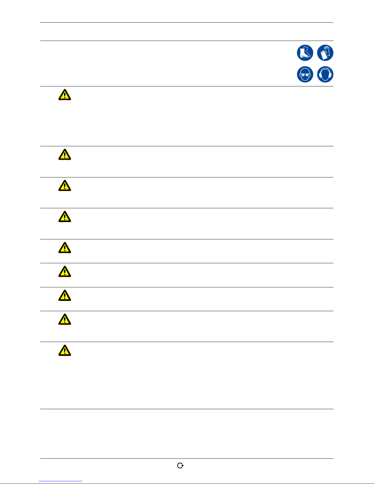
Motor, front WARNING:
Danger of being injured by sharp
cutting edges.
790 046 196
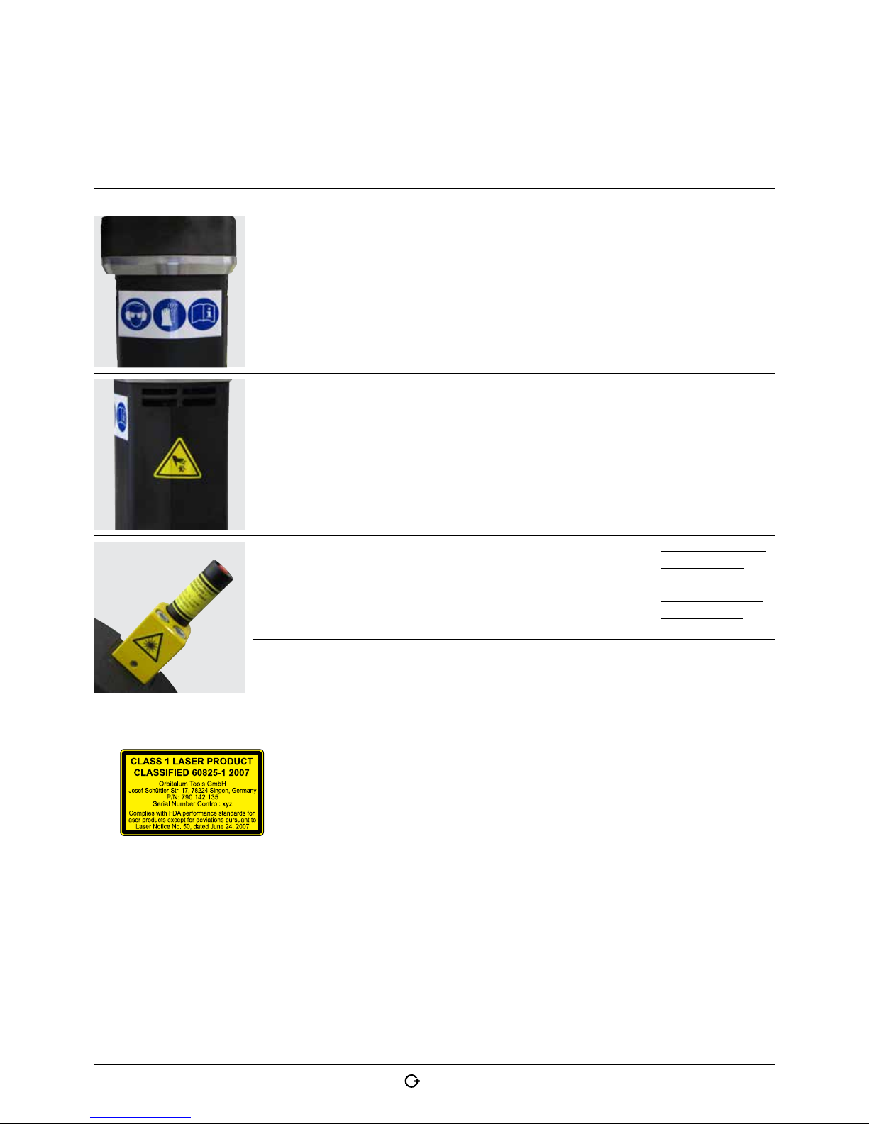
Line laser WARNING:
Laser class I.
For Laser 790 142 125
(230 V machines):
790 142 288
For Laser 790 142 135
(120 V machines):
790 142 298*
Holder indicut
(line laser)
WARNING:
Dangerous laser radiation.
790 142 289
* Warning symbol with Code 790 142 298:
Page 12
12
orbitalum tools GmbH, D-78224 Sing en, www.or bitalum.com, Tel . +49 (0) 77 31 792-0 (18.12.17) OC_GF X_BA _790144762_00 _EN
Product design GFX 3.0, GFX 6.6 | Operating instructions
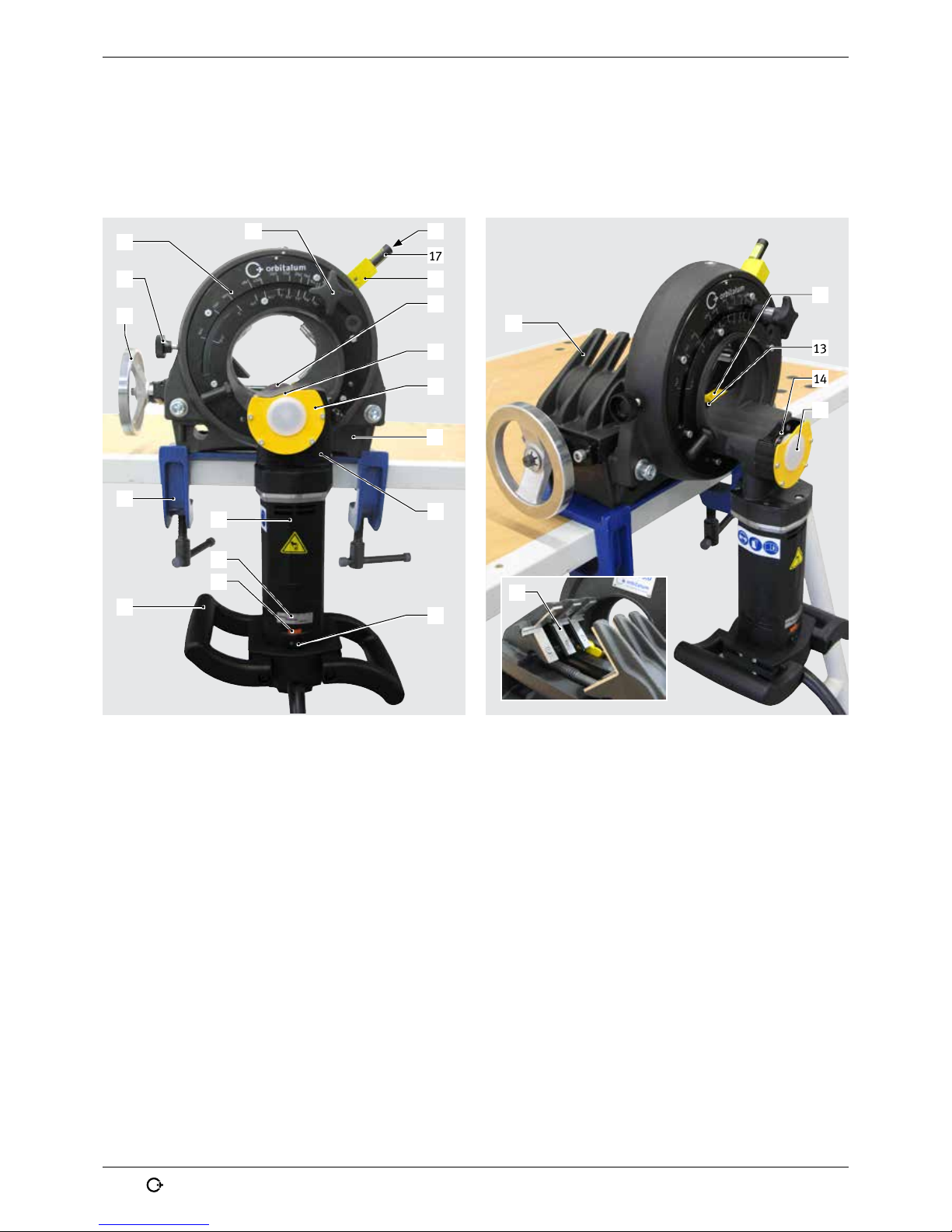
3. PRODUCT DESIGN
3.1 Pipe Cutting and Beveling Machine GFX 3.0
1
19
2
5
8
17
13
14
11
10
16
18
15
3
9
6
4
7
20
13
14
21
12
15
1. Scale for adjusting the tube dimension
2. Locking screw
3. Hand wheel for clamping jaws
4. Quick-mounting plates with screw clamps
(available as an option, see chap. 3.3.2, p. 14)
5. Motor (Details, see chap. 4.1.1, p. 17)
6. Rotating-speed indicator
7. RPM regulator
8. Motor handle
9. Motor ON-OFF switch
10. Slide housing
11. Vice
12. Chips guard, can be swiveled
13. Saw blade clamping point 1
14. Saw blade clamping point 2 (for cutting elbows)
15. Chips guard
16. Holder indicut (line laser)
17. Line laser (Details, see chap. 4.1.3, p. 17)
18. ON-OFF switch line laser
19. Star knob for setting the tube dimension
20. Cast steel clamping jaws
21. Stainless steel caps
Page 13

(18.12.17) OC_GFX_BA_790144762_00_EN orbitalum tools GmbH, D-78224 Singen, w ww.orbita lum.com, Tel. +49 (0) 7 7 31 792-0 13
GFX 3.0, GFX 6.6 | Operating instructions Product design
3.2 Pipe Cutting and Beveling Machine GFX 6.6
4
5
6
7
8
9
10
11
12
13
14
16
15
3
2
1
18
19
20
15
16
13
21
14
17
1. ON-OFF switch line laser
2. Line laser (Details, see chap. 4.1.3, p. 17)
3. Holder indicut (line laser)
4. Locking screw
5. Vice handle / Multifunctional wrench
(Details, see chap. 4.1.6, p. 18)
6. Quick-mounting plates with screw clamps
(available as an option, see chap. 3.3.2, p. 14)
7. Motor (Details, see chap. 4.1.1, p. 17)
8. Rotating-speed indicator
9. Motor handle
10. Motor ON-OFF switch
11. RPM regulator
12. Slide housing
13. Vice
14. Chips guard
15. Saw blade clamping point 1
16. Saw blade clamping point 2 (for cutting elbows)
17. Chips guard, can be swiveled
18. Scale for adjusting the tube dimension
19. Star knob for setting the tube dimension
20. Cast steel clamping jaws
21. Stainless steel caps
Page 14

14
orbitalum tools GmbH, D-78224 Sing en, www.or bitalum.com, Tel. +49 (0) 77 31 792- 0 (18.12.17) OC_G FX_BA _790144762_0 0_EN
Product design GFX 3.0, GFX 6.6 | Operating instructions
3.3 Accessories
Not included as standard.
WARNING
Danger presented by using poor-quality accessories and tools not approved by Orbitalum Tools!
Diverse physical injuries and material damage.
X Use only original tools, spare parts, materials, and accessories from Orbitalum Tools.
3.3.1 Saw blades and bevel cutters
All saw blades and bevel cutters by Orbitalum Tools are specially developed for our tube and
pipe cutters to endure maximum strain and have a maximum tool life.
A selection of 4 different saw blades and bevel cutters are available for various uses:
• Economy Range for low and non-alloy steels and cast iron tubes
• Performance Range for high-alloy steels (stainless steel)
• High-Performance Range for high-performance materials and high-alloy steels
• Premium Range especially made for stainless steel applications with extra long durability
Workable tube
materials
Al Mild steel, Cu,
CuNi, CuZn, CuSn
INOX, V2A, V4A,
304, 316 (L)
Ti, Duplex,
Inconel
Economy * *
Performance * *
High-Performance * * *
Premium *
3.3.2 Quick-mounting plate with screw clamps
To quickly fit machines to workbenches.
Ideal if changing location often.
Article Code
Quick-mounting plates with screw clamps for GFX 3.0, RA 2, RA 21 S 790 041 027
Quick-mounting plates with screw clamps for GF 4, GF 6, GFX 6.6, RA 4, RA 6,
RA 8, RA 41 Plus
790 042 027
3.3.3 Tripod
Suitable for GFX 3.0, PS 4.5, PS 6.6.
Made of aluminum.
For easy mounting of PS machines directly on the tripod with no base plate.
Space saving – fast application – easy handling.
Article Code
Tripod for GFX 3.0, PS 4.5, PS 6.6 790 048 390
Page 15

(18.12.17) OC_GFX_BA_790144762_00_EN orbitalum tools GmbH , D-78224 Singen, w ww.orbit alum.com, Tel. +49 ( 0) 77 31 792-0 15
GFX 3.0, GFX 6.6 | Operating instructions Product design
3.3.4 Pipe feeder base unit and extension unit
The pipe feeder allows you to feed long and heavy pipes effortlessly and coaxially to the tube
saws. Very sturdy and stable design with powder-coated frames and stainless steel rollers.
The ideal addition for all Orbitalum pipe cutters (with exception of 20 AVM. RA 2,
GFX 3.0, PS 4.5, PS 6.6 on request).
Advantages:
• Extremely stable and sturdy
• Fast adjustment of dimensions
• Centerline of tubes and pipes adjust easily in seconds
• Steel frame coated for maintenancefree finish
• Rollers made of stainless steel
• Extension of the Pipe Feeder possible with Extension Unit
• Saves time and money
• No contamination
• Perfect for all kinds of steel
Application range/
Technical specifications
Pipe feeder base unit Pipe feeder extension unit
Pipe OD 16 - 325 mm
0.63" - 12.8"
16 - 325 mm
0.63" - 12.8"
Dimensions approx. 185 x 105 x 50 cm
72.8" x 41.3" x 19.7"
160 x 105 x 50 cm
62.9" x 41.3" x 19.7"
Load capacity max. 400 kg / 881.8 lbs 400 kg / 881.8 lbs
Height-adjustable mounting
plate (adjusting range)
68 mm
2.68"
–
Article Code
Pipe feeder base unit 790 068 051
Pipe feeder extension unit 790 068 061
3.3.5 Mobile Workstation
For the mobile site and/or workshop. The ideal addition for all Orbitalum pipe cutters
(with exception of 20 AVM. RA 2, PS 4.5, PS 6.6 on request).
Technical specifications Mobile Workstation
Dimensions (hxlxw) 91 x 115 x 43 cm
35.8" x 45.3" x 16.9"
Load capacity max. 675 kg / 1488.1 lbs
Article Code
Mobile Workstation 790 068 071
Page 16

16
orbitalum tools GmbH, D-78224 Sing en, www.or bitalum.com, Tel. +49 (0) 77 31 792- 0 (18.12.17) OC_G FX_B A_790144762_0 0_EN
Product design GFX 3.0, GFX 6.6 | Operating instructions
3.3.6 Durable storage and shipping case
High quality padded blue shipping case. Particularly sturdy design.
Article Code
Durable storage and shipping case for GFX 3.0 790 144 019
3.3.7 Saw blade lubricant GF TOP
Synthetic high-performance lubricant for cutting and beveling machines. Increases the
tool life of the saw blade. Registered according to the NSF H2 food approval. The screwable
brush guarantees an easy and uniform application of lubricant on the saw blade.
Article Version Code
Saw blade lubricant GF TOP Tube, 180 g 790 060 228
3.3.8 Saw blade lubricant GF LUB
For cutting and beveling. Increases the tool life of the saw blade. The new ecological lubricant
is the environmentally-friendly successor to ROCOL; with a new name and improved quality.
GF LUB complies with the latest environmental guidelines and ecological standards.
The chlorine-free GF LUB can be ordered using the same article number as the previous
lubricant, ROCOL.
Article Version Code
Saw blade lubricant GF LUB Tube, 160 ml 790 041 016
3.3.9 Warning symbols
Overview of warning symbols with order numbers, see chap. 2.5, p. 11.
Page 17

(18.12.17) OC_GFX_BA_790144762_00_EN orbitalum tools GmbH , D-78224 Singen , www.orbit alum.com, Tel. + 49 (0) 77 31 792-0 17
GFX 3.0, GFX 6.6 | Operating instructions Features and scope of application
4. FEATURES AND SCOPE OF APPLICATION
4.1 Features
The GFX pipe cutting and beveling machines are distinguished by the following charact:
4.1.1 Motor
With built-in variable cutting speed and ergonomic handles.
Enables a safer operating position and cutting of tube elbows without alteration.
Other advantages:
• Electronic overload protection with integrated temperature monitor and speed control.
• A restart inhibit function prevents the machine from starting in an uncontrolled way
after it has been re-connected to the electric mains or after the voltage supply has
been re-established following a power failure.
• High performance drive (1200 W) with adjustable speed range for cutting a selection
of materials.
• Increased blade life through tachometer regulation.
• Rotating-speed indicator (3) for speed selection.
• Ergonomically positioned speed adjustment wheel (4) and ON/OFF switch (5).
5
3
4
4.1.2 Additional saw blade clamping point for cutting tube elbows only
Which saw blade clamping point to use?
Saw blade clamping point 1 Saw blade clamping point 2
Cutting tubes Cutting tube elbows only
2
1
4.1.3 Line laser to determine cut-off point
To determine the cut-off point on the tube. Ideal for checking whether the tube is adjusted to the desired cut-off point. A red line marking (1), to determine the cut-off point,
appears on the clamped tube once the red button on the line laser has been actuated.
If necessary, the tube position can be corrected until the desired cut-off point is marked.
1
4.1.4 Plug connection with quick-disconnect coupler
For easy and comfortable replacement of the power cable.
Other advantages:
• If there is a cable fracture, then the cutter motor does not have to be opened and a
qualified electrician is not required to replace the flex cable.
• As the flex cable is locked away, misuse can be prevented.
Page 18

18
orbitalum tools GmbH, D-78224 Sing en, www.or bitalum.com, Tel. +49 (0) 77 31 792- 0 (18.12.17) OC_GF X_BA _790144762_0 0_EN
Features and scope of application GFX 3.0, GFX 6.6 | Operating instructions
4.1.5 Sliding clamping jaws with stainless-steel clamping surfaces
The GFX is equipped by default with stainless-steel sliding clamping jaws and stainlesssteel clamping surfaces. The 6 stainless-steel clamping surfaces are already mounted on
the clamping jaws on delivery and prevent contact corrosion between the tube and the
clamping jaws.
4.1.6 Multifunctional wrench
Only part of the GFX 6.6. It is possible to make 3 different adjustments on the machine using this multifunctional wrench:
Vice handle Fix ture for saw blade/bevel cutter Fixture of the saw for quick-mounting plate
4.1.7 Other outstanding features
• Enhanced safety due to stationary tube and rotating tool.
• Self-centering vice.
• Right-angled, burr-free cutting surface and deformation-free tube cross-section.
• Production of standardized welding bevels.
• Cold machining process.
• Quick cutting process.
• Quick tool change.
• Easy assembly and little space required.
• Simultaneous cutting and beveling of thin-walled metal tubes.
• Optimized discharge of chips thanks to the design of the vice.
• Environmentally friendly.
• Long service life.
• Lightweight, so easy to handle.
• Increased productivity.
• Low and easy maintenance.
Page 19

(18.12.17) OC_GFX_BA_790144762_00_EN orbitalum tools GmbH, D-78224 Singen, w ww.orbital um.com, Tel. +49 (0) 77 31 79 2-0 19
GFX 3.0, GFX 6.6 | Operating instructions Features and scope of application
4.2 Scope of application
4.2.1 Application range
Type of machine GFX 3.0 GFX 6.6
Tube OD [mm]
[inch]
6.0 - 78.0
0.236 - 3.071
21.3 - 168.3
0.838 - 6.659
Wall thickness [mm]
[inch]
0.8 - 7.0
0.031 - 0.275
0.8 - 7.0
0.031 - 0.275
Tube ID min.
(Saw blade Ø 63/2.248")
[mm]
[inch]
0
0
23.0
0.905
OD range
(Saw blade Ø 63/2.248")
[mm]
[inch]
6.0 - 78.0
0.236 - 3.071
24.6 - 168.3
1.008 - 6.659
Tube ID min.
(Saw blade Ø 68/2.677")
[mm]
[inch]
0
0
18
0.708
OD range
(Saw blade Ø 68/2.677")
[mm]
[inch]
6.0 - 73.0
0.236 - 2.874
21.3 - 168.3
0.838 - 6.659
Tube ID min.
(Saw blade Ø 80/3.149")
[mm]
[inch]
–
–
6.0
0.236
OD range
(Saw blade Ø 80/3.149")
[mm]
[inch]
–
–
21.3 - 156.0
0.838 - 2.205
Tube materials Unalloyed, low-alloy and high-alloy steel, stainless steel, non-
ferrous metal, aluminum alloy, titanium alloy, composite material
and plastic
Page 20

20
orbitalum tools GmbH, D-78224 Sing en, www.or bitalum.com, Tel . +49 (0) 77 31 792-0 (18.12.17) OC _GFX _BA_79 0144762_00_EN
Technical specifications GFX 3.0, GFX 6.6 | Operating instructions
5. TECHNICAL SPECIFICATIONS
5.1 Pipe Cutting and Beveling Machines GFX
Type of machine GFX 3.0 GFX 6.6
Dimensions (lxhxw) [mm]
[inch]
570 x 280 x 330
22.44 x 11.02 x 12.99
575 x 671 x 350
22.64 x 26.42 x 13.78
Weight incl. vice,
without clamping shells
[kg]
[lbs]
28.500
62.83
74.400
164.02
Power [W] 1200 1200
Protection class [class] II II
Built-in electronic variable cutting
speed with restart inhibitor
[Rpm] 30 - 200 30 - 200
Versions (1-phase AC) [V, Hz]
[V, Hz]
230 V, 50/60 Hz EU
120 V, 50/60 Hz US
230 V, 50/60 Hz EU
120 V, 50/60 Hz US
Vibration level as per EN 50144 [m/s²] < 2.5 < 2.5
Sound pressure level at the
workplace
*)
[dB (A)] 79.7 79.7
* The noise level was measured under normal operating conditions in accordance with EN 23741.
5.2 Line laser
Dimensions (l x w) [mm]
68 x 15
[inch]
2.7 x 0.59
Weight [g]
30
[lbs]
0.012
Power, total emitted [mW]
5
[HP]
5x10⁻⁶
Power for classification [μW] < 390
Beam range [m]
1
[inch]
3.937
Wave length [nm]
650
Operating voltage [
V DC
]
2.8 to 4.5
Operating current [mA] 20
Operating temperature [°C] -10 to 40
Storage temperature [°C] -40 to 80
Laser cla [class] 1
Battery type 2 x LR44 / AG13
Page 21

(18.12.17) OC_GFX_BA_790144762_00_EN orbitalum tools GmbH, D-78224 Singen, w ww.orbital um.com, Tel. +49 (0) 77 31 79 2-0 21
GFX 3.0, GFX 6.6 | Operating instructions Initial operation
6. INITIAL OPERATION
6.1 Checking the parts of delivery
• Check delivery for completeness and damage caused by transport.
• Report any missing parts or damage caused by transport to your supplier immediately.
6.2 Included with the machine
Subject to modifications.
Pcs. Article GFX 3.0 GFX 6.6
1 Pipe Cutting and Beveling Machine x x
1 Wooden transportation crate x x
1 Saw blade, Code 790 ... ... 041 035 ... 042 064
1 Quick-mounting plate without screw clamps* – x
1 Set of stainless steel caps** x x
1 Line laser with holder and fastening screws*** x x
1 Tool key set x x
1 Tube of saw blade lubricant GF TOP (Code 790 060 228) x x
1 Set of operating instructions and spare parts list x x
* The GFX 3.0 can be mounted directly on the workbench without a quick-mounting plate. Quick-mounting plates with screw clamps for GFX 3.0
and GFX 6.6 are available optionally.
** Already mounted on the sliding clamping jaws of the GFX at delivery.
*** The line laser has to be mounted on the GFX before commissioning (mounting, see chap. 8 .2, p. 26).
Page 22

22
orbitalum tools GmbH, D-78224 Sing en, www.or bitalum.com, Tel . +49 (0) 77 31 792-0 (18.12.17) OC _GFX _BA_79 0144762_00_EN
Storage and transport GFX 3.0, GFX 6.6 | Operating instructions
7. STORAGE AND TRANSPORT
ATTENTION
Incorrect machine storage!
Diverse physical injuries and material damage.
X Store the machine in its original crate in a dry environment.
DANGER
Fatal electric shock!
X Before transportation or changing the workplace, allow the machine to run to a stop and pull the
mains plug.
WARNING
During transportation, the ON/OFF switch may unintentionally be activated causing the machine to
start up!
Diverse physical injuries and material damage.
X Before transportation or changing the workplace, allow the machine to run to a stop and pull the
mains plug.
WARNING
Heavy weight when transporting the tube saw!
Danger of being injured through.
X Transport tube saws over long stretches with corresponding lifting aids.
7.1 Transporting the machine
NOTE X Transport the GFX in a packed state in the transport crate or on a pallet with corresponding
lifting aids.
1. Pull the conveyor belt through the machine rotating body and secure with a crane (or similar lifting equipment).
2. Hold the machine at the handle and at the same time lift it out of the transport crate using the crane.
3. Use the crane to place the machine on a suitable working or mounting plate and fasten it (see chap. 8.1, p. 24).
4. Ensure that the machine stands securely.
Transport in a packed state in the transport crate or on a pallet with corresponding lifting aids (e.g. lif t truck).
Lift the machine with a crane (or similar lifting equipment) out of the
transport crate and supply it again.
7.1.1 Supplying the machine in the transport crate
1. Pull the conveyor belt through the machine rotating body and secure with a crane (or similar lifting equipment).
2. Dismantle the machine from the working or mounting plate.
3. Hold the machine at the handle and at the same time lift it using the crane.
4. Lift the machine with the crane over the transport crate and lower it.
5. Close the transport crate with a cover.
Page 23

(18.12.17) OC_GFX_BA_790144762_00_EN orbitalum tools GmbH, D -78224 Singen, ww w.orbitalu m.com, Tel. +49 (0) 77 31 792- 0 23
GFX 3.0, GFX 6.6 | Operating instructions Set-up and assembly
8. SET-UP AND ASSEMBLY
DANGER
Machine start-up due to unintentional pressing of the ON/OFF switch!
Fatal electric shock.
Diverse physical injuries and material damage.
X At the end of each working cycle, before transportation, changing tools, cleaning and performing
any maintenance, adjustment or repair work, switch off the machine, allow it to run to a stop
and pull the mains plug.
WARNING
When switching the motor on, the tube saw may revolve around the tube automatically!
Diverse physical injuries and material damage.
[ In their home position, the saw blade and/or bevel cutter must not touch the tube.
X Make sure that the slide housing is in the home position when the cutting process starts.
X Clamp the tube to be cut into the vice.
X Before switching the motor on, make sure that the gap between the saw blade and the tube is
sufficient, and that the tube is securely clamped in the vice.
X Place sufficient supports under the tube.
WARNING
Flying parts/breaking tool!
Diverse physical injuries and material damage.
[ Do not process the tube while it is loose in the vice.
[ Never use a damaged or deformed saw blade and/or bevel cutter.
[ In the event of tool breakage with a new tool, do not enter the old cut because the tool can break
again.
X Clamp the tube to be cut into the vice.
X Immediately replace worn-out tools.
X Ensure that the cutting tools are correctly fitted.
X Tube dimension must be set correctly. During cutting, the saw blade must saw through the entire
tube wall.
X Avoid breaking tool through low (adequate) feed force, correct dimension (see chap. 8.6, p. 29)
and speed (see chap. 9.2, p. 32) settings.
X Hold on to the motor unit tightly by the handle, and guide it with low (adequate) feed force during
the machining process.
WARNING
Flying, hot and sharp-edged chips, tube surfaces, cutting edges and tools!
Danger of injury to eyes and hands.
[ Do not reach into the rotating tool during working.
[ Never work without the saw chip guard mounted.
X Wear recommended protective clothing.
X Only remove chips with tight-fitting safety gloves (in accordance with DIN EN 388 and EN 407,
see chap. 2.4, p. 8).
X Make sure the chips guard is working.
ATTENTION Damage to material!
[ When using a supplemental bevel cutter do not use the clamping disc contained in the scope of
delivery of the saw.
[ Never use a damaged or deformed saw blade or cutter.
X The saw blade and/or bevel cutter must be free from chips and dirt.
X Only use original Orbitalum Tools saw blades and tools.
X Observe assembly instructions of saw blade guard. The labeling on the saw blade must always
face the tube cutter. The teeth are now arranged in the correct direction.
Page 24

24
orbitalum tools GmbH, D-78224 Sing en, www.or bitalum.com, Tel . +49 (0) 77 31 792-0 (18.12.17) OC _GFX _BA_79 0144762_00_EN
Set-up and assembly GF X 3.0, GFX 6.6 | Operating instructions
8.1 Fitting the machine onto the workbench
IMPORTANT
Warning messages are used in these instructions to warn you of possible risk of death, injury or damage to property. Always read and observe these warning messages! To ensure safe setting up and
mounting please read all the warning messages in chap. 2, p. 6 and chap. 8, p. 23 attentively.
Mount the GFX; either:
• directly on the workbench without a quick-mounting plate (see chap. 8.1.1, p. 24) or
• on the workbench with a quick-mounting plate with screw clamps (see chap. 8.1.2, p. 24) or
• on the workbench with a quick-mounting plate without screw clamps (see chap. 8.1.3, p. 25).
In addition, mounting of the GFX saws on the tripod (see chap. 3.3.3, p. 14), on the pipe feeder (chap. 3.3.4, p. 15)
or on the mobile workstation (chap. 3.3.5, p. 15) is possible (all available optionally).
8.1.1 Mounting directly on the workbench without quick-mounting plate
Only possible with the GFX 3.0.
1. Mark and punch the bolt holes on the workbench. Use the GFX 3.0 as a template.
2. Drill Ø 13 mm (0.5") holes.
3. Fit the GFX 3.0 with the provided countersunk onto the workbench.
8.1.2 Mounting on the workbench with quick-mounting plate with screw clamps
Possible with all the machines of the GFX series.
Quick-mounting plates with screw clamps are not included in the scope of delivery of the GFX series and can be retrofitted (see "Accessories", chap. 3.3.2, p. 14).
NOTE At the GFX 6.6 the quick-mounting plate has to be mounted directly on the left-hand workbench
edge, so that the vice handle (1) at the side of the GFX 6.6 can be turned in its full radius with sufficient distance to the workbench edge.
1. Fit the quick-mounting plate with the screw clamps onto the workbench.
2. Guide the tube cutter sideways onto the fitted quick-mounting plate.
3. Tighten the hexagon screw (2) so that it lies firmly on the retainer at the vice of the saw (3).
1
2
2 3
Page 25

(18.12.17) OC_GFX_BA_790144762_00_EN orbitalum tools GmbH, D-78224 Singen, w ww.orbita lum.com, Tel. +49 (0) 77 31 7 92-0 25
GFX 3.0, GFX 6.6 | Operating instructions Set-up and assembly
8.1.3 Mounting on the workbench with quick-mounting plate without screw clamps
Only possible with the GFX 6.6.
NOTE At the GFX 6.6 the quick-mounting plate has to be mounted directly on the left-hand workbench
edge, so that the vice handle (1) at the side of the GFX 6.6 can be turned in its full radius with sufficient distance to the workbench edge.
1. Mark and punch the bolt holes on the workbench. Use the quick-mounting plate as a template.
2. Drill Ø 13 mm (0.5") holes.
3. Fasten the quick-mounting plate with screws.
4. Guide the GFX 6.6 sideways onto the fitted quick-mounting plate.
5. Tighten the hexagon screw (2) so that it lies firmly on the retainer at the vice of the saw (3).
1
2
2 3
Page 26

26
orbitalum tools GmbH, D-78224 Sing en, www.or bitalum.com, Tel. +49 (0) 77 31 792- 0 (18.12.17) OC_GF X_BA _790144762_00 _EN
Set-up and assembly GF X 3.0, GFX 6.6 | Operating instructions
8.2 Mounting the line laser
IMPORTANT
Warning messages are used in these instructions to warn you of possible risk of death, injury or damage to property. Always read and observe these warning messages! To ensure safe setting up and
mounting please read all the warning messages in chap. 2, p. 6 and chap. 8, p. 23 attentively.
NOTE The line laser is supplied separately with the machine and has to be mounted on the GFX before
commissioning.
WARNING
Dangerous laser radiation!
The eye retina or eye vision can be impaired.
X Ensure that the line laser is switched off during mounting/dismantling.
1. Place the line laser on the intended location surface (1) on the housing.
2. Tighten the line laser lightly with 2 hexagon socket head screws (2) so that it can still be aligned.
3. Switch on the line laser and align it so that the line laser beam lies flush with the saw blade (3).
4. Tighten the 2 hexagon socket head screws (2) and switch the line laser off again.
1
3
2
8.3 Changing the batteries of the line laser
WARNING
It is not allowed to open, modify or to remove protective covers or housings except for line laser
battery change.
WARNING
Dangerous laser radiation!
The eye retina or eye vision can be impaired.
X Ensure that the line laser is switched off when replacing the battery.
1. Unscrew the line laser and replace the batteries (4) (Pack with 10 button cells, 1.5 V = Code 790 142 124).
2. Screw the parts of the line laser again.
4
Page 27

(18.12.17) OC_GFX_BA_790144762_00_EN orbitalum tools GmbH, D -78224 Singen, w ww.orbital um.com, Tel. +49 (0) 77 31 79 2-0 27
GFX 3.0, GFX 6.6 | Operating instructions Set-up and assembly
8.4 Saw blade clamping point 1: Fitting the saw blade/bevel cutter
IMPORTANT
Warning messages are used in these instructions to warn you of possible risk of death, injury or damage to property. Always read and observe these warning messages! To ensure safe setting up and
mounting please read all the warning messages in chap. 2, p. 6 and chap. 8, p. 23 attentively.
WARNING
Hot components!
Danger of injury to hands.
X Wear suitable safety gloves when replacing the saw blade (in accordance with DIN EN 388 and
EN 407, see chap. 2.4, p. 8).
X Lay down the tools and fastening parts rapidly.
Only use saw blade clamping point 1 to cut and bevel tubes. If you want to cutting tube
elbows, use saw blade clamping point 2 (see chap. 8.5, p. 28).
NOTE Saw blades/bevel cutters can only be fitted or replaced if no tube is
clamped in the vice. If necessary, remove the tube before fitting the
saw blade.
2
1
8.4.1 Inserting the saw blade
1. Turn the tube cutter clockwise and upwards by 180°.
2. Tighten the locking screw (2).
3. Loose the nut (5) clockwise (left-hand thread).
4. Clean the saw blade shaft (1) and vicinity with a brush.
5. Place the saw blade (3) and clamping disc (4) onto the
shaft (1).
IMPORTANT Put the saw blade onto the shaft so that the
inscription points to the machine. The toothing then points in the right direction.
6. Tighten nut (5) counterclockwise (left-hand thread).
7. Loosen the locking screw (2).
8. Turn the tube cutter clockwise and downwards to its
home position.
Page 28

28
orbitalum tools GmbH, D-78224 Sing en, www.or bitalum.com, Tel. +49 (0) 77 31 792- 0 (18.12.17) OC_GF X_BA _790144762_00 _EN
Set-up and assembly GF X 3.0, GFX 6.6 | Operating instructions
8.4.2 Inserting the saw blade/bevel cutter combination or a bevel cutter
ATTENTION
Flying parts/breaking tool!
Do not use the clamping disc (4) when using
saw blade/bevel cutter combinations or
bevel cutters!
1. Turn the tube cutter clockwise and upwards by 180°.
2. Tighten the locking screw (2).
3. Loose the nut (5) clockwise (left-hand thread).
4. Clean the saw blade shaft (1) and vicinity with a brush.
5. Place the saw blade/bevel cutter combination (3) or
bevel cutter (4) onto the shaft (1).
IMPORTANT Put the saw blade/bevel cutter combination
or bevel cutter onto the shaft so that the
inscription points to the machine. The toothing then points in the right direction.
6. Tighten nut (5) counterclockwise (left-hand thread).
7. Loosen the locking screw (2).
8. Turn the tube cutter clockwise and downwards to its
home position.
8.5 Saw blade clamping point 2: Fitting the saw blade
IMPORTANT
Warning messages are used in these instructions to warn you of possible risk of death, injury or damage to property. Always read and observe these warning messages! To ensure safe setting up and
mounting please read all the warning messages in chap. 2, p. 6 and chap. 8, p. 23 attentively.
Only use saw blade clamping point 2 to cutting tube elbows. If you want to cut or bevel
tubes, use saw blade clamping point 1 (see chap. 8.4, p. 27).
NOTE
Saw blades can only be fitted or replaced if no tube is clamped in the
vice. If necessary, remove the tube before fitting the saw blade.
2
1
Page 29

(18.12.17) OC_GFX_BA_790144762_00_EN orbitalum tools GmbH, D -78224 Singen, ww w.orbitalu m.com, Tel. +49 (0) 77 31 792- 0 29
GFX 3.0, GFX 6.6 | Operating instructions Set-up and assembly
8.5.1 Inserting the saw blade
1. Loosen the nut (5) counterclockwise.
2. Clean the saw blade shaft (1) and vicinity.
3. Place the saw blade (3) and clamping disc (4) onto the shaft (1).
IMPORTANT Put the saw blade onto the shaft so that the inscription points to the clamping disc and nut.
The toothing then points in the right direction.
4. Tighten nut (5) clockwise.
5
8.6 Adjusting the tube dimension
IMPORTANT
Warning messages are used in these instructions to warn you of possible risk of death, injury or damage to property. Always read and observe these warning messages! To ensure safe setting up and
mounting please read all the warning messages in chap. 2, p. 6 and chap. 8, p. 23 attentively.
NOTE X The steps for adjusting the tube dimension are identical for both saw blade clamping points.
8.6.1 Setting the tube dimension with a scale
1. Loosen the star knob (1).
2. Select the tube dimension on the scale (2).
3. Slide the star knob (1) in the direction of the arrow
to the desired tube dimension.
4. Tighten the star knob (1).
2
1
Page 30

30
orbitalum tools GmbH, D-78224 Sing en, www.or bitalum.com, Te l. +49 (0) 77 31 792-0 (18.12.17) OC _GFX_ BA_79 0144762_0 0_EN
Set-up and assembly GF X 3.0, GFX 6.6 | Operating instructions
8.6.2 Setting the tube dimension without a scale
1. Place the tube in the vice.
2. Slide the tube forwards until it is close to the saw
blade.
3. Clamp the tube in the vice.
4. Loosen the star knob (1) and set to the greatest possible dimension. Do not tighten.
5. Raise the motor of the tube cutter in the direction
of the arrow as if to saw until the teeth of the saw
blade protrude approx. 1.5 mm/0.059 inch (approx.
height of saw blade teeth) into the center of the
tube.
6. Tighten the star knob (1).
7. Turn the tube saw back to the home position.
1
8.6.3 Setting the tube dimension when using an
additional cutter
Steel tubes with a wall thickness of 7 mm (0.276 inch)
can be simultaneously cut and beveled.
1. Place the tube in the vice.
2. Slide the tube forwards until it is close to the additional cutter.
3. Clamp the tube in the vice.
4. Loosen the star knob (1) and set to the greatest possible dimension. Do not tighten.
5. Pull the motor of the tube saw upward in the arrow
direction as for sawing until the bevel cutter covers
the tube wall.
6. Tighten the star knob (1).
7. Turn the tube saw back to the home position.
1
8. Perform a test bevel and check the bevel
(see chap. 9, p. 31).
Bevel OK Move the star k nob (1)
slightly to the right
Move the star k nob (1)
slightly to the left
Page 31

(18.12.17) OC_GFX_BA_790144762_00_EN orbitalum tools GmbH, D-78224 Singen, w ww.orbita lum.com, Tel. +49 (0) 77 31 7 92-0 31
GFX 3.0, GFX 6.6 | Operating instructions Operation
9. OPERATION
DANGER
Machine start-up due to unintentional pressing of the ON/OFF switch!
Fatal electric shock.
Diverse physical injuries and material damage.
X At the end of each working cycle, before transportation, changing tools, cleaning and perform-
ing any maintenance, adjustment or repair work, switch off the machine, allow it to run to a
stop and pull the mains plug.
DANGER
When the slide housing is rotating, excess lubricant can get into the motor unit!
Fatal electric shock.
X Remove excess lubricant from the machine after every step.
DANGER
Unexpected start-up!
Serious injury or death.
X Before connecting the machine to the power supply, check the on/off switch is switched off.
DANGER
Loose/baggy clothing, long hair or jewelry can get caught in rotating machine parts!
Serious injury or death.
X Wear tight-fitting clothing when using the machine.
X Tie up long hair to prevent it from being caught.
WARNING
Flying parts/breaking tool!
Diverse physical injuries and material damage.
[ Do not process the tube while it is loose in the vice.
[ Never use a damaged or deformed saw blade and/or bevel cutter.
[ In the event of tool breakage with a new tool, do not enter the old cut because the tool can
break again.
X Clamp the tube to be cut into the vice.
X Immediately replace worn-out tools.
X Ensure that the cutting tools are correctly fitted.
X Tube dimension must be set correctly. During cutting, the saw blade must saw through the entire
tube wall.
X Avoid breaking tool through low (adequate) feed force, correct dimension (see chap. 8.6, p. 29)
and speed (see chap. 9.2, p. 32) settings.
X Hold on to the motor unit tightly by the handle, and guide it with low (adequate) feed force during
the machining process.
WARNING
Risk of machine and tube falling!
Irreversible crushing.
X Check the machine's position and secure it so it cannot fall.
X Place sufficient supports under the tube.
WARNING
Trapped fingers between the vice/clamping shell and tube!
Irreversible crushing.
[ Do not insert fingers between the vice/clamping shell and tube.
WARNING
Body parts can fit between the cutting tools and the tube!
Serious injury.
[ Do not place body parts between the cutting tools and the tube.
WARNING
Flying, hot and sharp-edged chips, tube surfaces, cutting edges and tools!
Danger of injury to eyes and hands.
[ Do not reach into the rotating tool during working.
[ Never work without the saw chip guard mounted.
X Wear recommended protective clothing.
X Only remove chips with tight-fitting safety gloves (in accordance with DIN EN 388 and EN 407,
see chap. 2.4, p. 8).
X Make sure the chips guard is working.
Page 32

32
orbitalum tools GmbH, D-78224 Sing en, www.or bitalum.com, Tel . +49 (0) 77 31 792-0 (18 .12.17) OC_ GFX_B A_790144762_ 00_EN
Operation GFX 3.0, GFX 6.6 | Operating instructions
ATTENTION
Restarting the machine following blockage!
Diverse physical injuries and material damage.
X In the event of a blockage, always disconnect the machine from the power supply before clearing it.
X If necessary, remove any tensioned parts before restarting the machine.
ATTENTION
Vapors when working with lubricants!
Damage to lungs, skin and the environment
X Only use original lubricant recommended by Orbitalum Tools.
9.1 Shutting down (even in an emergency)
IMPORTANT
Warning messages are used in these instructions to warn you of possible risk of death, injury or
damage to property. Always read and observe these warning messages! To ensure safe operation
please read all the warning messages in chap. 2, p. 6 and chap. 8, p. 23 attentively.
WARNING
EMERGENCY STOP function not available by unplugging the power plug!
Diverse physical injuries and material damage.
[ Do not use angled power plugs.
[ Do not use click-in socket outlets and click-in power plugs (blue CEE power plugs) for power
connection, otherwise the EMERGENCY STOP does not function. The user must check whether
the power plug can be pulled out of the outlet by the cable.
X Only use original Orbitalum Tools parts.
X Ensure free access to the power plug.
To be able to stop the machine (also in case of emergency), perform the corresponding
steps and immediately remove from the danger area, until the machine comes to a stop:
X Activate by switching the ON/OFF toggle switch (1).
If the ON/OFF toggle switch (1) fails to work:
X Remove the plug from the socket or vacate the danger zone as quickly as possible
and then unplug the power plug.
1
9.2 Selecting the speed levels
IMPORTANT
Warning messages are used in these instructions to warn you of possible risk of death, injury or
damage to property. Always read and observe these warning messages! To ensure safe operation
please read all the warning messages in chap. 2, p. 6 and chap. 8, p. 23 attentively.
Pipe material Controller setting
(2)
Spindle speed
(rpm)
High-alloy/high-quality steel 1 - 3 30 - 98
Low-alloy/high-quality steels 3 - 5 98 - 166
Construction steel 5 - 6 166 - 200
2
IMPORTANT Select a low speed for large tube diameters and wall thicknesses.
Page 33

(18.12.17) OC_GFX_BA_790144762_00_EN orbitalum tools GmbH, D -78224 Singen, w ww.orbital um.com, Tel. +49 (0) 77 31 79 2-0 33
GFX 3.0, GFX 6.6 | Operating instructions Operation
9.3 Cutting tubes
IMPORTANT
Warning messages are used in these instructions to warn you of possible risk of death, injury or
damage to property. Always read and observe these warning messages! To ensure safe operation
please read all the warning messages in chap. 2, p. 6 and chap. 8, p. 23 attentively.
1. Fit saw blade and/or bevel cutter (saw blade clamping point 1, see chap. 8.4, p. 27; saw blade clamping point 2
for cutting tube elbows see chap. 8.5, p. 28).
2. Adjust the bevel cutter to the tube dimension (see chap. 8.6, p. 29).
3. Connect tube cutter to power supply.
4. Place the tube in the vice (2).
NOTE It is advisable to support pipes whose length exceeds 1 m with
a pipe support or a pipe feeder or extension unit (chap. 3.3.4,
p. 15).
IMPORTANT For the GFX 6.6: Pull off the vice handle from the spindle before the slide housing starts rotating.
5. Slide the pipe forward in the vice until the desired pipe length is reached, mark the cutting point on the pipe by means
of the line laser (1).
6. Tighten the pipe firmly in the vice using the handwheel (3) at the GFX 3.0 or using the vice handle at the GFX 6.6.
7. Switch the saw motor on at the ON/OFF switch (4).
IMPORTANT Apply saw blade lubricant to teeth of saw blade. Repeat lubrication every 3 cuts.
Only use saw blade lubricant/paste (no oils) from Orbitalum Tools (e.g. GF LUB
or GF TOP). Keep the machine clean. Always remove lubricant residues from the
machine.
8. Set the desired speed level using the speed regulator (5) (for standard values, see chap. 9.2, p. 32).
9. Carefully turn the tube cutter in a clockwise direction until the tube wall has been pierced through.
10. Continue turning rapidly until the tube has been cut off and the marks (6) are aligned on the slide housing and body.
11. Turn the tube cutter back to its home position.
12. Switch the saw motor off again at the ON/OFF switch (4).
NOTE For continuous operation: After cutting loosen the hexagon nut on the bevel cutter to avoid damage
caused by tension.
1
3
2
6
5
4
6
Page 34

34
orbitalum tools GmbH, D-78224 Sing en, www.or bitalum.com, Tel . +49 (0) 77 31 792-0 (18.12.17) OC _GFX_ BA_790 144762_0 0_EN
Operation GFX 3.0, GFX 6.6 | Operating instructions
9.4 Beveling pipes
The necessary work steps for beveling pipes are identical to chap. 9.3, p. 33.
9.5 Cutting and beveling pipe simultaneously
The necessary work steps for simultaneously cutting and beveling are identical to chap. 9.3, p. 33. The pipe cutter
however must revolve much slower around the pipe than when cutting, since two tools are being used at the same time.
9.6 Cutting tube elbows
Pipe elbows are cut at saw blade clamping point 2 (saw blade assembly, see chap. 8.5,
p. 28). The necessary work steps for cutting tube elbows are identical to chap. 9.3, p. 33.
2
1
Page 35

(18.12.17) OC_GFX_BA_790144762_00_EN orbitalum tools GmbH , D-78224 Singen, w ww.orbit alum.com, Tel. +49 ( 0) 77 31 792-0 35
GFX 3.0, GFX 6.6 | Operating instructions Servicing, maintenance, troubleshooting
10. SERVICING, MAINTENANCE, TROUBLESHOOTING
NOTE Some of the work mentioned depends a great deal on the use and on the ambient conditions.
The cycles specified are minimum specifications. In individual cases, differing maintenance cycles
are possible. To ensure the safety of the machine, perform maintenance annually using an authorized service center with VDE testing. If the machine does not function as previously described, the
machine must also be sent into an authorized service center.
DANGER
Danger of death by electric shock!
Non-observance could result in death or serious injury.
X At the end of each working cycle, before transportation, changing tools, cleaning and perform-
ing any maintenance, adjustment or repair work, switch off the machine, allow it to run to a
stop and pull the mains plug.
DANGER
Risk of electric shock due to poor electrics!
Fatal electric shock.
X At the end of each working cycle, before transportation, changing tools, cleaning and perform-
ing any maintenance, adjustment or repair work, switch off the machine, allow it to run to a
stop and pull the mains plug.
X Repair and maintenance work on the electrical equipment may only be carried out by a qualified
electrician.
10.1 Maintenance
Time/Interval Activity
Weekly X Remove the saw blade and use the brush
to remove any saw chips.
X Lubricate the 4 points indicated by the ar-
rows (use only thin-bodied oil, no grease).
When cleaning and when
changing tools
[ Do not use compressed air to clean the
area at the end of the shaft (marked with
an arrow) as the rotary shaft seal may otherwise be damaged by chips.
X Use a cloth or brush to clean the end of
the shaft.
10.1.1 Line laser
X Own maintenance work on the laser is not permitted.
X The laser is to be returned to the factory for any maintenance or repair work that may be required.
X It is not allowed to open, modify or to remove protective covers or housings except for battery change.
Page 36

36
orbitalum tools GmbH, D-78224 Sing en, www.or bitalum.com, Tel . +49 (0) 77 31 792-0 (18.12.17) OC _GFX_ BA_79 0144762_0 0_EN
Servicing, maintenance, troubleshooting GFX 3.0, GFX 6.6 | Operating instructions
10.2 What to do if ...? – General trouble shooting
Problem Possible cause Remedy
The tube cutter will not turn. The locking screw is tight. X Loosen the locking screw.
Incorrect tube dimension. X Set the tube dimension correctly.
The saw blade is not cutting and is
slipping through.
The nut on the saw blade shaft is not
tight enough.
X Tighten the nut.
The saw blade is not cutting. The saw blade has been inserted the
wrong way round.
X Insert the saw blade so that the
labeling on the saw blade faces the
tube cutter.
The tube is not cut concentrically. The tube cutter has been incorrectly
flanged. The flange surfaces are
contaminated.
X Remove the tube cutter, clean the
fixing parts and flange surfaces,
reflange the saw.
The tube is not cut. Pipe dimension not correctly set. X Adjust the bevel cutter to the tube
dimension (see chap. 8.6, p. 29).
The clamping lever is not tightened. X Tighten the clamping lever.
The motor does not start. The auto startup inhibitor is active
because the ON switch is locked.
X Release the locking button and
press the ON switch again.
10.3 Servicing/customer service
For ordering spare parts, refer to the separate spare parts list.
For troubleshooting, please contact the branch responsible directly.
Please indicate the following details:
• Type of machine: Pipe Cutting and Beveling Machine GFX 3.0 or GFX 6.6
• Machine no. (see type plate)
Page 37

(18.12.17) OC_GFX_BA_790144762_00_EN orbitalum tools GmbH, D-78224 Singen, w ww.orbital um.com, Tel. +49 (0) 77 31 79 2-0 37
GFX 3.0, GFX 6.6 | Operating instructions EG Declaration of Conformity
11. EG DECLARATION OF CONFORMITY
EG-Konformitätserklärung
Declaration of conformity
Dichiarazione di conformità
Déclaration de conformité
Declaración de conformidad
Orbitalum Tools GmbH
Josef-Schüttler-Straße 17
78224 Singen, Deutschland
Tel.: +49 (0) 77 31 792-0
Fax: +49 (0) 77 31 792-524
According to machine guideline 2006/42/EG (MaschR) and the EMC Directive 2014/30/EU.
Die Bauart der Maschine:
The fol lowing produc t:
Il seguente prodotto:
Le produit suivant:
El produ cto siguiente :
GFX 3.0 Pipe Cutting and Beveling Machine*
GFX 6.6 Pipe Cutting and Beveling Machine*
Seriennummer:
Series number:
Numero di serie:
Nombre de série:
Número de serie:
Baujahr / Yea r / Anno / Année / A ño:
ist ent wickelt, ko nstruier t and gefer tigt in Übe reinstimmun g mit folgend en EG-Rich tlinien:
was des igned, cons tructed an d manufact ured in accorda nce with the fol lowing EC guid elines:
è stata p rogetta to costruit o e commerciali zzato in osse rvanza de lle seguent i Diretti ve:
a été dess iné, produit e t commerciali sé selon les Di rectives s uivantes:
ha sido pro yectado con struido y com ercializad o bajo obser vación de la s siguientes D irectiva s:
Maschinen-Richtlinie (2006/42/EG)
EMV-Richtlinie (2014/30/EU)
Niederspannungsrichtlinie (2014/35/EU)
Folgende harmonisierte Normen sind angewandt:
The fol lowing harmo nized norms hav e been applied :
Le segu enti norme ar monizzate ov e applicabili:
Les normes suivantes harmonisées où applicables:
Las sig uientes nor mas armoniza das han sido apli cadas:
DIN EN 60745-1: 2010.01
DIN EN ISO 12100: 2011.03
DIN EN 62841-1: 2016.07
* including all accessories of Orbitalum Tools, e.g. the tube feeder base and extension units, the mobile workstation, etc.
Authorised to compile the technical file is Mr. Gerd Riegraf, Orbitalum Tools GmbH, D-78224 Singen.
Singen, 03.08.2017 Markus Tamm
Managing Director
Marcel Foh
Business Development Manager
Page 38

Page 39

Page 40

© Orbit alum Tools GmbH | EN 79 0 144 762_00 | Rev. 1217 | Pri nted in Ge rmany
We value your opinion! Please send us your comments and queries.
worldwide | sales + service
The ITW ORBITAL CUTTING & WELDING group provides global
customers one source for the finest in pipe & tub e cutting, beveling
and orbital welding products.
Orbital cutting, beveling
and welding machines for
high-purity process piping.
Porta ble weld prep
machine tools for
industrial applications.
>> tools@or bitalu m.com
>> www.orbitalum.com
>> sales@ehwachs.com
>> www.ehwachs.com
For more information about us >> ww w.itw -ocw.com
NORTH AMERICA
USA
E.H. Wachs
600 Knightsbridge Parkway
Lincolnshire, IL 60069
USA
Tel. +1 847 53 7 8800
Fax +1 847 520 11 47
Toll Free 800 3 23 8185
NORTHEAST
Sales , Service & Rent al Center
E.H . Wachs
1001 Lo wer Landing Ro ad, Suite 208
Blackwood, New Jersey 08012
USA
Tel. +1 856 57 9 8747
Fax +1 856 579 8 748
SOUTHEAST
Sales , Service & Rent al Center
E.H. Wachs
171 Joh ns Road, Unit A
Greer, South Carolina 29650
USA
Tel. +1 864 655 4771
Fax +1 864 655 4 772
WEST COAST
Sales , Service & Rent al Center
E.H. Wachs
5130 Fulton Drive , Unit J
Fairfield, California 94534
USA
Tel. +1 707 439 3 763
Fax +1 707 439 376 6
GULF COA ST
Sales , Service & Rent al Center
E.H. Wachs
2220 South Philippe Avenue
Gonzales, LA 70737
USA
Tel. +1 225 64 4 7780
Fax +1 225 64 4 7785
HOUSTON SOUTH
Sales , Service & Rent al Center
E.H. Wachs
3414 Li lac Unit E
Pasad ena, Texas 77505
USA
Tel. +1 713 983 0784
Fax +1 713 983 0703
CANADA
Wachs Canada Ltd
Eastern Canada Sales , Service & Rent al Center
1250 Journey’s End Circle, Unit 5
Newmarket, Ontario L3Y 0B9
Canada
Tel. +1 905 83 0 8888
Fax +1 905 830 6 050
Toll Free: 88 8 785 2000
Wachs Canada Ltd
Western Canada Sales, S ervice & Renta l Center
5411 82 Av e NW
Edmon ton, Alberta T6B 2J6
Canada
Tel. +1 780 469 6402
Fax +1 780 463 0 654
Toll Free 800 6 61 4235
EUROPE
GERMANY
Orbitalum Tools GmbH
Josef-Schuettler-Str. 17
78224 Singen
Germany
Tel. +49 (0) 77 3 1 - 792 0
Fax +49 (0) 77 31 - 7 92 500
UNITED KINGDOM
Wachs UK
UK Sale s, Renta l & Service Cent re
Units 4 & 5 N avigati on Park
Road On e, Winsford Ind ustrial Estate
Winsford, Cheshire CW 7 3 RL
United Kingdom
Tel. +44 (0) 1606 861 42 3
Fax +44 (0) 1606 556 36 4
ASIA
CHINA
Orbitalum Tools
New Caohejing International
Business Centre
Room 280 1-B, Buildi ng B
No 391 Gu i Ping Road
Shanghai 200052
China
Tel. +86 (0) 21 5 2 30 37-51
Fax +86 (0) 21 52 3 0 37-58
INDIA
ITW Ind ia Pvt. Ltd
Sr.no. 23 4/235 & 245
Plot no. 8 , Gala #7
Indialand Global Industrial Park
Hinjawadi-Phase-1
Tal-Mulshi, Pune 411057
India
Tel. +91 (0) 20 3 2 00 25 39
Mob. +9 1 (0) 91 00 99 45 78
AFRICA & M IDDLE EA ST
UNITED ARAB EMIRATES
Wachs Middle Eas t & Africa Opera tions
PO Box 262 543
Free Zone S outh FZS 5, ACO6
Jebel Ali Free Zone (S outh-5), Dub ai
United Arab Emirates
Tel. +97 1 4 88 65 211
Fax +971 4 8 8 65 212
 Loading...