

Page 1

April 2010
Release 7.0
Pegasus® User’s Guide
Approved for Public Release
Distribution Unlimited
Copyright© 1996-2010 by Orbital Sciences Corporation. All Rights Reserved.
Page 2

This Pegasus® User’s Guide is intended to familiarize potential space launch vehicle users with the
Pegasus launch system, its capabilities and associated services. The launch services described herein
are available for commercial procurement directly from Orbital Sciences Corporation.
Readers desiring further information on Pegasus should contact us via:
E-mail to: baldwin.bryan@orbital.com
Telephone: (703) 433-6043
Copies of this Pegasus User’s Guide may be obtained from our website at http://www.orbital.com
Hardcopy documents and electronic (CD format) are also available upon request.
Pegasus User’s Guide
.
Release 7.0 Apr 2010 ii
Page 3

INTRODUCTION .................................................................................................................................... 1
1.
2. PEGASUS DESCRIPTION..................................................................................................................... 3
2.1. Pegasus XL Vehicle Description .................................................................................................... 3
2.1.1. Solid Rocket Motors .................................................................................................................. 3
2.1.2. Payload Fairing.......................................................................................................................... 3
2.1.3. Avionics .....................................................................................................................................4
2.1.4. Flight Termination System......................................................................................................... 5
2.1.5. Attitude Control Systems ........................................................................................................... 5
2.1.6. Telemetry Subsystem................................................................................................................ 6
2.1.7. Major Structural Subsystems.....................................................................................................6
2.1.7.1. Wing .................................................................................................................................... 6
2.1.7.2. Aft Skirt Assembly ............................................................................................................... 7
2.1.7.3. Payload Interface Systems ................................................................................................. 7
Pegasus User’s Guide
TABLE OF CONTENTS
PAGE
2.2. Orbital Carrier Aircraft..................................................................................................................... 7
3. GENERAL PERFORMANCE CAPABILITY ........................................................................................... 8
3.1. Mission Profiles ..............................................................................................................................8
3.2. Performance Capability .................................................................................................................. 9
3.3. Trajectory Design Optimization ...................................................................................................... 9
3.4. Orbit Insertion Accuracy ................................................................................................................. 9
3.4.1. Actual Pegasus Insertion Accuracies ...................................................................................... 10
3.4.2. Error-Minimizing Guidance Strategies..................................................................................... 10
3.5. Collision/Contamination Avoidance Maneuver............................................................................. 12
4. PAYLOAD ENVIRONMENTS............................................................................................................... 13
4.1. Design Loads................................................................................................................................ 13
4.2. Payload Testing and Analysis ...................................................................................................... 14
4.3. Payload Acceleration Environment .............................................................................................. 14
4.4. Payload Random Vibration Environment .....................................................................................14
4.5. Sinusoidal Vibration...................................................................................................................... 15
4.6. Payload Shock Environment ........................................................................................................ 15
4.7. Payload Acoustic Environment..................................................................................................... 15
4.8. Pressure Profile ............................................................................................................................ 16
4.9. Payload Thermal Environment .....................................................................................................16
4.9.1. Payload Processing................................................................................................................. 16
4.9.2. Transportation ......................................................................................................................... 16
4.9.3. Ground Operations at the Flightline and Launch Operations.................................................. 21
Release 7.0 Apr 2010 iii
Page 4

Powered Flight......................................................................................................................... 21
4.9.4.
4.9.5. Nitrogen Purge ........................................................................................................................ 21
4.10. Payload Electromagnetic Environment ........................................................................................ 21
4.11. Payload Contamination Control.................................................................................................... 22
5. SPACECRAFT INTERFACES.............................................................................................................. 23
5.1. Payload Fairing............................................................................................................................. 23
5.1.1. Fairing Separation Sequence .................................................................................................. 24
5.1.2. Payload Design Envelopes...................................................................................................... 24
5.1.3. Payload Access Door .............................................................................................................. 24
5.2. Payload Mechanical Interface and Separation System................................................................ 24
5.2.1. Standard Nonseparating Mechanical Interface ....................................................................... 24
5.2.2. Standard Separating Mechanical Interface ............................................................................. 24
5.3. Payload Electrical Interfaces ........................................................................................................ 29
Pegasus User’s Guide
TABLE OF CONTENTS (CONTINUED)
PAGE
5.3.1. Standard Electrical Interface ...................................................................................................33
5.3.2. Mission-Unique Electrical Interface ......................................................................................... 34
5.3.2.1. Range Safety Interfaces/Vehicle Flight Termination......................................................... 35
5.3.2.2. Electrical Isolation ............................................................................................................. 35
5.3.2.3. Pre-Drop Electrical Safing................................................................................................. 35
5.4. Payload Design Constraints ......................................................................................................... 36
5.4.1. Payload Center of Mass Constraints....................................................................................... 36
5.4.2. Final Mass Properties Accuracy.............................................................................................. 36
5.4.3. Payload EMI/EMC Constraints................................................................................................ 36
5.4.4. Payload Stiffness..................................................................................................................... 37
5.4.5. Payload Propellant Slosh ........................................................................................................37
5.4.6. Customer Separation System Shock Constraints ................................................................... 37
5.4.7. System Safety Constraints ...................................................................................................... 38
5.5. Carrier Aircraft Interfaces ............................................................................................................. 38
5.5.1. Payload ASE Provisions..........................................................................................................38
5.5.2. Payload Support at Launch Panel Operator Station ...............................................................39
6. MISSION INTEGRATION..................................................................................................................... 39
6.1. Mission Management Structure....................................................................................................39
6.1.1. Orbital Mission Responsibilities............................................................................................... 39
6.1.1.1. Pegasus Program Management ....................................................................................... 40
6.1.1.2. Pegasus Mission Management ......................................................................................... 40
6.1.1.3. Pegasus Mission Engineering........................................................................................... 40
Release 7.0 Apr 2010 iv
Page 5

Pegasus User’s Guide
TABLE OF CONTENTS (CONTINUED)
PAGE
6.1.1.4.
6.1.1.5. Pegasus Systems Safety .................................................................................................. 41
6.2. Mission Integration Process ......................................................................................................... 41
6.2.1. Mission Teams......................................................................................................................... 41
6.2.2. Integration Meetings ................................................................................................................ 42
6.2.3. Readiness Reviews ................................................................................................................. 42
6.3. Mission Planning and Development............................................................................................. 43
6.3.1. Baseline Mission Cycle............................................................................................................ 43
6.4. Interface Design and Configuration Control ................................................................................. 43
6.5. Safety .......................................................................................................................................... 43
6.5.1. System Safety Requirements .................................................................................................. 43
6.5.2. System Safety Documentation ................................................................................................ 45
6.5.3. Safety Approval Process .........................................................................................................45
7. Pegasus/Payload Integration Overview ............................................................................................... 46
7.1. Ground and Launch Operations ................................................................................................... 46
7.1.1. Launch Vehicle Integration......................................................................................................47
7.1.1.1. Integration Sites ................................................................................................................ 47
Pegasus Launch Site Operations ..................................................................................... 41
7.1.1.2. Vehicle Integration and Test Activities .............................................................................. 49
7.1.2. Payload Processing................................................................................................................. 49
7.1.2.1. Ground Support Services.................................................................................................. 50
7.1.2.2. Payload to Pegasus Integration ........................................................................................ 50
7.1.2.2.1. Pre-Mate Interface Testing......................................................................................... 50
7.1.2.2.2. Payload Mating and Verification ................................................................................. 50
7.1.2.2.3. Final Processing and Fairing Close-Out..................................................................... 50
7.1.2.2.4. Payload Propellant Loading ....................................................................................... 50
7.1.3. Launch Operations .................................................................................................................. 51
7.1.3.1. Orbital Carrier Aircraft Mating ........................................................................................... 51
7.1.3.2. Pre-Flight Activities ...........................................................................................................51
7.1.3.3. Launch Control Organization ............................................................................................ 51
7.1.3.4. Flight Activities .................................................................................................................. 52
7.1.3.5. Abort/Recycle/Return-to-Base Operations ....................................................................... 53
8. DOCUMENTATION.............................................................................................................................. 53
8.1. Interface Products and Schedules ...............................................................................................53
8.2. Mission Planning Documentation .................................................................................................54
8.3. Mission-Unique Analyses ............................................................................................................. 54
Release 7.0 Apr 2010 v
Page 6

Trajectory Analysis .................................................................................................................. 54
8.3.1.
8.3.2. Guidance, Navigation, and Control Analyses.......................................................................... 54
8.3.3. Coupled Loads Analysis ..........................................................................................................55
8.3.4. Payload Separation Analysis................................................................................................... 55
8.3.5. RF Link and Compatibility Analyses........................................................................................ 55
8.3.6. Mass Properties Analysis and Mass Data Maintenance ......................................................... 55
8.3.7. Power System Analysis ...........................................................................................................55
8.3.8. Fairing Analyses ...................................................................................................................... 55
8.3.9. Mission-Unique Software.........................................................................................................55
8.3.10. Post-Launch Analysis .............................................................................................................. 56
8.4. Interface Design and Configuration Control ................................................................................. 56
8.5. Mission Planning Schedule .......................................................................................................... 56
8.6. Payload Documentation Support.................................................................................................. 56
Pegasus User’s Guide
TABLE OF CONTENTS (CONTINUED)
PAGE
9. SHARED LAUNCH ACCOMMODATIONS .......................................................................................... 56
9.1. Load-Bearing Spacecraft.............................................................................................................. 56
9.2. Non-Load-Bearing Spacecraft...................................................................................................... 57
10. NONSTANDARD SERVICES............................................................................................................... 58
10.1. Alternative Integration Sites ......................................................................................................... 58
10.2. Alternative Launch Sites............................................................................................................... 59
10.3. Downrange Telemetry Support .................................................................................................... 59
10.4. Additional Fairing Access Doors .................................................................................................. 59
10.5. Optional Payload/Vehicle Integration Environment...................................................................... 60
10.6. Enhanced Fairing Environment....................................................................................................60
10.7. Enhanced Fairing Internal Surface Cleaning ...............................................................................60
10.8. Hydrocarbon Monitoring ............................................................................................................... 60
10.9. Instrument Purge System............................................................................................................. 60
10.10. Increased Capacity Payload-to-GSE Interface ............................................................................ 61
10.11. Improved Insertion Accuracy Options .......................................................................................... 61
10.12. Load Isolation System .................................................................................................................. 63
10.13. Low Tip-Off Rate with Reduced Clamp Band Tension................................................................. 63
10.14. Enhanced Telemetry Capabilities – Payload Data ....................................................................... 63
10.15. State Vector Transmission From Pegasus................................................................................... 63
10.16. Payload Electrical Connector Covers........................................................................................... 64
10.17. Payload Fit Check Support........................................................................................................... 64
10.18. Payload Propellant Loading ......................................................................................................... 64
Release 7.0 Apr 2010 vi
Page 7

Pegasus Separation System Test Unit......................................................................................... 64
10.19.
10.20. Round-the-Clock Payload Support ............................................................................................... 64
10.21. Stage 2 Onboard Camera ............................................................................................................ 64
10.22. Thermal Coated Forward Separation Ring .................................................................................. 64
10.23. 43 cm (17 in.) Payload Adapter .................................................................................................... 65
10.24. Multiple Payload Adapters Including Related Mission Integration Support.................................. 65
10.25. Dual Payload Adapter with 97 cm (38 in.) Primary PA................................................................. 65
10.25.1. Dual Payload Adapter with 59 cm (23 in.) Primary PA ........................................................ 66
10.25.2. Dual Payload Adapter with 43 cm (17 in.) Primary PA ........................................................ 66
10.26. Secondary Payload Adapters for Nonseparating Secondary Payloads....................................... 67
10.26.1. 59 cm (23 in.) or 43 cm (17 in.) PA for Nonseparating Secondary Payloads ...................... 67
10.26.2. Load-Bearing Nonseparating Secondary Payload............................................................... 67
10.26.3. Secondary Payload Adapters for Separating Secondary Payloads..................................... 67
Pegasus User’s Guide
TABLE OF CONTENTS (CONTINUED)
PAGE
10.26.4. 43 cm (17 in.) Payload Adapter............................................................................................ 67
10.26.5. 59 cm (23 in.) Payload Adapter............................................................................................ 67
Release 7.0 Apr 2010 vii
Page 8

Pegasus User’s Guide
LIST OF FIGURES
PAGE
Figure 1-1. Pegasus Rollout ........................................................................................................................ 1
Figure 1-2. Pegasus Launch Locations ....................................................................................................... 2
Figure 2-1. Pegasus XL on the Assembly and Integration Trailer (AIT) ...................................................... 3
Figure 2-2. Expanded View of Pegasus XL Configuration........................................................................... 4
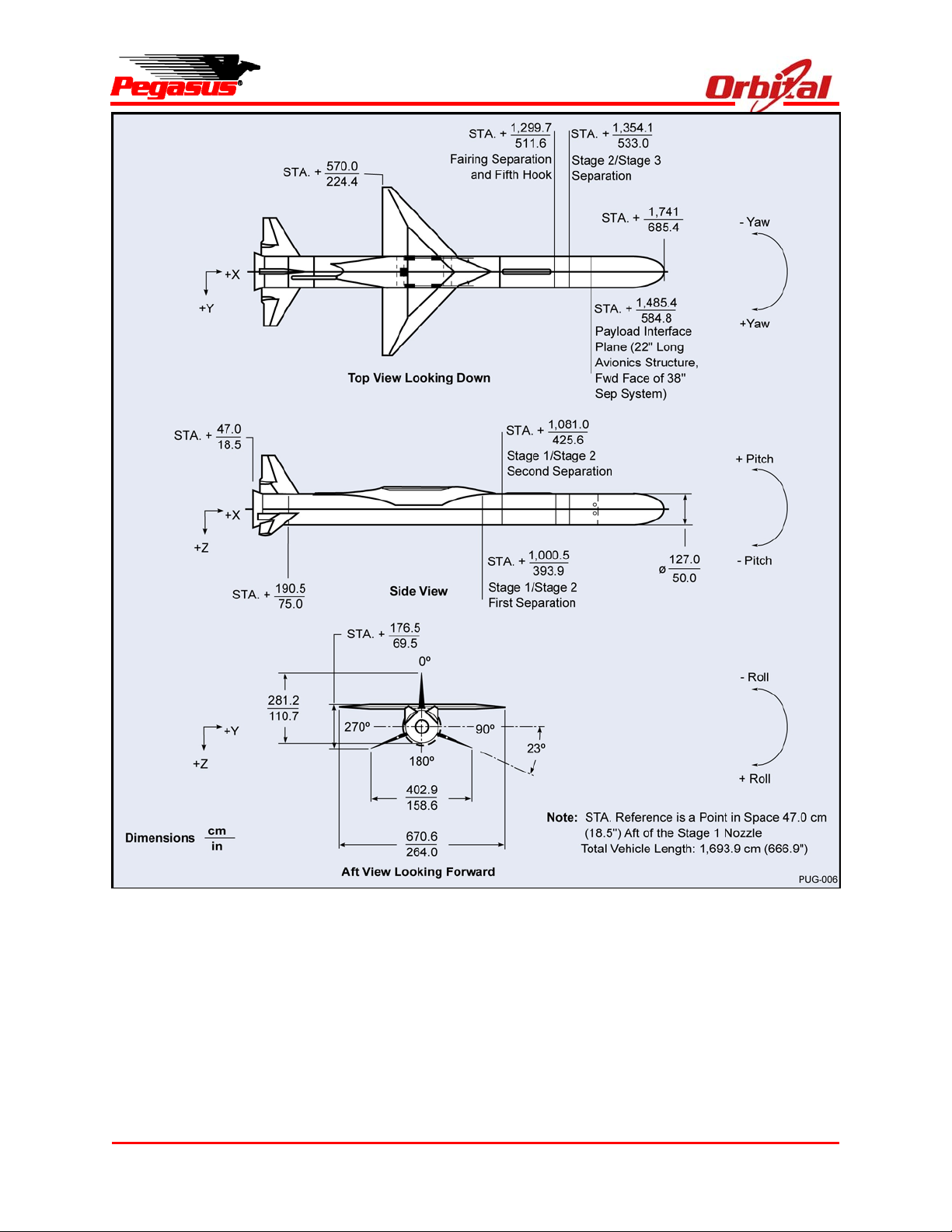
Figure 2-3. Principle Dimensions of Pegasus XL (Reference Only)............................................................ 5
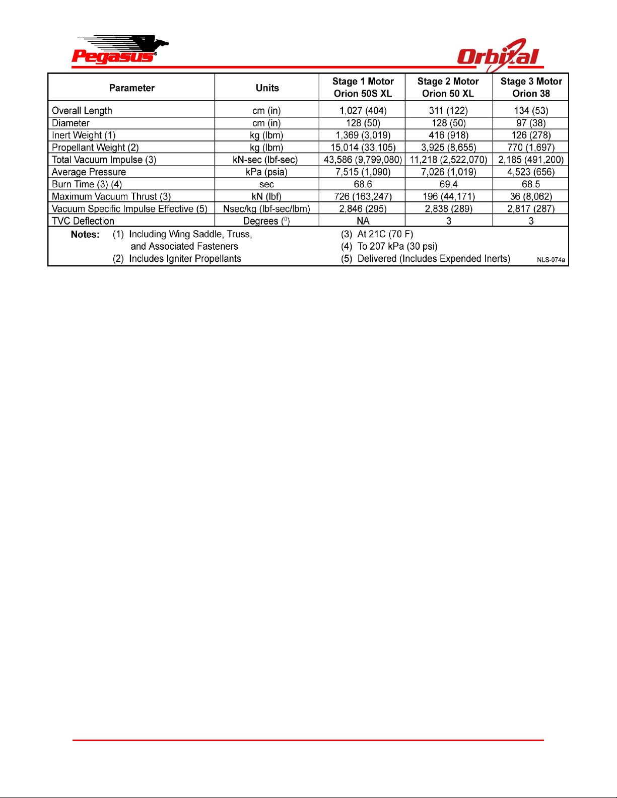
Figure 2-4. Typical Pegasus XL Motor Characteristics in Metric (English) Units ........................................ 6
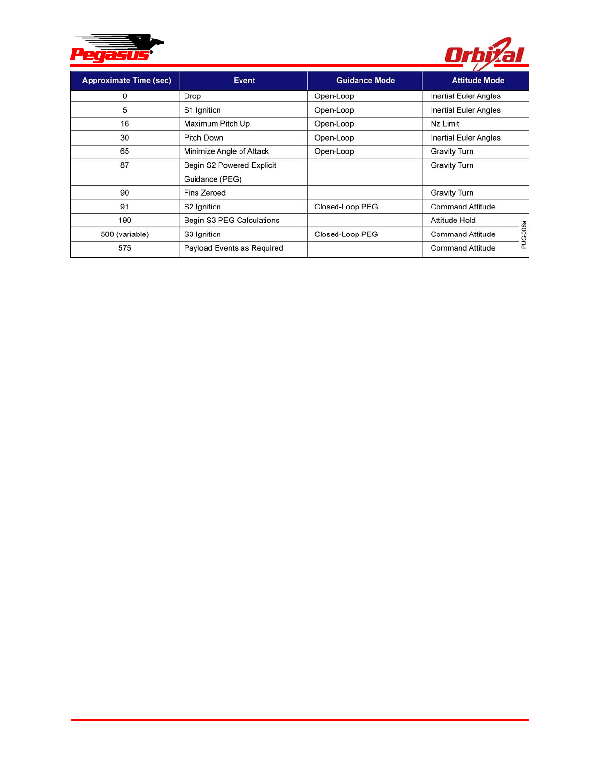
Figure 2-5. Typical Attitude and Guidance Modes Sequence .....................................................................7
Figure 3-1. Pegasus XL Mission Profile to 741 km (400nmi) Circular, Polar Orbit with a 227 kg
(501 lbm) Payload ..................................................................................................................... 9
Figure 3-2. Pegasus XL with HAPS Mission Profile to 741 km (400nmi) Circular, Polar Orbit with
a 227 kg (501 lbm) Payload..................................................................................................... 10
Figure 3-3. Pegasus XL Without HAPS Performance Capability............................................................... 11
Figure 3-4. Pegasus XL With HAPS Performance Capability.................................................................... 12
Figure 3-5. 3-sigma Injection Accuracies Typical of Pegasus XL Missions............................................... 12
Figure 3-6. Typical and Recent Pegasus Orbital Accuracy ....................................................................... 13
Figure 4-1. Factors of Safety for Payload Design and Test....................................................................... 15
Figure 4-2. Payload Testing Requirements ...............................................................................................15
Figure 4-3. Pegasus Design Limit Load Factors........................................................................................ 16
Figure 4-4. Pegasus XL Maximum Quasi Steady Acceleration as a Function of Payload Weight............ 17
Figure 4-5. Pegasus Net CG Load Factor Predictions .............................................................................. 17
Figure 4-6. Motor Ignition Transient Shock Response Spectrum Specification ........................................ 18
Figure 4-7. Payload Interface Random Vibration Specification ................................................................. 18
Figure 4-8. Shock Environment at Base of the Payload ............................................................................ 19
Figure 4-9. Payload Acoustic Environment................................................................................................ 19
Figure 4-10. Representative Fairing Internal Pressure Profile During Captive Carry................................ 20
Figure 4-11. Representative Fairing Internal Pressure Profile During Powered Flight.............................. 20
Figure 4-12. Pegasus XL RF Emitters and Receivers ............................................................................... 22
Figure 4-13. Carrier Aircraft RF Emitters and Receivers ........................................................................... 22
Figure 5-1. Payload Fairing Static Envelope with 97 cm (38 in.) Diameter Payload ................................. 25
Figure 5-2. Payload Fairing Dynamic Envelope with 97 cm (38 in.) Diameter Payload ............................ 26
Figure 5-3. Payload Fairing Static Envelope with 59 cm (23 in.) Diameter Payload ................................. 27
Figure 5-4. Payload Fairing Dynamic Envelope with 59 cm (23 in.) Diameter Payload ............................ 28
Figure 5-5. Payload Fairing Access Door Placement Zones (shown with optional second door shown) . 29
Figure 5-6. Nonseparable Payload Mechanical Interface..........................................................................30
Figure 5-7. 97 cm (38 in.) Separable Payload Interface ............................................................................ 31
Release 7.0 Apr 2010 viii
Page 9

Pegasus User’s Guide
LIST OF FIGURES (CONTINUED)
PAGE
Figure 5-8. 59 cm (23 in.) Separable Payload Interface ............................................................................ 32
Figure 5-9. Payload Separation Velocities Using the Standard Separation System ................................. 33
Figure 5-10. Standard Payload Electrical Interface ................................................................................... 34
Figure 5-11. Payload Mass vs. c.g. Location on X Axis............................................................................. 36
Figure 5-12. Payload Mass Property Measurement Error Tolerances ...................................................... 37
Figure 5-13. Detailed RCS Dead Band Zone............................................................................................. 37
Figure 5-14. Pegasus/OCA Interface Details............................................................................................. 38
Figure 6-1. Mission Integration Management Structure............................................................................. 40
Figure 6-2. Summary of Typical Working Groups...................................................................................... 42
Figure 6-3. Typical Mission Cycle .............................................................................................................. 44
Figure 6-4. Applicable Safety Requirements ............................................................................................. 44
Figure 6-5. Safety Approval Process ......................................................................................................... 46
Figure 7-1. Typical Processing Flow.......................................................................................................... 47
Figure 7-2. Typical Pegasus Integration and Test Schedule ..................................................................... 48
Figure 7-3. Orbital Carrier Aircraft Hot Pad Area at VAFB ........................................................................ 48
Figure 7-4. Pegasus Integration................................................................................................................. 49
Figure 7-5. Typical Pegasus Launch Checklist Flow ................................................................................. 52
Figure 8-1. Documentation Produced by Orbital for Commercial Pegasus Launch Services ................... 53
Figure 8-2. Documentation Required by Orbital for Commercial Pegasus Launch Services.................... 54
Figure 9-1. Load-Bearing Spacecraft Configuration .................................................................................. 57
Figure 9-2. Dual Payload Attach Fitting Configuration............................................................................... 58
Figure 10-1. Hydrazine Auxillary Propulsion System (HAPS) ................................................................... 62
LIST OF APPENDICES
A. PAYLOAD QUESTIONNAIRE..............................................................................................................A-1
B. VAFB VEHICLE ASSEMBLY BUILDING CAPABILITIES ....................................................................B-1
C. LAUNCH RANGE INFORMATION...................................................................................................... C-1
D. PEGASUS FLIGHT HISTORY ............................................................................................................ D-1
Release 7.0 Apr 2010 ix
Page 10

Pegasus User’s Guide
LIST OF ACRONYMS
3DOF Three Degrees of Freedom
6DOF Six Degrees of Freedom
A, Amps Amperes
AACS Airborne Air Conditioning System
ac Alternating Current
A/C Air Conditioning
AFB Air Force Base
AIT Assembly and Integration Trailer
ARAR Accident Risk Asessment Report
ARO After Receipt of Order
ASE Airborne Support Equipment
ATP Authority to Proceed
AWG American Wire Gauge
C/CAM Collision/Contamination Avoidance
Maneuver
C Centigrade
CCB Configuration Control Board
CDR Critical Design Review
CFR Code of Federal Regulations
c.g. Center of Gravity
c.m. Center of Mass
cm Centimeter
dB Decibels
dc Direct Current
deg Degrees
DoD Department of Defense
DoT Department of Transportation
DPA Dual Payload Adapter
DPDT Double Pole, Double Throw
EGSE Electrical Ground Support Equipment
EICD Electrical Interface Control Document
EMC Electromagnetic Compatibility
EME Electromagnetic Environment
EMI Electromagnetic Interference
ER Eastern Range (USAF)
F Fahrenheit
FAA Federal Aviation Administration
FAR Federal Acquisition Regulation
FAS Fin Actuation System
fps Feet Per Second
FRR Flight Readiness Review
ft Feet
FTS Flight Termination System
g Gravity
GCL Guidance and Control Lab
GN2 Gaseous Nitrogen
GN&C Guidance, Navigation, and Control
GOP Ground Operations Plan
GPS Global Positioning System (NAVSTAR)
Grms Gravity Root Mean Squared
GSE Ground Support Equipment
H/W Hardware
h Height
HAPS Hydrazine Auxiliary Propulsion System
HEPA High Efficiency Particulate Air
HF High Frequency
HVAC Heating, Ventilating, and Air
Conditioning
Hz Hertz
ICD Interface Control Document
IEEE Institute of Electrical and Electronic
Engineers
ILC Initial Launch Capability
IMU Inertial Measurement Unit
in. Inch
INS Inertial Navigation System
ISO International Standardization
Organization
kbps Kilobits per Second
kg Kilograms
km Kilometers
KMR Kwajalein Missile Range
kPa Kilo Pascal
L- Time Prior to Launch
L+ Time After Launch
lbf Pound(s) of Force
lbm Pound(s) of Mass
LOWG Launch Operations Working Group
LPO Launch Panel Operator
LRR Launch Readiness Review
LSC Linear Shaped Charge
m/s Meters Per Second
m Meters
M Mach
mA Milliamps
MDL Mission Data Load
MHz MegaHertz
MICD Mechanical Interface Control Document
MIL-STD Military Standard
MIWG Mission Integration Working Group
mm Millimeter
MPS Mission Planning Schedule
MRR Mission Readiness Review
ms Millisecond
MSD Mission Specification Document
MSPSP Missile System Prelaunch Safety
Package
MUX Multiplexer
N2 Nitrogen
N/A Not Applicable
N Newtons
Release 7.0 Apr 2010 x
Page 11

NASA National Aeronautics and Space
Administration
NRTSim Non-Real-Time Simulation
nm Nautical Miles
NTE Not To Exceed
OASPL Overall Sound Pressure Level
OCA Orbital Carrier Aircraft
OD Operations Directive
OR Operations Requirements Document
Orbital Orbital Sciences Corporation
P/L Payload
PA Payload Adapter
PDR Preliminary Design Review
PDU Pyrotechnic Driver Unit
PLF Payload Fairing
POST Program to Optimize Simulated
Trajectories
PPWR P Power
PRD Program Requirements Document
psf Pounds Per Square Foot
psi Pounds Per Square Inch
psig Pounds per Square Inch Gauge
PSP Program Support Plan
PSSTU Pegasus Separation System Test Unit
PTRN P Turn
PTS Power Transfer Switch
PWP Pegasus Work Package
QA Quality Assurance
RCS Reaction Control System
RF Radio Frequency
Pegasus User’s Guide
rpm Revolutions Per Minute
RTB Return to Base
RSS Root Summed Squared
RTV Room Temperature Vulcanizing
S&A Safe & Arm
S/N Serial Number
S/W Software
scfm Standard Cubic Feet Per Minute
sec Second(s)
SSPP System Safety Program Plan
SWC Soft Wall Cleanroom
TLM Telemetry
T.O. Take-Off
TPS Thermal Protection System
TT&C Telemetry, Tracking & Commanding
TVC Thrust Vector Control
UDS Universal Documentation System
UFS Ultimate Factory of Safety
USAF United States Air Force
V Volts
VAB Vehicle Assembly Building
VAFB Vandenberg Air Force Base
VDC Volts Direct Current
VHF Very High Frequency
VSWR Voltage Standing Wave Ratio
VT Verification Test
WFF Wallops Flight Facility
WR Western Range (USAF)
XL Extended Length (Pegasus)
YFS Yield Factor of Safety
Release 7.0 Apr 2010 xi
Page 12
1. INTRODUCTION
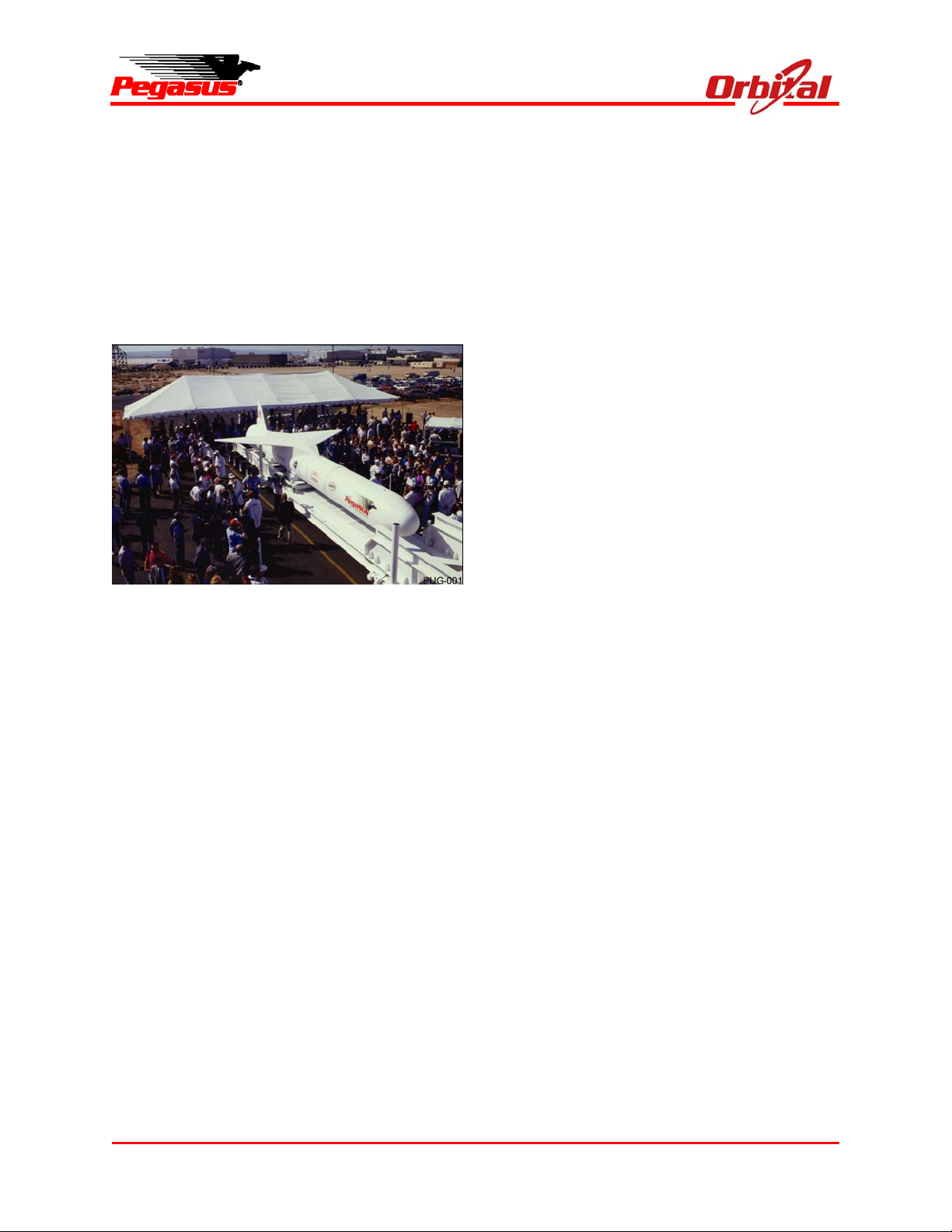
On August 10, 1989, Orbital Sciences Corporation
(Orbital) rolled out the first commercially
developed space launch vehicle for providing
satellites to low earth orbit (see Figure 1-1). Over
the past 21 years, the “winged rocket” known as
Pegasus has proven to be the most successful in
its class, placing over 78 satellites in orbit with 40
launches as of April 2010.
Figure 1-1. Pegasus Rollout
This Pegasus User’s Guide is intended to
familiarize mission planners with the capabilities
and services provided with a Pegasus launch.
The Pegasus XL was developed as an increased
performance design evolution from the original
Pegasus vehicle to support NASA and the USAF
performance requirements, and is now the
baseline configuration for all commercial Pegasus
launches.
Pegasus is a mature and flight-proven launch
system that has demonstrated consistent accuracy
and dependable performance. The Pegasus
launch system has achieved a high degree of
reliability through its significant flight experience.
Pegasus offers a variety of capabilities that are
uniquely suited to small spacecraft. These
capabilities and features provide the small
Pegasus User’s Guide
spacecraft customer with greater mission utility in
the form of:
A range of custom payload interfaces and
services to accommodate unique small
spacecraft missions;
Payload support services at the Pegasus
Vehicle Assembly Building (VAB) at
Vandenberg Air Force Base (VAFB),
California;
Horizontal payload integration;
Shared payload launch accommodations for
more cost-effective access to space as
compared to Dual Launches;
Portable air-launch capability from worldwide
locations to satisfy unique mission
requirements; and
Fast, cost-effective, and reliable access to
space.
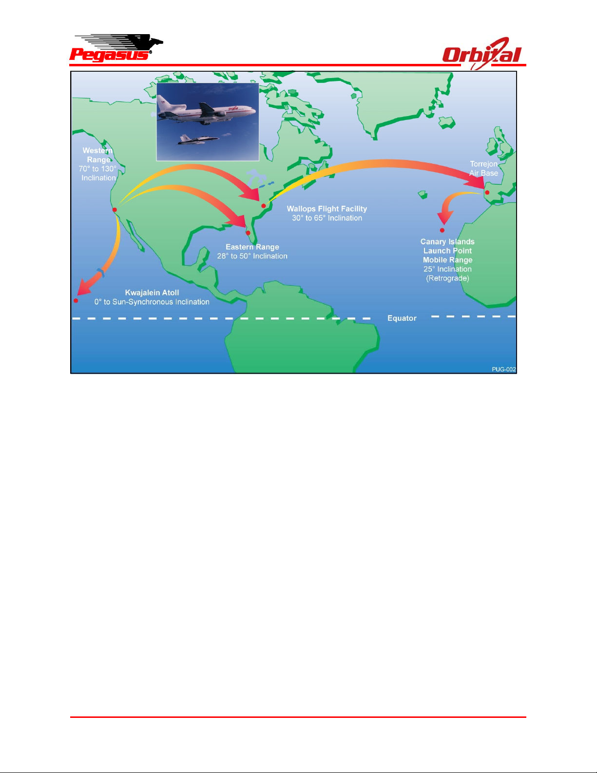
The mobile nature of Pegasus allows Orbital to
integrate the spacecraft to the Pegasus XL in our
integration facility, the VAB, and ferry the launchready system to a variety of launch ranges.
Pegasus has launched from a number of launch
locations worldwide (see Figure 1-2).
The unique mobile capability of the Pegasus
launch system provides flexibility and versatility to
the payload customer. The Pegasus launch
vehicle can accommodate integration of the
spacecraft at a customer desired location, as well
as optimize desired orbit requirements based on
the initial launch location. In 1997, after final build
up of the rocket at the VAB, Pegasus was mated
to the Orbital Carrier Aircraft (OCA) and ferried to
Madrid, Spain, to integrate Spain’s MINISAT-01
satellite. Following integration of the satellite,
Pegasus was then ferried to the island of Gran
Canaria for launch. The successful launch of
Spain’s MINISAT-01 satellite demonstrated
Pegasus’ ability to accommodate the payload
provider’s processing and launch requirements at
locations better suited to the customer rather than
the launch vehicle. This unprecedented launch
Release 7.0 Apr 2010 1
Page 13
Pegasus User’s Guide
Figure 1-2. Pegasus Launch Locations
vehicle approach is an example of the Pegasus
way of providing customer oriented launch service.
In the interest of continued process improvement
and customer satisfaction, the Pegasus Program
successfully completed a 1-year effort of ISO 9001
certification. In July 1998, Orbital’s Launch
Systems Group was awarded this internationally
recognized industry benchmark for operating a
quality management system producing a
qualityproduct and service. Since that time,
Orbital has achieved third party certification to
ISO9001:2008 and AS9100B, providing even
greater assurance of mission success. In addition
to our AS9100B certification, NASA has granted
the Pegasus XL Launch Vehicle a Category 3
certification that qualifies Pegasus to launch
NASA’s highest value spacecraft.
Pegasus is a customer oriented and responsive
launch vehicle system. From Pegasus’ com-
mercial heritage comes the desire to continually
address the payload customer market to best
accommodate its needs. The Pegasus launch
vehicle system has continually matured and
evolved over its 21-year history. This ability and
desire to react to the customer has produced the
single most successful launch vehicle in its class.
To ensure our goal of complete customer
satisfaction, a team of managers and engineers is
assigned to each mission from “contract award to
post-flight report.” This dedicated team is
committed to providing the payload customer
100% satisfaction of mission requirements.
Each Pegasus mission is assigned a mission team
led by a Mission Manager and a Mission Engineer.
The mission team is responsible for mission
planning and scheduling, launch vehicle
production coordination, payload integration
services, systems engineering, mission-peculiar
design and analysis, payload interface definition,
Release 7.0 Apr 2010 2
Page 14
range coordination, launch site processing, and
operations. The mission team is responsible for
ensuring all mission requirements have been
satisfied.
2. PEGASUS DESCRIPTION
The Pegasus User’s Guide is dedicated to the
discussion of the Pegasus XL configuration,
capabilities, and associated services.
2.1. Pegasus XL Vehicle Description
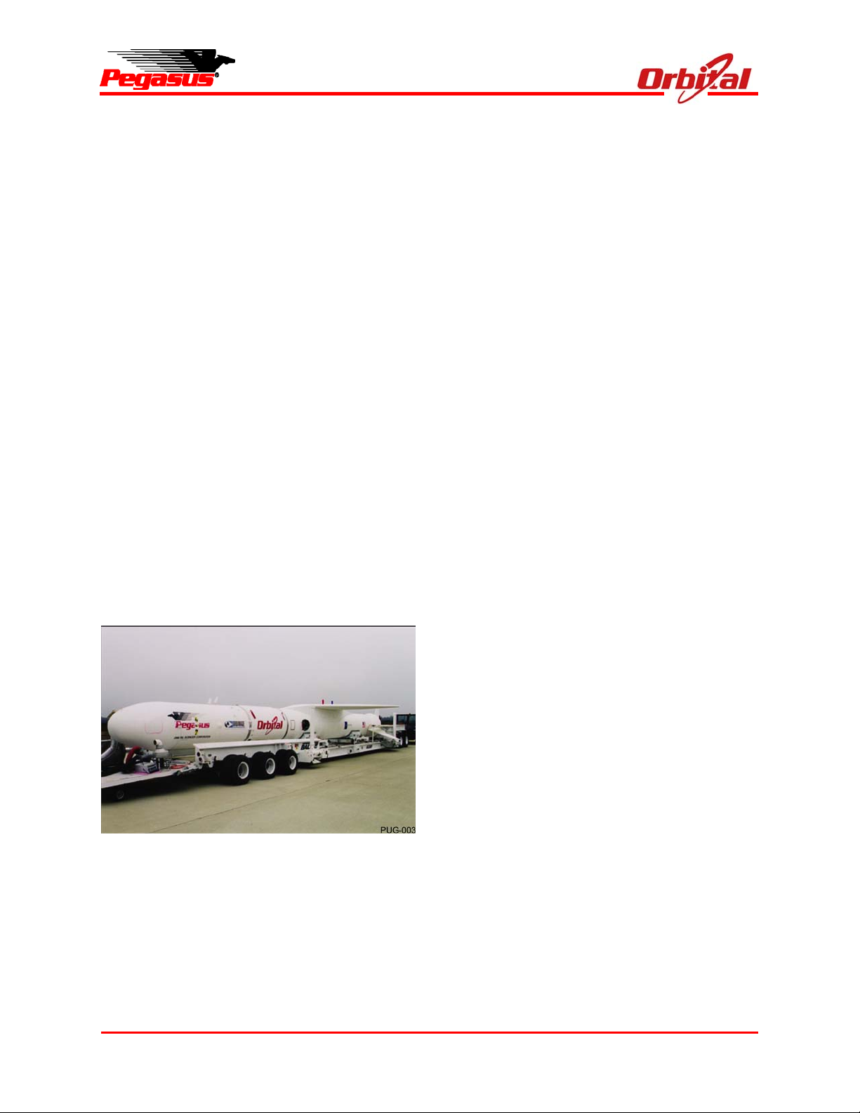
Pegasus XL is a winged, three-stage, solid rocket
booster that weighs approximately 23,130 kg
(51,000 lbm), and measures 16.9 m (55.4 ft) in
length and 1.27 m (50 in.) in diameter, and has a
wing span of 6.7 m (22 ft). Figure 2-1 shows the
Pegasus on the Assembly Integration Trailer (AIT).
Pegasus is lifted by the OCA to a level flight
condition of about 11,900 m (39,000 ft) and Mach
0.82. Five seconds after release from the OCA
Stage 1 motor ignition occurs. The vehicle’s
autonomous guidance and flight control system
provide the guidance necessary to insert payloads
into a wide range of orbits.
Figure 2-1. Pegasus XL on the Assembly and
Integration Trailer (AIT)
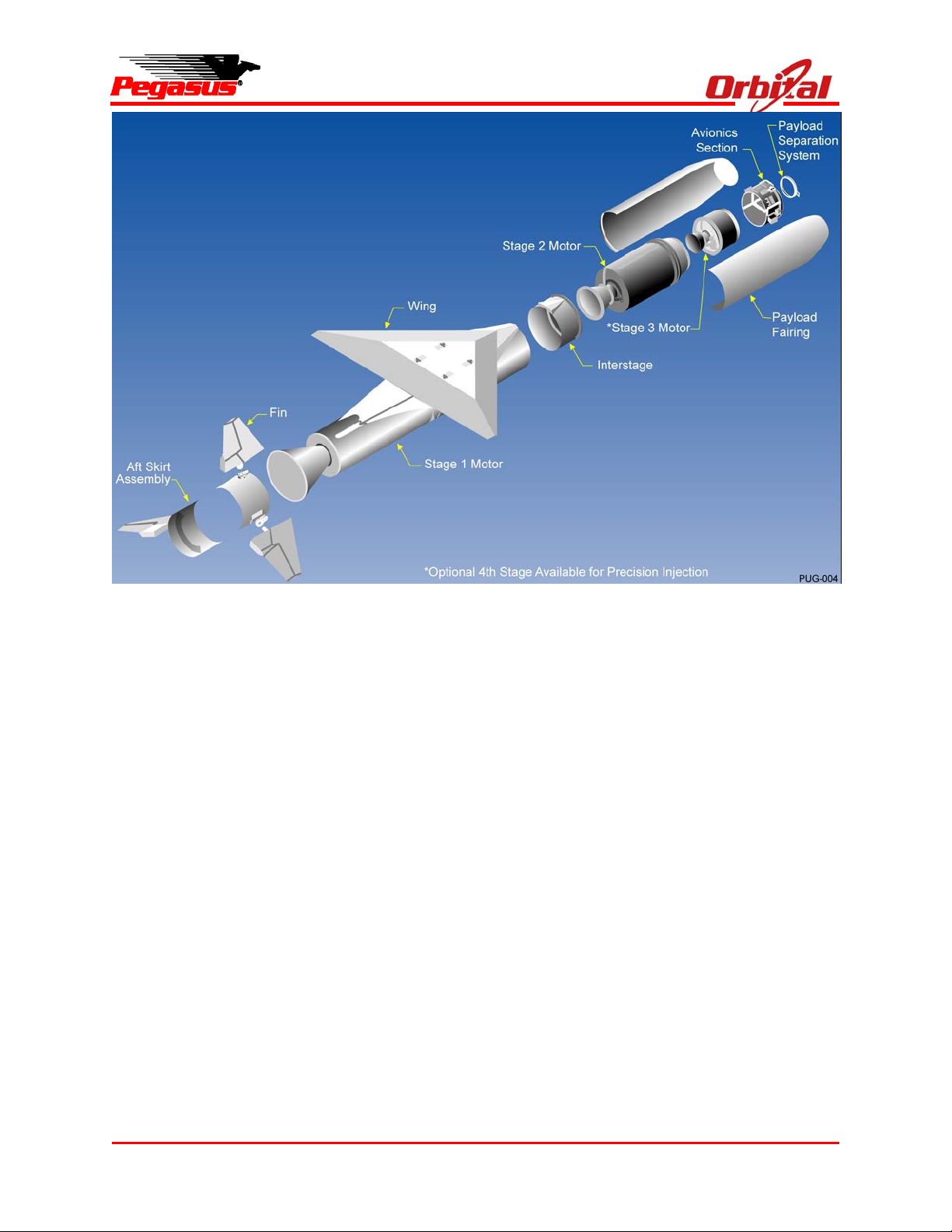
Figure 2-2 shows an expanded view of the
Pegasus XL configuration. The Pegasus Vehicle
design combines flight-proven technologies, and
conservative design margins to achieve
performance and reliability. The vehicle
incorporates eight major elements:
Pegasus User’s Guide
Three solid rocket motors;
A payload fairing;
An avionics assembly;
A lifting wing;
Aft skirt assembly including three movable
control fins; and
A payload interface system.
Pegasus also has an option for a liquid propellant
fourth stage, HAPS (see Section 10). Figure 2-3
illustrates Pegasus XL’s principle dimensions.
2.1.1. Solid Rocket Motors
The three solid rocket motors were designed and
optimized specifically for Pegasus and include
features that emphasize reliability and
manufacturability. The design was developed
using previously flight-proven and qualified
materials and components. Common design
features, materials, and production techniques are
applied to all three motors to maximize cost
efficiency and reliability. These motors are fully
flight-qualified. Typical motor characteristics are
shown in Figure 2-4.
2.1.2. Payload Fairing
The Pegasus payload fairing consists of two
composite shell halves, a nose cap integral to a
shell half, and a separation system. Each shell
half is composed of a cylinder and ogive sections.
The two halves are held together with a base
frangible joint, two titanium straps along the
cylinder and a retention bolt in the nose. A cork
and Room Temperature Vulcanizing (RTV)
Thermal Protection System (TPS) provides
protection to the graphite composite fairing
structure. The amount of TPS applied has been
determined to optimize fairing performance and
payload environmental protection.
The two straps are tensioned using bolts, which
are severed during fairing separation with
pyrotechnic bolt cutters, while the retention bolt in
the nose is released with a pyrotechnic separation
nut. The base of the fairing is separated with
Release 7.0 Apr 2010 3
Page 15
Pegasus User’s Guide
Figure 2-2. Expanded View of Pegasus XL Configuration
Orbital’s low-contamination frangible separation
joint. These ordnance events are sequenced for
proper separation dynamics. A hot gas generator
internal to the fairing is also activated at
separation to pressurize two piston-driven pushoff
thrusters. These units, in conjunction with cams,
force the two fairing halves apart. The halves
rotate about fall-away hinges, which guide them
away from the satellite and launch vehicle.
The fairing and separation system were fully
qualified through a series of structural, functional,
and contamination ground vacuum tests and have
been successfully flown on all Pegasus XL
missions. Section 5 presents a more detailed
description of the fairing separation sequence and
the satellite dynamic envelope.
2.1.3. Avionics
The Pegasus avionics system is a digital
distributed processor design that implements
developments in hardware, software, communi-
cations, and systems design. Mission reliability is
achieved by the use of simple designs, high
reliability components, high design margins, and
extensive testing at the component, subsystem,
and system level.
The heart of the Pegasus avionics system is a
multiprocessor, 32-bit flight computer. The flight
computer communicates with the Inertial
Measurement Unit (IMU), the launch panel
electronics on the carrier aircraft, and all vehicle
subsystems using standard RS-422 digital serial
data links. Most avionics on the vehicle feature
integral microprocessors to perform local
processing and to handle communications with the
flight computer. This RS-422 architecture is
central to Pegasus rapid integration and test, as it
allows unit and system-level testing to be
accomplished using commercially available
ground support equipment with off-the-shelf
hardware.
Release 7.0 Apr 2010 4
Page 16
Pegasus User’s Guide
Figure 2-3. Principle Dimensions of Pegasus XL (Reference Only)
2.1.4. Flight Termination System
The Pegasus Flight Termination System (FTS)
supports ground-initiated command destruct as
well as the capability to sense inadvertent stage
separation and automatically destruct the rocket.
The FTS is redundant, with two independent safe
and arm devices, receivers, logic units, and
batteries.
2.1.5. Attitude Control Systems
After release from the OCA, the Pegasus attitude
control system is fully autonomous. A combination
of open-loop steering and closed-loop guidance is
employed during the flight. Stage 1 guidance
utilizes a pitch profile optimized by ground
simulations. Stage 2 and Stage 3 guidance uses
an adaptation of an algorithm that was first
Release 7.0 Apr 2010 5
Page 17
Pegasus User’s Guide
Figure 2-4. Typical Pegasus XL Motor Characteristics in Metric (English) Units
developed for the Space Shuttle ascent guidance.
Attitude control is closed-loop.
The vehicle attitude is controlled by the Fin
Actuator System (FAS) during Stage 1 flight. This
consists of electrically actuated fins located at the
aft end of Stage 1. For Stage 2 and Stage 3 flight,
a combination of electrically activated Thrust
Vector Controllers (TVCs) on the Stage 2 and
Stage 3 solid motor nozzles and a GN2 Reaction
Control System (RCS) located on the avionics
section, control the vehicle attitude.
Figure 2-5 summarizes the attitude and guidance
modes during a typical flight, although the exact
sequence is controlled by the Mission Data Load
(MDL) software and depends on mission-specific
requirements.
2.1.6. Telemetry Subsystem
The Pegasus XL telemetry system provides realtime health and status data of the vehicle avionics
system, as well as key information regarding the
position, performance, and environment of the
Pegasus XL vehicle. This data is used by Orbital
and the range safety personnel to evaluate system
performance.
Pegasus contains two separate telemetry
systems. The first provides digital data through
telemetry multiplexers (MUXs), which gather data
from each sensor, digitize it, then relay the
information to the flight computer. This Pegasus
telemetry stream provides data during ground
processing, checkout, captive carry, and during
launch. During captive carry, Pegasus telemetry
is downlinked to the ground and recorded onboard
the OCA. Some payload telemetry data can be
interleaved with Pegasus data as a nonstandard
service. The second system provides analog
environments data, which are transmitted via a
wideband data link and recorded for post-flight
evaluation.
2.1.7. Major Structural Subsystems
2.1.7.1. Wing
The Pegasus wing uses a truncated delta platform
with a double wedge profile. Wing panels are
made of a graphite-faced foam sandwich.
Channel section graphite spars carry the primary
bending loads and half-ribs, and reinforcing layups further stabilize the panels and reduce stress
concentrations. The wing central box structure
has fittings at each corner that provide the
structural interface between the Pegasus and the
OCA.
Release 7.0 Apr 2010 6
Page 18
Pegasus User’s Guide
Figure 2-5. Typical Attitude and Guidance Modes Sequence
2.1.7.2. Aft Skirt Assembly
The aft skirt assembly is composed of the aft skirt,
three fins, and the fin actuator subsystem. The aft
skirt is an all-aluminum structure of conventional
ring and stressed-skin design with machined
bridge fittings for installation of the
electromechanical fin actuators. The skirt is
segmented to allow installation around the first
stage nozzle. Fin construction is a one-piece solid
foam core and wet-laid graphite composite
construction around a central titanium shaft.
2.1.7.3. Payload Interface Systems
Multiple mechanical and electrical interface
systems currently exist to accommodate a variety
of spacecraft designs. Section 5.0 describes
these interface systems. To ensure optimization
of spacecraft requirements, payload specific
mechanical and electrical interface systems can
be provided to the payload customer. Payload
mechanical fit checks and electrical interface
testing with these spacecraft unique interface
systems are encouraged to ensure all spacecraft
requirements are satisfied early in the processing
flow.
2.2. Orbital Carrier Aircraft
Orbital furnishes and operates the OCA. After
integration at Orbital’s West Coast integration site
at VAFB, the OCA can provide polar and high-
inclination launches utilizing the tracking,
telemetry, and command (TT&C) facilities of the
WR. The OCA can provide lower inclination
missions from the East Coast using either the
NASA or ER TT&C facilities or from the Reagan
Test Site from the Kwajalein Atoll, as well as
equatorial missions from the Kwajalein Atoll. The
OCA is made available for mission support on a
priority basis during the contract-specified launch
window.
The unique OCA-Pegasus launch system
accommodates two distinctly different launch
processing and operations approaches for nonVAFB launches. One approach (used by the
majority of payload customers) is to integrate the
Pegasus and payload at the VAB and then ferry
the integrated Pegasus and payload to another
location for launch. This approach is referred to
as a “ferry mission.” The second approach is
referred to as a “campaign mission.” A campaign
mission starts with the build up of the Pegasus at
the VAB. The Pegasus is then mated to the OCA
at VAFB and ferried to the integration site where
the Pegasus and payload are fully integrated and
tested. At this point, the launch may either occur
at the integration site, or the integrated Pegasus
and payload may be ferried to another location for
launch.
Release 7.0 Apr 2010 7
Page 19

The OCA also has the capability to ferry Pegasus
across the United States or across the ocean
(depending on landing site) to support ferry and
campaign missions.
3. GENERAL PERFORMANCE CAPABILITY
This section describes the orbital performance
capabilities of the Pegasus XL vehicle with and
without the optional HAPS described in Section
10. Together these configurations can deliver
payloads to a wide variety of circular and elliptical
orbits and trajectories, and attain a complete
range of prograde and retrograde inclinations
through a suitable choice of launch points and
azimuths. In general, the optional HAPS will
provide additional performance at higher altitudes,
as well as providing a more accurate insertion
orbit capability.
From the WR, Pegasus can achieve inclinations
between 70° and 130°. A broader range of
inclinations may be achievable, subject to
additional analyses and coordination with Range
authorities. Additionally, lower inclinations can be
achieved through dog-leg trajectories, with a
commensurate reduction in performance. Some
specific inclinations within this range may be
limited by stage impact point or other restrictions.
Other inclinations can be supported through use of
Wallops Flight Facility (WFF), Eastern Range
(ER), Reagan Test Site (RTS) Kwajalein, or other
remote TT&C sites. Pegasus requirements for
remote sites are listed in Appendix D.
3.1. Mission Profiles
This section describes circular low earth orbit
mission profiles. Performance quotes for noncircular orbits will be provided on a missionspecific basis.
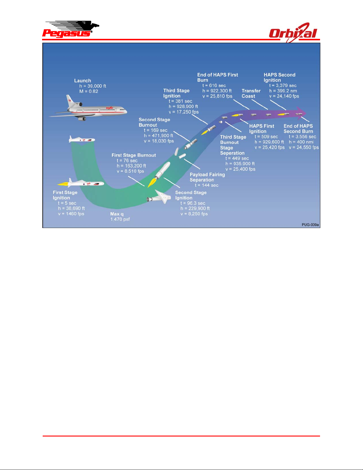
Profiles of typical missions performed by Pegasus
XL with and without HAPS are illustrated in
Figure 3-1 and Figure 3-2. The depicted profile
begins after the OCA has reached the launch
Pegasus User’s Guide
point, and continues through orbit insertion. The
time, altitude, and velocity for the major ignition,
separation, and burnout events are shown for a
typical trajectory that achieves a 741 km (400 nm)
circular, polar (90° inclination) orbit after launch
from the WR. These events will vary based on
mission requirements.
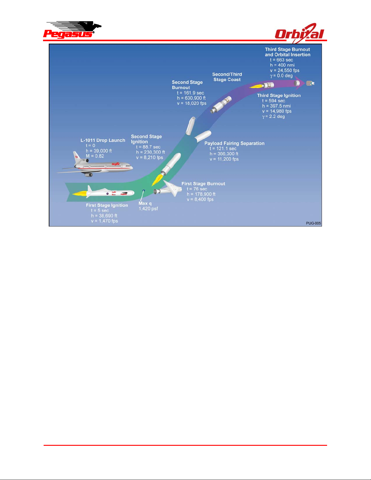
The typical launch sequence begins with release
of Pegasus from the carrier aircraft at an altitude
of approximately 11,900 m (39,000 ft) and a speed
of Mach 0.82. Approximately 5 seconds after
drop, when Pegasus has cleared the aircraft,
Stage 1 ignition occurs. The vehicle quickly
accelerates to supersonic speed while beginning a
pull up maneuver. Maximum dynamic pressure is
experienced approximately 30 seconds after
ignition. At approximately 15-20 seconds, a
maneuver is initiated to depress the trajectory and
the vehicle transitions to progressively lower
angles of attack.
Stage 2 ignition occurs shortly after Stage 1
burnout, and the payload fairing is jettisoned
during Stage 2 burn as quickly as fairing dynamic
pressure and payload aerodynamic heating
limitations will allow, approximately 112,000 m
(366,000 ft) and 121 seconds after drop. Stage 2
burnout is followed by a long coast, during which
the payload and Stage 3 achieve orbital altitude.
For a non-HAPS Pegasus configuration, Stage 3
then provides the additional velocity necessary to
circularize the orbit. Stage 3 burnout typically
occurs approximately 10 minutes after launch and
2,200 km (1,200 nm) downrange of the launch
point.
An FAS, in conjunction with three aerodynamic
fins, provides attitude control from drop through
Stage 1 separation. Pitch and yaw attitude control
during Stage 2 and Stage 3 powered flight is
provided by the motor TVC system while roll
attitude is controlled by the nitrogen cold gas RCS.
The RCS also provides three-axis control during
coast phases of the trajectory.
Release 7.0 Apr 2010 8
Page 20
Pegasus User’s Guide
Figure 3-1. Pegasus XL Mission Profile to 741 km (400nmi) Circular, Polar Orbit with a 227 kg
(501 lbm) Payload
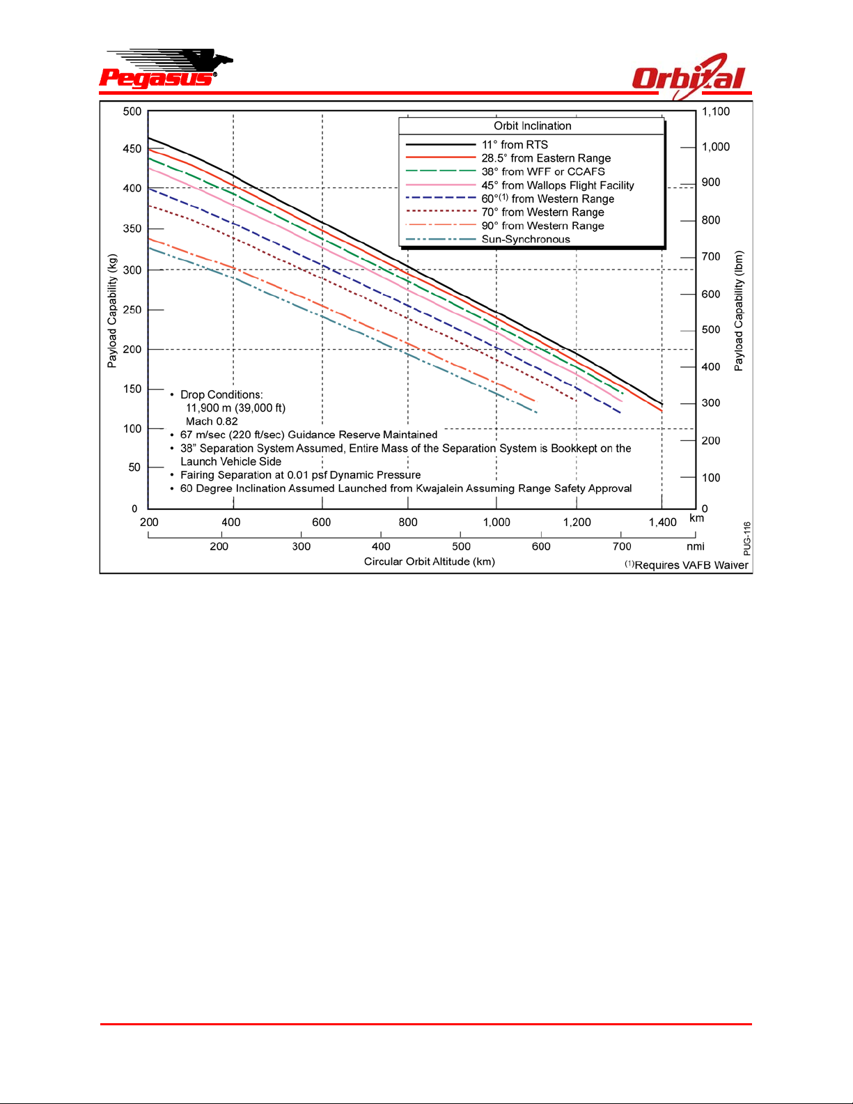
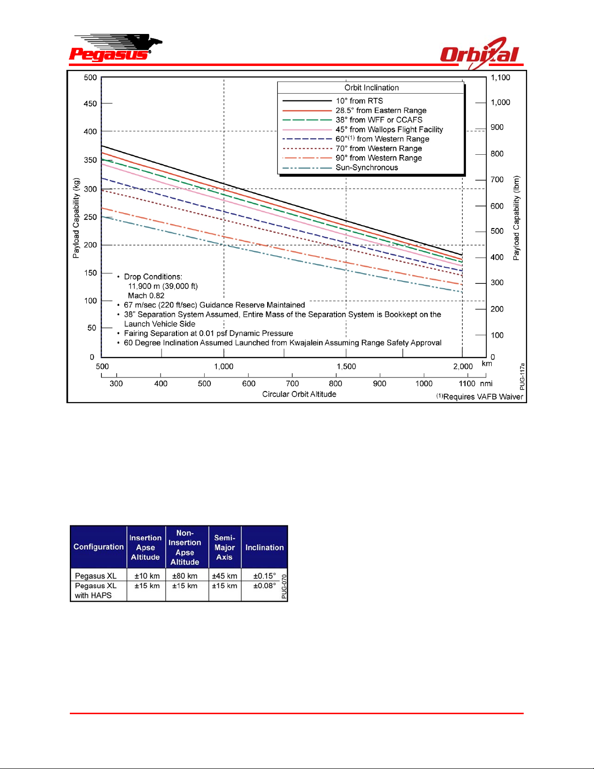
3.2. Performance Capability
Performance capabilities to various orbits for the
Pegasus XL are illustrated in Figure 3-3 and
Figure 3-4 (HAPS configuration). These
performance data were generated using the
Program to Optimize Simulated Trajectories
(POST), which is described below. Precise
performance capabilities to specific orbits are
typically provided per the documentation schedule
shown in Section 8.0.
3.3. Trajectory Design Optimization
Orbital designs a unique mission trajectory for
each Pegasus flight to maximize payload
performance while complying with any applicable
payload and launch vehicle constraints. In this
process, a 3DOF simulation is developed using
the current Pegasus mass properties,
aerodynamic models, and motor ballistics data,
and the desired target orbit and any applicable
trajectory constraints are specified. POST then
uses a set of specified control parameters to
iterate on the trajectory design until an optimal
solution is identified which maximizes performance
to the desired target orbit subject to the specified
constraints. Typically, these constraints may
include limitations on the angle of attack profile,
dynamic loading constraints, payload
environmental constraints such as heat rate, and
Range-imposed constraints on the launch azimuth
and spent stage impact locations. After POST has
been used to determine the optimal trajectory
design, a high-fidelity, Pegasus-specific, 6DOF
simulation is then developed to conduct detailed
trajectory analyses to verify the acceptability of the
trajectory design and to verify robust control
system stability margins.
3.4. Orbit Insertion Accuracy
The estimated orbit insertion errors for Pegasus
vary from mission to mission and are influenced by
a variety of factors including the target orbit,
Release 7.0 Apr 2010 9
Page 21
Pegasus User’s Guide
Figure 3-2. Pegasus XL with HAPS Mission Profile to 741 km (400nmi) Circular, Polar Orbit with a
227 kg (501 lbm) Payload
trajectory design, payload mass, and the guidance
strategy requested by the payload. As a result,
the specific Pegasus orbit accuracy capabilities for
a particular mission are generally determined only
after these mission-specific details are defined and
detailed mission-specific analyses have been
performed. However, Figure 3-5 provides
estimates of 3-sigma orbit insertion errors for both
Pegasus XL and Pegasus XL with HAPS vehicle
configurations, which are representative of typical
Pegasus missions. For non-HAPS configurations,
these errors are generally dominated by the
impulse variability associated with Stage 3. This
variability is also responsible for the generally
larger magnitude errors for the non-insertion apse
relative to the insertion apse.
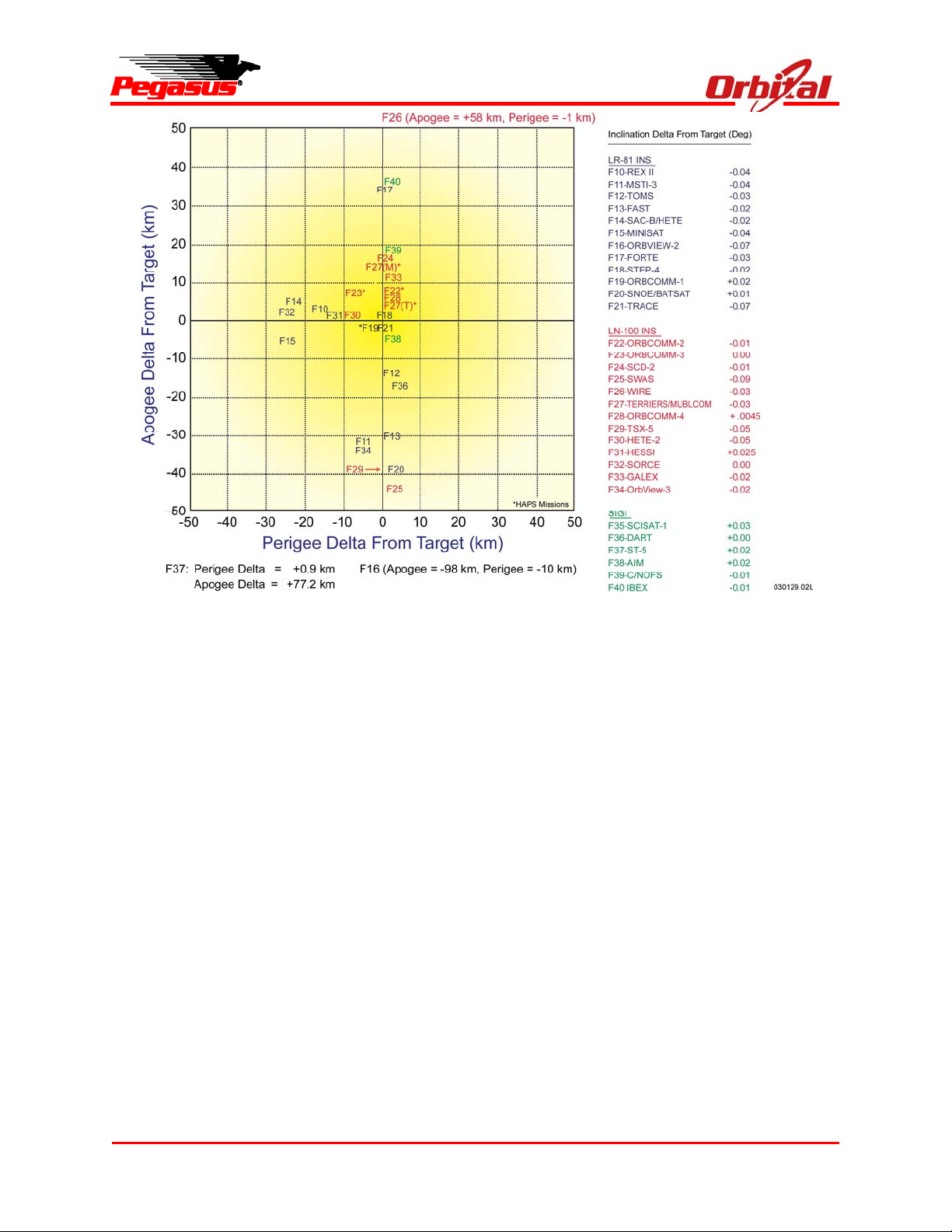
3.4.1. Actual Pegasus Insertion Accuracies
Figure 3-6 shows the actual Pegasus orbital
insertion accuracies achieved for all missions
since Flight 10. As this figure demonstrates, a
large majority of these missions resulted in
perigee and apogee altitudes within 30 km of the
desired target values and inclination errors of less
than 0.05 degrees.
3.4.2. Error-Minimizing Guidance Strategies
Due to the large amount of actual flight experience
Pegasus has accumulated to date, the Pegasus
Program has been able to continually refine and
improve the fidelity and accuracy of the Pegasus
vehicle simulation. This process has allowed us to
develop a high degree of confidence in the
Pegasus simulation analysis results and to
accurately predict mission performance in flight.
To ensure that even a 3-sigma low-performing
Pegasus vehicle will achieve the required orbit,
Pegasus trajectories include a 67 m/sec
(220 ft/sec) guidance reserve. Pegasus flight
software provides the capability to manage this
reserve through the use of a variety of different
Release 7.0 Apr 2010 10
Page 22
Pegasus User’s Guide
Figure 3-3. Pegasus XL Without HAPS Performance Capability
guidance strategies that are designed and tailored
to meet specific mission objectives. These
strategies fall into several basic categories:
(1) Minimize Insertion Errors. Using this strategy,
the guidance system manages the excess
vehicle energy by implementing out-of-plane
turning during Stage 2 and Stage 3 burns as
required, and by adjusting the timing of
Stage 3 ignition. This “energy-scrubbing”
strategy results in the smallest possible
insertion errors for both apogee and perigee
altitudes.
(2) Maximize Insertion Altitude. Using this
strategy, excess vehicle performance is
conserved to maximize the altitude at
insertion. This allows the customer to achieve
the highest possible circular orbit altitude
based on the actual vehicle performance while
minimizing the eccentricity of the final orbit.
(3) Maximize Insertion Velocity. Using this
strategy, excess vehicle performance is
conserved to maximize velocity at insertion.
This allows the customer to use the excess
guidance reserve to increase the expected
apogee (non-insertion apse) altitude while
continuing to maintain a precise perigee
(insertion apse) altitude.
(4) Some Combination of (2) and (3). Options 2
and 3 represent the two endpoints of a
spectrum of potential guidance strategies that
can be combined and tailored to achieve
mission-specific guidance objectives. Both
insertion altitude and velocity may be
maximized to achieve the highest possible
Release 7.0 Apr 2010 11
Page 23
Pegasus User’s Guide
Figure 3-4. Pegasus XL With HAPS Performance Capability
orbit energy, or specific altitude and velocity
thresholds may be defined, which trigger
energy-scrubbing only in the event that the
thresholds are exceeded. The optimal
strategy for a particular mission will therefore
depend on the specific guidance objectives.
Figure 3-5. 3-sigma Injection Accuracies
Typical of Pegasus XL Missions
3.5. Collision/Contamination Avoidance
Maneuver
Following orbit insertion, the Pegasus Stage 3
RCS or HAPS will perform a Collision/Contam-
ination Avoidance Maneuver (C/CAM). The
C/CAM consists of a series of maneuvers
designed to both minimize payload contamination
and the potential for recontact between Pegasus
hardware and the separated payload.
Orbital will perform a recontact analysis for post
separation events. Orbital and the payload
contractor are jointly responsible for determination
of whether a C/CAM is required.
A typical C/CAM (for a non-HAPS configuration)
consists of the following steps:
(1) At payload separation +3 seconds, the launch
vehicle performs a 90° yaw maneuver
designed to direct any remaining Stage 3
motor impulse in a direction that will increase
Release 7.0 Apr 2010 12
Page 24
Pegasus User’s Guide
Figure 3-6. Typical and Recent Pegasus Orbital Accuracy
the separation distance between the two
bodies.
(2) At payload separation +300 seconds, the
launch vehicle begins a “crab-walk” maneuver.
This maneuver, performed through a series of
RCS thruster firings, is designed to impart a
small amount of delta velocity in a direction
designed to increase the separation distance
between Pegasus and the payload. The
maneuver is terminated approximately
600 seconds after separation.
At the completion of the C/CAM, all remaining
nitrogen and/or hydrazine is depleted.
4. PAYLOAD ENVIRONMENTS
The following subsections present the maximum
payload environment levels during Pegasus
captive carry and powered flight. The acoustic,
vibration, shock, and acceleration environments
presented below apply to the launch vehicle with a
single payload using either the 38" or 23" payload
adapter. The payload environments associated
with the use of alternative separation systems, a
nonseparating payload interface, or multiple
payload attach fittings will differ from those
presented below.
The electromagnetic radiation and thermal
environments presented below apply to all launch
vehicle and payload configurations.
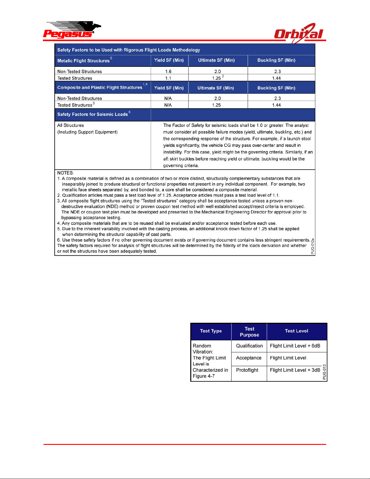
4.1. Design Loads
The primary support structure for the spacecraft
shall possess sufficient strength, rigidity, and other
characteristics required to survive the critical
loading conditions that exist within the envelope of
handling and mission requirements, including
worst-case predicted ground, flight, and orbital
Release 7.0 Apr 2010 13
Page 25

loads. It shall survive those conditions in a
manner that ensures safety and that does not
reduce the mission success probability. The
primary support structure of the spacecraft shall
be electrically conductive to establish a single
point electrical ground. Spacecraft design loads
are defined as follows:
Design Limit Load — The maximum predicted
ground-based, captive carry, or powered flight
load, including all uncertainties.
Design Yield Load — The Design Limit Load
multiplied by the required Yield Factor of
Safety (YFS) indicated in Figure 4-1. The
payload structure must have sufficient strength
to withstand simultaneously the yield loads,
applied temperature, and other accompanying
environmental phenomena for each design
condition without experiencing detrimental
yielding or permanent deformation.
Design Ultimate Load — The Design Limit
Load multiplied by the required Ultimate
Factor of Safety (UFS) indicated in Figure 4-1.
The payload structure must have sufficient
strength to withstand simultaneously the
ultimate loads, applied temperature, and other
accompanying environmental phenomena
without experiencing any fracture or other
failure mode of the structure.
4.2. Payload Testing and Analysis
Sufficient payload testing and/or analysis must be
performed to ensure the safety of ground and
aircraft crews and to ensure mission success. The
payload design must comply with the testing and
design factors of safety in Figure 4-1 and the FAA
regulations for the carrier aircraft listed in the
CFR14 document, FAR Part 25. UFS shown in
Figure 4-1 must be maintained per Orbital SSD
TD-0005. At a minimum, the following tests must
be performed:
Structural Integrity — Static loads or other
tests shall be performed that combine to
encompass the acceleration load environment
presented in Section 4.3. Test level
requirements are defined in Figure 4-1.
Pegasus User’s Guide
Random Vibration — Test level requirements
are defined in Figure 4-2.
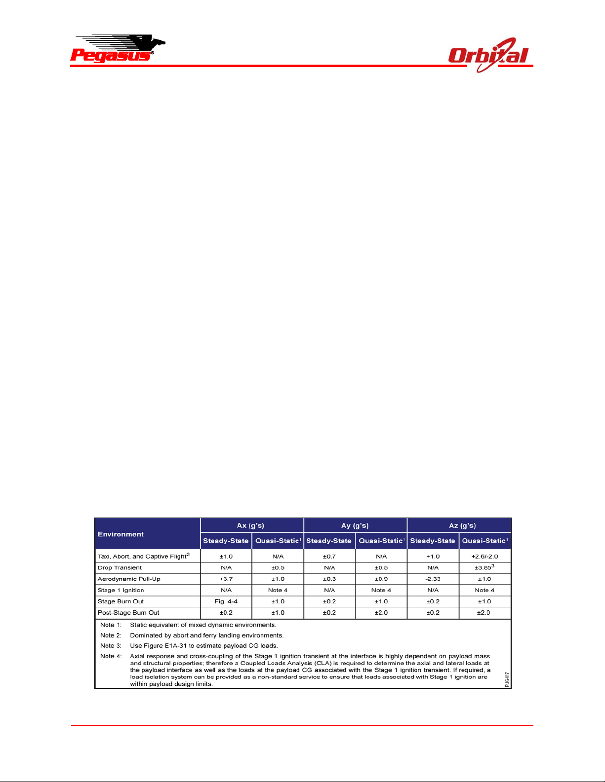
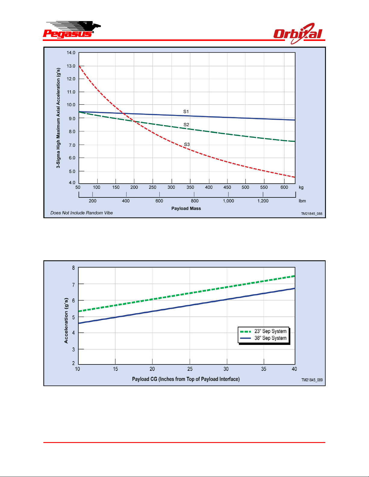
4.3. Payload Acceleration Environment
Maximum expected loads during captive carry and
launch are shown in Figures 4-3, 4-4, and 4-5.
The Pegasus air-launch operation results in a
launch vehicle/OCA separation transient at drop.
The drop transient acceleration limits presented
here are based on two assumptions:
(1) Pegasus Standard 23” or 38” payload
separation system is used.
(2) The first fundamental lateral frequency of the
spacecraft cantilevered at the payload
interface (excluding the payload separation
system) is greater than 20 Hz.
If either assumption is violated, mission-specific
analyses are required. For all missions, accurate
estimation of the drop transient loading requires a
coupled loads analysis (CLA), which uses Orbital
and customer-provided finite element models to
predict the transient environment (see Section
8.3.3 for details).
Transient loading also exists due to motor ignition.
Stage 1 provides the worst-case loading due to
motor ignition. The Stage 1 ignition acceleration
limits at the payload interface are listed in
Figure 4-3. The Stage 1 shock response
spectrum (SRS) at the payload interface is shown
in Figure 4-6. As is the case with the drop
transient, accurate estimation of loading requires a
CLA. The Stage 1 ignition transient CLA requires
finite element models of the Pegasus avionics
structure, payload separation system, and the
payload.
4.4. Payload Random Vibration Environment
The maximum expected random vibration levels at
the payload interface are shown in Figure 4-7.
Random vibration data recorded during multiple
Pegasus missions was used to create this overall
Release 7.0 Apr 2010 14
Page 26
Pegasus User’s Guide
Figure 4-1. Factors of Safety for Payload Design and Test
envelope that encompasses all phases of a
Pegasus launch operation including OCA takeoff,
captive carry, and powered flight.
A +3 dB factor should be added to this spectrum
for 75 seconds in each axis for payload standard
vibration testing to account for fatigue duration
effects to encompass at least two launch attempts
and powered flight.
4.5. Sinusoidal Vibration
The Pegasus launch vehicle has no significant
sustained sinusoidal vibration environments during
captive carry or powered flight.
4.6. Payload Shock Environment
The maximum expected shock response spectrum
at the base of the payload from all launch vehicle
events is shown in Figure 4-8. The flight limit
levels are derived from ground stage and payload
separation test data assuming a 38” Orbitalsupplied separation system.
Figure 4-2. Payload Testing Requirements
4.7. Payload Acoustic Environment
The maximum expected acoustic levels within the
payload fairing are shown in Figure 4-9. Acoustic
data recorded during previous Pegasus missions
Release 7.0 Apr 2010 15
Page 27
Pegasus User’s Guide
was used to create this overall envelope that
encompasses all phases of Pegasus launch
operation including OCA takeoff, captive carry,
and powered flight.
A +6 dB factor should be added to this spectrum
for 75 seconds for payload standard acoustic
testing to account for fatigue duration effects to
encompass at least two launch attempts and
powered flight.
4.8. Pressure Profile
Due to the low pressure decay rate associated
with OCA ascent and low initial static pressure at
drop, the depressurization rates for the Pegasus
payload fairing are less than 0.3 psi/sec. The
internal pressure at fairing jettison is well below
0.1 psia. Representative pressure profiles for
captive carry and powered flight are provided in
Figures 4-10 and 4-11.
4.9. Payload Thermal Environment
The payload thermal environment is maintained
during all phases of integrated operations
including payload processing, fairing
encapsulation, transportation of the launch
vehicle, ground operations at the flight line and
launch operations.
4.9.1. Payload Processing
During payload processing, the temperature and
humidity of the spacecraft processing areas within
Building 1555 are maintained within a range of 18
to 29 ºC (64.4 to 84.2 ºF) and ≤55%, respectively.
Following encapsulation of the payload, but prior
to transportation of the Pegasus vehicle to the Hot
Pad, the fairing is continuously purged with filtered
air. The temperature and humidity limits are the
same as listed above. The flowrate of air through
the fairing is maintained between 50 and 200 cfm.
The air flow enters the fairing forward of the
payload and exits aft of the payload. There are
baffles on the inlet that minimize the impingement
velocity of the air on the payload.
4.9.2. Transportation
During transportation of the Pegasus vehicle to the
Hot Pad, the fairing is continuously purged with
filtered and dried ambient air. The air temperature
is not actively controlled; however, transportation
operations are performed only when the ambient
temperature ensures that the air supplied to the
fairing will be between 2 to 29 ºC (35.6 to 84.2 ºF).
The relative humidity of the air supplied to the
Figure 4-3. Pegasus Design Limit Load Factors
Release 7.0 Apr 2010 16
Page 28
Pegasus User’s Guide
Figure 4-4. Pegasus XL Maximum Quasi Steady Acceleration as a Function of Payload Weight
Figure 4-5. Pegasus Net CG Load Factor Predictions
Release 7.0 Apr 2010 17
Page 29

Pegasus User’s Guide
Figure 4-6. Motor Ignition Transient Shock Response Spectrum Specification
Figure 4-7. Payload Interface Random Vibration Specification
Release 7.0 Apr 2010 18
Page 30

Pegasus User’s Guide
Figure 4-8. Shock Environment at Base of the Payload
Figure 4-9. Payload Acoustic Environment
Release 7.0 Apr 2010 19
Page 31

Pegasus User’s Guide
Figure 4-10. Representative Fairing Internal Pressure Profile During Captive Carry
Figure 4-11. Representative Fairing Internal Pressure Profile During Powered Flight
Release 7.0 Apr 2010 20
Page 32

fairing is maintained to < 60%. The flowrate of air
through the fairing is maintained between 120 and
200 cfm.
4.9.3. Ground Operations at the Flightline and
Launch Operations
Following transportation of the Pegasus vehicle to
the Hot Pad, the fairing is continuously purged
with conditioned filtered air. During ground
operations, the temperature of the conditioned air,
as measured at the fairing inlet, is maintained
between 13 to 29 ºC (55.4 to 84.2 ºF). The
relative humidity of the conditioned air is
maintained to ≤55%. During ground operations,
the flowrate of air through the fairing is maintained
between 120 and 200 cfm. During launch
operations, which includes captive carry, the
flowrate of air through the fairing is maintained
between 120 and 240 cfm. During captive carry,
the air temperature within the fairing is significantly
colder than the measured inlet air temperature due
to the cold ambient conditions at altitude. The
bulk air temperature within the fairing during the
approximately 1-hour long captive carry will
typically be between 0 and 10 ºC.
4.9.4. Powered Flight
The inside fairing wall is the component with the
highest temperature that has a view factor to the
payload during powered flight. Flight data shows
that the fairing structure does not exceed 60 ºC
prior to jettison from the vehicle during Stage 2
burn. As a standard service, a low emissivity
aluminum liner is applied to the inside wall of the
fairing. The emissivity of the fairing liner is less
than 0.1.
The forward dome of the third stage motor does
not have a significant view factor to the payload
due to the RCS tank, bulkhead and avionics
components located within the avionics section.
4.9.5. Nitrogen Purge
There are two standard nitrogen systems that
provide nitrogen to the fairing during various
Pegasus User’s Guide
phases of a launch. All nitrogen meets MIL-PRF27401C, Grade B specifications.
Avionics Cooling purge use is used to maintain
launch vehicle avionics in their operational
temperature range. This system is controlled
solely at the discretion of the launch vehicle and
provides 725 slpm (26 scfm) directed to various
high dissipating launch vehicle avionics
components. Flow is ground adjustable in 33%
increments to maintain temperatures and postlanding humidity within limits.
Fairing Purge is used to prevent condensation
within the payload fairing as the aircraft descends
in altitude following an abort and return to base.
This system is controlled solely at the discretion of
the launch vehicle and provides 535 slpm (19.2
scfm) to the forward part of the fairing through two
tubes and exit through nozzles that are nominally
mounted on the fairing forward bulkhead. Flow is
ground adjustable in 33% increments to maintain
temperatures and post-landing humidity within
limits. One nozzle can be relocated at payload
discretion, however, the purge system will be
turned on/off to meet launch vehicle needs. The
location of these nozzles is documented in the
payload mechanical ICD.
4.10. Payload Electromagnetic Environment
The electromagnetic environment to which the
payload will be exposed during ground processing,
launch operations and powered flight is due to a
combination of RF emitters. These emitters fall
into three categories: 1) RF systems onboard the
Pegasus launch vehicle and the L1011 carrier
aircraft; 2) Range emitters such as tracking radars
and the FTS command uplink; and 3) uncontrolled
emitters not associated with the Range such as
military, air traffic control and weather radars as
well as satellite control ground stations.
Figure 4-12 lists the frequencies and maximum
field strength associated with RF emitters on the
Pegasus launch vehicle. The worst-case field
Release 7.0 Apr 2010 21
Page 33

Pegasus User’s Guide
Figure 4-12. Pegasus XL RF Emitters and Receivers
strength values in the table occur during powered
flight after the payload fairing has been jettisoned
and the Pegasus Stage 3 S-band antenna is
active.
Figure 4-13 lists the frequencies and maximum
field strength associated with RF emitters on the
L1011 carrier aircraft. The worst-case field
strength values in the table only exist while
Pegasus is mated to the carrier aircraft and all
L1011 emitters are active during captive carry or
ferry operations.
During captive carry and powered flight,
uncontrolled RF emitters not associated with the
Range may cause the electric field at the payload
to exceed the levels caused by Range emitters.
Potential sources of significant RF fields will vary
depending on launch site.
Spacecraft radiated susceptibility testing limits
should be tailored to include the worst-case
composite of the electrical field strength during all
phases of integrated operations with the launch
vehicle and spacecraft on-orbit operations.
Figure 4-13. Carrier Aircraft RF Emitters and Receivers
The maximum average electric field to which the
payload will be exposed due to Range emitters is
controlled to 20 V/m from 10 kHz to 40 GHz with
the exception of C-band frequencies used for
radar tracking. Between 5.4 and 5.9 GHz, the
maximum average electric field is 40 V/m.
Release 7.0 Apr 2010 22
4.11. Payload Contamination Control
The Pegasus vehicle and all payload integration
procedures have been designed to minimize the
payload’s exposure to contamination from the time
the payload arrives at the field integration facility
through orbit insertion and separation. For each
mission, Orbital prepares a payload contamination
control plan that documents the provisions and
Page 34

practices that are followed to ensure payload
contamination requirements are met.
The VAB is maintained at all times as a visibly
clean, air-conditioned, humidity-controlled work
area. As a standard service, the payload can be
provided with a soft-walled cleanroom that is
certified and operated at Class 8 (Class 100,000)
level per ISO 14644-1. This vertical down flow
cleanroom is 12’(W) x 24’(L) x 14’(H). As an
optional nonstandard service, the cleanroom can
be certified and operated at ISO 14644-1 Class 7
(Class 10,000). Overhead crane lifts must occur
outside of the cleanroom. If crane lifts are
required for payload handling, it may be necessary
to bag or otherwise protect the payload while it is
outside of the cleanroom.
After encapsulation of the payload, the fairing is
purged with conditioned air that is certified to ISO
14644-1 Class 8. Within the VAB, this air flow is
provided by an air conditioning system. The
output of the facility air conditioner is routed
through an activated charcoal and high-efficiency
particulate air (HEPA) filters prior to being directed
into the nose of the fairing. Particulate levels
within the airflow are measured prior to and
continuously after the system is connected to the
fairing. The activated charcoal filter removes
better than 95% of volatile hydrocarbons with a
molecular weight of 70 or higher. During
transportation of the Pegasus launch vehicle to the
Hot Pad, the fairing purge air is provided using a
mobile blower. The output from the blower is
routed through a desiccant bank to control
humidity and a similar activated charcoal and
HEPA filter system. While at the Hot Pad, the
fairing purge air is supplied using a specially
designed ground air conditioning system (GACS)
that includes a desiccant dryer wheel and heater
to allow control of humidity and temperature.
During launch operations and captive carry, the
fairing air flow is provided using the airborne air
conditioning system (AACS) on the L1011 carrier
aircraft. For both air conditioning systems, the
Pegasus User’s Guide
output air flow is routed through an activated
charcoal and HEPA filter system prior to entering
the fairing. The air flow to the fairing is constantly
monitored for temperature, humidity, flow rate, and
particulate levels.
The inner surface of the Pegasus payload fairing
is a low emissivity aluminum liner. As a standard
service, this liner is cleaned and maintained to
Level 750A cleanliness requirements of IESTSTD-CC1246D. As an optional nonstandard
service, the fairing liner can be cleaned and
maintained to Level 600A or 500A.
All materials within the fairing that are in close
proximity to the payload are selected based on
NASA RP-1124. To the extent possible, all
materials meet NASA outgassing standards of
total mass loss (TML) <1.0% and collected volatile
condensable material (CVCM) <0.1%. For those
materials that do not meet these requirements, an
accounting of material quantity, location and
contamination mitigation measures is provided to
the customer.
5. SPACECRAFT INTERFACES
5.1. Payload Fairing
This section describes the fairing, fairing
separation sequence, payload static and dynamic
envelopes, and payload access panel. The
standard payload fairing consists of two graphite
composite halves, with a nosecap bonded to one
of the halves, and a separation system. Each
composite half is composed of a cylinder and an
ogive section. The two halves are held together
by two titanium straps, both of which wrap around
the cylinder section, one near its midpoint and one
just aft of the ogive section. Additionally, an
internal retention bolt secures the two fairing
halves together at the surface where the nosecap
overlaps the top surface of the other fairing half.
The base of the fairing is separated using a
noncontaminating frangible joint. Severing the
Release 7.0 Apr 2010 23
Page 35

aluminum attach joint allows each half of the
fairing to then rotate on hinges mounted on the
Stage 2 side of the interface.
5.1.1. Fairing Separation Sequence
The fairing separation sequence consists of
sequentially actuating pyrotechnic devices that
release the right and left halves of the fairing from
a closed position, and deploy the halves away
from either side of the core vehicle. The nose bolt
is a noncontaminating device. The pyrotechnic
devices include a separation nut at the nose,
forward and aft bolt cutter pairs for the external
separation straps at the cylindrical portion of the
fairing, a frangible joint separation system at the
base, and a pyrogen gas thruster system for
deployment.
5.1.2. Payload Design Envelopes
The payload static envelope for a rigid payload
hard mounted to the 97 cm (38 in.) PA is shown in
Figure 5-1. The payload static envelope for the 59
cm (23 in.) PA is shown in Figure 5-3. No portion
of the payload shall extend aft of the
payload/launch vehicle interface plane, unless
otherwise approved in the ICD. The static
envelopes account for fairing and payload
structural deflections assuming a minimum lateral
bending frequency of 20 Hz for the payload. The
static envelope accounts for PAF interface plane
deflection and rotation. The static envelope does
not account for payload non-rigid body deflections,
payload dimensional errors due to
manufacturing/design and tolerance stack-up shall
be accounted for within the static envelope.
Extensions of the static envelope are common but
must be assessed on a mission-specific basis.
Pegasus payload dynamic envelopes are provided
in Figure 5-2 and Figure 5-4.
5.1.3. Payload Access Door
Unless otherwise specified in the contract, Orbital
provides one 21.6 cm x 33.0 cm (8.5 in. x 13.0 in.)
graphite payload fairing access door. The long
dimension of the load-bearing rectangular door
Pegasus User’s Guide
shall be oriented along the vehicle x-axis, and can
be positioned according to user requirements
within the zones defined in Figure 5-5. The
position of the payload fairing access door must
be defined no later than L-18 months.
5.2. Payload Mechanical Interface and
Separation System
Orbital will provide all hardware and integration
services necessary to attach nonseparating and
separating payloads to Pegasus. All attachment
hardware, whether Orbital or customer provided,
must contain locking features consisting of locking
nuts, inserts, or fasteners. Orbital provides
identical bolt patterns for both separating and
nonseparating mechanical interfaces.
5.2.1. Standard Nonseparating Mechanical
Interface
Figure 5-6 illustrates the standard, nonseparating
payload mechanical interface. This is for payloads
that provide their own separation system and
payloads that will not separate. Direct attachment
of the payload is made on the Avionics Structure
with sixty #10 fasteners as shown in Figure 5-6.
Orbital will supply a detailed drawing of the bolt
circle to allow accurate machining of the fastener
holes and will supply all necessary attachment
hardware per the payload specifications.
5.2.2. Standard Separating Mechanical
Interface
If the standard Pegasus payload separation
system is used, Orbital controls the entire
spacecraft separation process. The standard
separation system uses a Marmon clamp design.
Two different separation systems are available,
depending on payload interface and size. They
are the 97 cm (38 in.) and 59 cm (23 in.)
separation systems. The 97 cm (38 in.) separable
payload interface is shown in Figure 5-7 and the
59 cm (23 in.) separable payload interface is
shown in Figure 5-8.
Release 7.0 Apr 2010 24
Page 36

Pegasus User’s Guide
Figure 5-1. Payload Fairing Static Envelope with 97 cm (38 in.) Diameter Payload
Release 7.0 Apr 2010 25
Page 37

Pegasus User’s Guide
Figure 5-2. Payload Fairing Dynamic Envelope with 97 cm (38 in.) Diameter Payload
Release 7.0 Apr 2010 26
Page 38

Pegasus User’s Guide
Figure 5-3. Payload Fairing Static Envelope with 59 cm (23 in.) Diameter Payload
Release 7.0 Apr 2010 27
Page 39

Pegasus User’s Guide
Figure 5-4. Payload Fairing Dynamic Envelope with 59 cm (23 in.) Diameter Payload
Release 7.0 Apr 2010 28
Page 40

Figure 5-5. Payload Fairing Access Door Placement Zones (shown with optional second door
The separation ring to which the payload attaches
is supplied with through holes. The weight of
hardware separated with the payload is
approximately 4.0 kg (8.7 lbm) for the 97 cm (38
in.) system and 2.7 kg (6.0 lbm) for the 59 cm (23
in.) system. Orbital-provided attachment bolts to
this interface can be inserted from either the
launch vehicle or the payload side of this interface
(NAS6303U, dash number based on payload
flange thickness). The weight of the bolts, nuts,
and washers connecting the separation system to
the payload is allocated to the separation system.
Orbital will supply a detailed drawing of the bolt
circle to allow accurate machining of the fastener
holes and will supply all necessary attachment
hardware to payload specifications. The flight
separation system shall be mated to the
spacecraft during processing at the VAB.
At the time of separation, the flight computer
sends commands to activate the redundant bolt
cutters, which allows the titanium clamp band and
its aluminum shoes to release. The clamp band
and shoes remain attached to the avionics
structure by retention springs. The payload is then
Pegasus User’s Guide
shown)
ejected by matched push-off springs with sufficient
energy to produce the relative separation
velocities shown in Figure 5-9. If nonstandard
separation velocities are needed, different springs
may be substituted on a mission-specific basis.
5.3. Payload Electrical Interfaces
As a standard service, Orbital provides a basic
electrical interface between the payload, the
launch vehicle and any electronic support
equipment located in the L1011 carrier aircraft. As
a mission-unique service, Orbital can provide a
wide variety of electrical services to the payload
and a significantly increased number of pass
through circuits between the payload and support
equipment located in the carrier aircraft.
Release 7.0 Apr 2010 29
Page 41

Pegasus User’s Guide
Figure 5-6. Nonseparable Payload Mechanical Interface
Release 7.0 Apr 2010 30
Page 42

Pegasus User’s Guide
Figure 5-7. 97 cm (38 in.) Separable Payload Interface
Release 7.0 Apr 2010 31
Page 43

Pegasus User’s Guide
Figure 5-8. 59 cm (23 in.) Separable Payload Interface
Release 7.0 Apr 2010 32
Page 44

Figure 5-9. Payload Separation Velocities Using the Standard Separation System
5.3.1. Standard Electrical Interface
The standard electrical interface between the
Pegasus launch vehicle and a payload using a
nominal 38” separation system is shown in
Figure 5-10. In this case standard electrical
interface between the Pegasus launch vehicle and
payload is two 42-pin MIL-C-38999 Series II
electrical connectors located at the separation
plane. These connectors are located at launch
vehicle clocking angles of 0º and 180º. This
provides symmetric connector pull forces during
separation to minimize payload tip-off rates. The
circuits that cross this interface will be
documented in a mission-specific Electrical
Interface Control Document (EICD).
As shown in the figure, the standard electrical
interface provides:
• Ten pass-through wires (five twisted shielded
wire pairs) between the payload interface
plane and electrical support equipment
installed in the Orbital Carrier Aircraft,
• Up to six breakwire circuits to be used by the
payload to sense separation from the launch
vehicle, and
• Two breakwire circuits to be used by the
launch vehicle to sense separation of the
payload.
Pegasus User’s Guide
The ten pass-through wires may be used for
payload direct power, battery charging, command
and telemetry transmission, safety inhibits, battery
relay control and/or analog instrumentation. The
current on each circuit is limited to 2.25 A. The six
breakwire circuits are typically split evenly
between the two connectors at the interface plane
but may be configured as required by the payload.
The payload shall provide one launch vehicle
breakwire in each connector on the payload side
of the electrical interface. This provides a
redundant means of sensing payload separation
and allows positive confirmation that both
electrical connectors at the interface plane
separated properly.
Release 7.0 Apr 2010 33
Page 45

Pegasus User’s Guide
Figure 5-10. Standard Payload Electrical Interface
Orbital will provide limited space within the Launch
Panel Operator (LPO) Station on the carrier
aircraft for the payload’s electrical support
equipment. As a standard service, Orbital will
provide personnel to operate the payload electrical
support equipment during launch operations. This
Payload LPO will monitor critical payload data,
send commands, and adjust Airborne Support
Equipment (ASE) settings as required per
payload-provided procedures.
5.3.2. Mission-Unique Electrical Interface
As a nonstandard service, Orbital can provide a
wide range of electrical interface options to meet
the mission-specific requirements of the payload.
These services include increased umbilical passthrough circuits, payload ordnance initiation,
discrete commanding of the payload, processing
of payload analog instrumentation, and a serial
telemetry interface used to incorporate payload
data into launch vehicle telemetry.
As described in detail in Section 10.7, Orbital can
provide 40 additional umbilical pass-through wires
from the payload separation interface to payloadsupplied electronic support equipment installed on
the carrier aircraft. This nonstandard service
brings the total pass-through circuits to 50 wires
(25 twisted shielded wire pairs).
The Pegasus launch vehicle can provide up to 6
high-current pulsed circuits that can be used to
initiate payload ordnance or deployment devices
such as propulsion system isolation valves,
deployment system pin pullers or payloadprovided separation systems. The nominal
electrical output of these circuits is 6 A into a 1
Ohm load for 75 ms. If the payload uses an
Orbital-supplied separation system, only four of
the six circuits are available for payload use.
As described in detail in Section 10.14, payload
status and state of health data can be
Release 7.0 Apr 2010 34
Page 46

incorporated into launch vehicle telemetry using a
serial telemetry interface. This interface is either a
4-wire RS-422, or a 2-wire RS-485 serial
communication link between the Pegasus flight
computer and the spacecraft. Up to 250 bytes/sec
of payload data can be incorporated into Pegasus
telemetry. The payload data is available in the
launch control room during ground operations,
captive carry and powered flight. The serial
interface can also be used to send timed
commands from the Pegasus launch vehicle to the
payload during flight as required.
Pegasus avionics can be used to read and
process data from payload analog instrumentation
such as temperature sensors, strain gauges and
pressure transducers. Data from up to eight
separate sensors can be incorporated into launch
vehicle telemetry and displayed in the launch
control room during ground operations, captive
carry and powered flight. Pegasus can provide
10 V excitation for payload instrumentation if
required.
The Pegasus flight computer can generate
discrete commands on eight separate channels as
required by the payload. These opto-isolated
circuits can be configured as voltage switching or
switch closure. Each command circuit is capable
of producing multiple pulses of programmable
length. Minimum pulse duration is 40 ms.
Maximum current for voltage switching circuits is
500 mA. The commands may be manually
initiated during ground operations and captive
carry or automatically sequenced during powered
flight of the Pegasus vehicle.
All nonstandard services required by the payload
will be documented in a mission-specific EICD.
5.3.2.1. Range Safety Interfaces/Vehicle Flight
Termination
The Pegasus air-launched approach minimizes
interfaces with the test range. All ordnance on the
Pegasus vehicle is in the safe condition while in
captive carry mode under the carrier aircraft.
Pegasus User’s Guide
Ordnance is armed during a sequence that is
initiated on release from the OCA. Procedures for
arming ordnance on the spacecraft are determined
on a mission-specific basis. No arming of the
payload prior to drop of Pegasus from the carrier
aircraft is allowed.
Generally, the standard Pegasus FTS subsystem
satisfies all range safety requirements without
additional FTS support from the payload.
However, information on the payload, such as a
brief description, final orbit, spacecraft ordnance,
hazardous operations and materials summary, will
be required to support range documentation.
Additional range support for payload operations,
such as orbit determination and command and
control, can be arranged. Range-provided
services have long lead times due to Department
of Defense (DoD) and NASA support
requirements; therefore, test range support
requirements must be identified early in order for
Orbital to ensure their availability.
5.3.2.2. Electrical Isolation
All power carrying circuits are isolated from the
Pegasus XL and payload structures by at least
1 MΩ. The Launch Vehicle System (the Pegasus
XL, the integration site facilities, and the OCA) and
Space Vehicle System (the payload and all
ground-based systems required to process,
launch, and monitor the payload during all phases
of launch processing and flight operations) shall
each utilize independent power sources and
distribution systems.
5.3.2.3. Pre-Drop Electrical Safing
Prior to drop, all electrical power interfaces on the
umbilical interface circuits between the carrier
aircraft and the Pegasus vehicle shall be shut off
to the extent possible to minimize current flow
across the umbilical interface. Payload interface
circuits that cannot be turned off and will have a
current flow greater than 100 mA prior at drop
must be evaluated by Orbital on a mission-specific
basis.
Release 7.0 Apr 2010 35
Page 47

5.4. Payload Design Constraints
5.4.1. Payload Center of Mass Constraints
To satisfy structural constraints on the standard
Stage 3 avionics structure, the axial location of the
payload center of gravity (c.g.) along the X axis is
restricted as shown in Figure 5-11. Along the Y
and Z axes, the payload c.g. must be within 3.8
cm (1.5 in.) of the vehicle centerline for the
standard configuration and within 2.5 cm (1.0 in.)
of centerline if HAPS is used (including tolerances
in Figure 5-12). Payloads whose c.g. extend
beyond these lateral offset limits will require
Orbital to verify that structural and dynamic
limitations will not be exceeded. Payloads whose
X-axis c.g. falls into the RCS Dead Band Zone
referred to in Figure 5-13 will require movement of
the RCS thrusters, which can be supported on a
mission-specific basis.
Mass property measurements must adhere to the
tolerances set forth in Figure 5-12. The payload
center of mass (c.m.) must not transition through
the RCS Dead Band Zone during the unpowered
flight (before stage ignition or after burnout), or
loss of attitude control capability will occur.
Pegasus User’s Guide
5.4.2. Final Mass Properties Accuracy
The final mass properties statement shall specify
payload weight to an accuracy of 0.5 kg, the c.g.
to an accuracy to 6.4 mm in each axis, and the
products of inertia to 0.7 kg-m2. In addition, if the
payload uses liquid propellant, the slosh frequency
must be provided to an accuracy of 0.2 Hz, along
with a summary of the method used to determine
slosh frequency.
5.4.3. Payload EMI/EMC Constraints
The Pegasus avionics shares the payload area
inside the fairing such that radiated emissions
compatibility is paramount. The Pegasus avionics
RF susceptibility levels have been characterized
by test. During the mission integration process,
Orbital will provide specific notches that the
payload should incorporate into radiated emission
testing per MIL-STD-461 RE02. These notches
are intended to ensure that the payload does not
interfere with the S-band, C-band and GPS
Figure 5-11. Payload Mass vs. c.g. Location on X Axis
Release 7.0 Apr 2010 36
Page 48

Figure 5-12. Payload Mass Property
Measurement Error Tolerances
receivers on the Pegasus launch vehicle. Prior to
launch, Orbital requires review of the payload
radiated emission levels (MIL-STD-461, RE02) to
verify launch vehicle EMI safety margins in
accordance with MIL-E-6051. Payload RF
transmissions are not permitted after fairing mate
and prior to separation of the payload. An
EMI/EMC analysis may be required to ensure RF
compatibility.
Payload RF transmission frequencies must be
coordinated with Orbital and range officials to
ensure noninterference with Pegasus and range
transmissions. Additionally, the customer must
schedule all RF tests at the integration site with
Pegasus User’s Guide
Orbital to obtain proper range clearances and
protection.
5.4.4. Payload Stiffness
In order to avoid dynamic coupling of the payload
modes with the 8-9 Hz natural frequency of the
Pegasus XL vehicle, the spacecraft should be
designed with a structural stiffness to ensure that
the fundamental frequency of the spacecraft, fixed
at the spacecraft interface, in the Pegasus Z axis
is greater than 20 Hz.
5.4.5. Payload Propellant Slosh
A slosh model should be provided to Orbital in
either the pendulum or spring-mass format. Data
on first sloshing mode are required and data on
higher order modes are desirable.
5.4.6. Customer Separation System Shock
Constraints
If the payload employs a non-Orbital separation
system, then the shock delivered to the Pegasus
Stage 3 vehicle interface must not exceed the limit
level characterized in Figure 4-3. Shock above
this level could require a requalification of units or
an acceptance of risk by the payload customer.
Figure 5-13. Detailed RCS Dead Band Zone
Release 7.0 Apr 2010 37
Page 49

5.4.7. System Safety Constraints
Orbital considers the safety of personnel and
equipment to be of paramount importance. The
payload organization is required to conduct at
least one dedicated payload safety review in
addition to submitting to Orbital an Accident Risk
Assessment Report (ARAR) or equivalent as
defined in AFSPCMAN 91-710.
Organizations designing payloads that employ
hazardous subsystems are advised to contact
Orbital early in the design process to verify
compliance with system safety standards.
AFSPCMAN 91-710 outlines the safety design
criteria for spacecraft on Pegasus vehicles. These
are compliance documents and must be strictly
adhered to. It is the responsibility of the payload
contractor to ensure that the payload meets all
Orbital and range imposed safety standards.
5.5. Carrier Aircraft Interfaces
5.5.1. Payload ASE Provisions
As a standard service, Orbital will provide up to 8U
of space within an EIA 19” rack mount chassis at
the LPO Station on the Carrier Aircraft for payload ASE. Power provided for payload ASE is
Pegasus User’s Guide
110 VAC, 60 Hz at maximum current of 15 A.
Orbital will generate required drawings, submit
required documentation to the FAA for approval
and perform the installation of the payload
equipment in the aircraft. If required due to the
volume of payload ASE, a separate payloadprovided equipment rack can be installed on the
carrier aircraft as a nonstandard service.
As a standard service, Orbital will provide
redundant DC power supplies and a switch panel
in the LPO Station on the OCA that are dedicated
for use by the payload. These power supplies
may be used to provide spacecraft power and
battery charging during ground operations and
captive carry up until L-12 minutes at which time
the spacecraft must transition to internal power.
The power supplies can provide 60 V at 15 A
maximum.
Figure 5-14 provides details on the Pegasus/OCA
interface. The electrical interface between
payload ASE and the carrier aircraft will be
documented in a mission-specific EICD.
Figure 5-14. Pegasus/OCA Interface Details
Release 7.0 Apr 2010 38
Page 50

5.5.2. Payload Support at Launch Panel
Operator Station
Since it is not possible to accommodate payload
personnel on the carrier aircraft during flight,
Orbital will provide a dedicated operator to monitor
and control payload ASE during launch
operations. The operator, know as the Payload
LPO, will monitor critical payload data, send
commands, and adjust ASE settings per payloadprovided procedures as required at the direction of
the Launch Conductor (LC). The LC is in contact
with the Payload LPO via a RF voice link provided
by the Range. All steps performed by the Payload
LPO shall be documented in payload-provided
procedures and called out in the Launch Checklist.
The payload customer is expected to provide
training on all actions performed by the Payload
LPO during integrated testing.
6. MISSION INTEGRATION
6.1. Mission Management Structure
Successful integration of payload requirements is
important in achieving complete mission success.
Pegasus has established a mission team
approach to ensure all customer payload
requirements are met and that all launch services
are provided. A baseline of requirements and
services is documented in an initial Interface
Control Document (ICD) using a payload
questionnaire as input to the ICD. As the mission
evolves the team is responsible for documenting,
tracking, and implementing new customer
requirements and/or changes. A Configuration
Control Board (CCB) ensures the requirement
changes can be supported. Open communication
between the Pegasus program and the payload
customer is essential for ensuring complete
customer satisfaction. To facilitate the necessary
communication and interaction, the Pegasus
mission integration approach includes establishing
a mission team, frequent telecons, holding
periodic working group meetings and supporting
readiness reviews.
Pegasus User’s Guide
An organizational structure has been established
to support each Pegasus mission. This
organizational structure is used to manage
payload integration, mission preparations, and to
execute the mission. Open communication
between Orbital and the customer, emphasizing
timely transfer of data and prudent decision
making, ensures efficient launch vehicle/payload
integration operations and early identification and
effective resolution of any issues.
The Pegasus and customer roles in mission
integration are illustrated in Figure 6-1. The
Program Managers, one from the customer and
one from Orbital, execute the top level
management duties, providing overall
management of the launch services contract.
Within each organization, one person will be
identified as the Mission Manager and will serve
as the single point of contact in their respective
organization for that mission. The customer
should appoint a Payload Mission Manager within
its organization. All payload integration activities
will be coordinated and monitored by the Mission
Managers, including mission planning, launch
range coordination, and launch operations.
The Payload Mission Manager is responsible for
identifying the payload interface requirements and
relaying them to the Pegasus Mission Manager.
The Pegasus Mission Manager is responsible for
ensuring all the payload launch service
requirements are documented and met.
Supporting the Pegasus Mission Manager with the
detailed technical and operational tasks of the
mission integration process are the Pegasus
Mission Engineer, the system integration team,
and the launch site team.
6.1.1. Orbital Mission Responsibilities
As the launch service provider, Orbital’s
responsibilities fall into 5 areas: 1) Program
Management; 2) Mission Management; 3) Mission
Engineering; 4) Launch Site Operations; and 5)
Safety.
Release 7.0 Apr 2010 39
Page 51

Pegasus User’s Guide
Figure 6-1. Mission Integration Management Structure
6.1.1.1. Pegasus Program Management
The Pegasus Program Manager has direct
responsibility for Orbital’s Pegasus Program. The
Pegasus Program Manager is responsible for all
financial, technical, and programmatic aspects of
the Pegasus Program. Supporting the Pegasus
Program Manager are the Contract Manager and
the Pegasus Chief Engineer. All contractual
considerations are administered between the
payload and Pegasus Contract Manager. The
Pegasus Chief Engineer is responsible for all
technical aspects of the Pegasus launch vehicle,
including vehicle processing and launch
operations. The Pegasus Program Manager is
responsible for management of all activities
associated with providing the Pegasus launch
service, including the Pegasus launch manifest,
customer interface, and mission planning. The
Pegasus Program Manager provides the customer
with the management focus to ensure that the
specific launch service customer’s needs are met.
This individual assists the administration of the
contract by providing the Contract Manager with
technical evaluation and coordination of the
contractual requirements.
6.1.1.2. Pegasus Mission Management
The Pegasus Mission Manager is the Pegasus
program’s single point of contact for all aspects of
a specific mission. This person has the
responsibility to ensure that contractual
commitments are met within schedule and budget
constraints. The Pegasus Mission Manager will
co-chair the MIWGs with the Payload Mission
Manager. The Pegasus Mission Manager’s
responsibilities include detailed mission planning,
launch vehicle production coordination, payload
integration services, mission-unique designs and
analysis coordination, payload interface definition,
launch range coordination, integrated scheduling,
launch site, and flight operations coordination.
6.1.1.3. Pegasus Mission Engineering
The Pegasus Mission Engineer reports to the
Pegasus Systems engineering lead and ensures
that all mission-specific engineering is
incorporated into the baseline Pegasus design and
properly tested. The Mission Engineer supports
Release 7.0 Apr 2010 40
Page 52

the Pegasus Mission Manager to ensure that
vehicle preparation is on schedule and satisfies all
payload requirements for launch vehicle
performance.
The Pegasus Mission Mechanical Engineer is
responsible for the mechanical interface between
the satellite and the launch vehicle. This person
works with the Pegasus Mission Engineer to verify
that mission-specific envelopes are documented
and environments, as specified in the ICD, are
accurate and verified. The Mission Mechanical
Engineer ensures the fairing access provisions are
incorporated and the mechanical interfaces are
properly tested.
The Pegasus engineering support organization is
responsible for supporting mission integration
activities for all Pegasus missions. Primary
support tasks include mission analysis, software
development, mission-unique hardware design
and testing, mission-unique analyses, vehicle
integration procedure development and
implementation, and flight operations support.
6.1.1.4. Pegasus Launch Site Operations
The Launch Site Manager is directly responsible
for launch site operations and facility maintenance.
All work that is scheduled to be performed at the
Orbital launch site is directed and approved by the
Pegasus Launch Site Manager. This includes
preparation and execution of work procedures,
launch vehicle processing, and control of
hazardous operations. All hazardous procedures
are approved by the appropriate Customer Launch
Site Safety Manager, the Range Safety
representative, the Pegasus Launch Site
Manager, and the Pegasus Safety Manager prior
to execution. In addition, Pegasus Safety and
Quality Assurance engineers are always present
to monitor critical and hazardous operations.
Scheduling of payload integration with the launch
vehicle and all related activities are also
coordinated with the Launch Site Manager.
Pegasus User’s Guide
6.1.1.5. Pegasus Systems Safety
Each of the Pegasus systems and processes are
supported by the Pegasus safety organization.
Systems and personnel safety requirements are
coordinated and managed by the Safety Manager.
The Safety Manager is primarily responsible for
performing hazard analyses and developing
relevant safety documentation for the Pegasus
system. The Safety Manager works closely with
the Pegasus Engineering Team during launch
system development, testing, payload integration,
payload and launch vehicle processing, and
launch operations phases to ensure adherence to
applicable safety requirements. The Safety
Manager interfaces directly with the appropriate
Government range and launch site personnel
regarding launch vehicle and payload ground
safety matters. The Safety Manager assists the
mission team with identifying, implementing, and
documenting payload and mission-unique safety
requirements.
6.2. Mission Integration Process
The Pegasus mission integration process ensures
that the launch vehicle and payload requirements
are established and implemented to optimize both
partie’s needs. The Pegasus integration process
is structured to facilitate communication and
coordination between the launch vehicle and
payload customer. There are four major
components to the integration process: 1) the
Pegasus and payload mission teams; 2) Technical
Interchange Meetings; 3) Mission Integration
Working Groups; and 4) the readiness review
process.
6.2.1. Mission Teams
The mission teams are established in the initial
phase of the mission planning activity to create a
synergistic and cohesive relationship between the
launch vehicle and payload groups. These teams
consist of representatives from each of the major
disciplines from each group, i.e., management,
engineering, safety, and quality. The mission
teams are the core of the integration process.
Release 7.0 Apr 2010 41
Page 53

They provide the necessary continuity throughout
each phase of the integration process from initial
mission planning through launch operations. The
team is responsible for documenting and ensuring
the implementation of all mission requirements via
the payload to Pegasus ICD.
6.2.2. Integration Meetings
Two major types of meetings are used to
accommodate the free flow of information between
the mission teams. The Technical Interchange
Meeting (TIM) is traditionally reserved for
discussions focusing on a single technical subject
or issue. While TIMs tend to focus on technical
and engineering aspects of the mission, they may
also deal with processing and operations issues
as well. They are typically held via telecon to
accommodate multiple discussion opportunities
and/or quick reaction. TIM discussions facilitate
the mission team decision process necessary to
efficiently and effectively implement mission
requirements. They are also used to react to an
anomalous or unpredicted event. In either case,
the results of the TIM discussions are presented in
the MIWG meetings. The MIWG provides a forum
to facilitate the communication and coordination of
mission requirements and planning. MIWGs are
usually held in a meeting environment to
accommodate discussion and review of multiple
subjects and face-to-face resolution of issues.
Pre-established agendas will be used to ensure
that all appropriate discussion items are
addressed at the MIWG. Launch Operations
Working Groups (LOWGs), Ground Operations
Working Groups (GOWGs), Range Working
Groups (RWGs), and Safety Working Groups
(SWGs) are all subsets of the MIWG process.
Results of the MIWGs are published to provide
historical reference as well as track action items
generated by the mission teams. The number and
types of MIWGs varies based on the missionunique requirements. Figure 6-2 summarizes the
typical working group meetings.
Pegasus User’s Guide
Figure 6-2. Summary of Typical Working
Groups
6.2.3. Readiness Reviews
Each mission integration effort contains a series of
readiness reviews to provide the oversight and
coordination of mission participants and
management. Each readiness review ensures all
organizations are in a position to proceed to the
next major milestone. At a minimum, two
readiness reviews are baselined into the
integration process: 1) the Mission Readiness
Review (MRR); and 2) the Launch Readiness
Review (LRR). The MRR is typically held 1 to 2
weeks prior to shipping the spacecraft to the
integration facility. The MRR provides a prelaunch assessment of the launch vehicle,
spacecraft, facilities, and range readiness for
supporting the integration and launch effort. The
LRR is typically conducted 1 to 3 days prior to
launch. The LRR serves as the final assessment
of all organizations and systems readiness prior to
Release 7.0 Apr 2010 42
Page 54

conducting the launch operation. Due to the
variability in complexity of different payloads and
missions, the content, quantity, and schedule of
readiness reviews are tailored to support the
mission-unique considerations.
6.3. Mission Planning and Development
Orbital will assist the customer with mission
planning and development associated with
Pegasus launch vehicle systems. These services
include interface design and configuration control,
development of integration processes, launch and
launch vehicle related analyses, launch
documentation, facilities planning, launch
campaign planning to include range services and
special operations, and integrated schedules.
Orbital will conduct the working group meetings
described in this section, and support spacecraft
design reviews.
6.3.1. Baseline Mission Cycle
The procurement, analysis, integration, and test
activities associated with the Pegasus launch of a
payload typically occur over a 24- to 30-month
baseline mission cycle. This baseline schedule,
detailed in Figure 6-3, is not meant to be a rigid
structure, but a template for effective mission
management and payload integration. Throughout
this time, Orbital will work closely with personnel
from the customer and other organizations
involved in the launch to ensure a successful
mission. The schedule in Figure 6-3 shows a
typical 24-month mission. The baseline mission
cycle includes:
Mission management, document exchanges,
meetings, and reviews required to coordinate
and manage the launch service;
Mission and payload integration analysis;
Design, review, procurement, testing and
integration of all mission-unique hardware;
and
Range interface, safety, and launch site flight
and operations activities and reviews.
Pegasus User’s Guide
6.4. Interface Design and Configuration
Control
Orbital will develop a mission-unique payload ICD
to define the interface requirements for the
payload. The ICD documents the detailed
mechanical, electrical, and environmental
interfaces between the payload and Pegasus as
well as all payload integration specifics, including
Ground Support Equipment (GSE), interface
testing, and any unique payload requirements.
The ICD is jointly approved by the customer and
Orbital. An integrated schedule will also be
developed.
6.5. Safety
Ground and flight safety is a top priority in any
launch vehicle activity. Pegasus launch vehicle
processing and launch operations are conducted
under strict adherence to US Government safety
standards. The lead range at the integration and
launch sites are the ultimate responsibility for
overall safety. These ranges have established
requirements to conduct launch vehicle and
satellite processing and launch operations in a
safe manner for both those involved as well as the
public. Launch vehicle and payload providers
must work together with the range safety
organizations to ensure all safety requirements are
understood and implemented.
6.5.1. System Safety Requirements
In the initial phases of the mission integration
effort, regulations and instructions that apply to
spacecraft design and processing are reviewed.
Not all safety regulations will apply to a particular
mission integration activity. Tailoring the range
requirements to the mission-unique activities will
be the first step in establishing the safety plan.
Pegasus has three distinctly different mission
approaches effecting the establishment of the
safety requirements:
(1) Baseline mission: Payload integration and
launch operations are conducted at VAFB,
California.
Release 7.0 Apr 2010 43
Page 55

f
Mission Integratio n
Interface Development
InterfaceControl Document
Mission Analysis
Coupled Loads Analysis
Payload Milestones (P/L Dependent)
Drawings
Mass Properties
Finite Element Model
Integrated Procedures
Range Documentation (UDS)
Launch Vehicle
Range Documentation (UDS)
Flight Plan/Trajectory
Safety Process
Payload Safety Reviews
Safety Documentation
Operations Planning
Ground Operations
Launch Operations
Launch Checklist/Constraints
Program Reviews
Launch Vehicle Hardware Review
Readiness Reviews
Initial Launch Capability (ILC)
Activity
28272625242322212019181716151413121110987654321L12
Interface Requirements
Mission Requirements
ATP Authority to Proceed MRR Mission Readiness Review UDS Universal Documentation System
ARAR Accident Risk Assessment Report OD Operations Directive VAB Vehicle Assembly Building
CDR Critical Design Review OR Operation Requirements Document Payload Document
ICD Interface Control Document PDR Preliminary Design R eview Launch Vehicle Docum ent
ILC Initia l Launch Capability PRD Program Requirem ents Document Milestone
LRR Launch Readiness Review PSP Program Support Plan Review
Pegasus User’s Guide
ATP
Kickof
Figure 6-3. Typical Mission Cycle
Requirements Development
Draft Final
PDR CDR
Preliminary Final
Preliminary ARAR Final ARAR Final ProceduresPreliminary Procedures
Preliminary
Preliminary
PRD Mission Annex
Preliminary Final Ground Safety
(2) Ferry mission: Payload integration is
conducted at VAFB and launch operations are
conducted from a non-VAFB launch location.
(3) Campaign mission: Payload integration and
launch operations are conducted at a site
other than VAFB.
For the baseline and ferry missions, spacecraft
pre-launch operations are conducted at Orbital’s
VAB, Building 1555, VAFB. For campaign style
missions, the spacecraft pre-launch operations are
performed at the desired launch site.
Before a spacecraft arrives at the processing site,
the payload organization must provide the
cognizant range safety office with certification that
the system has been designed and tested in
accordance with applicable safety requirements
(e.g., AFSPCMAN 91-710, Range Safety
Requirements for Baseline and Ferry Missions).
Spacecraft that integrate and/or launch at a site
different than the processing site must also comply
with the specific launch site’s safety requirements.
Orbital will provide the customer coordination and
guidance regarding applicable safety
requirements.
L-Months
Mission Integration Working Groups
Preliminary
Preliminary
Ground Operations Working Group
Launch Operations Working Group
Motor Pre-Ship Review
Final
Correlated
Preliminary
Fiinal
Fiinal
As-Weighed
Final
OR
OD
FinalPreliminary
Rehearsal
FinalDraft
MRR LRR
ILC
Figure 6-4 provides a matrix of the governing
safety requirements for demonstrated and planned
Pegasus payload integration flow. The Orbital
documents listed in the matrix closely follow the
applicable range safety regulations.
Figure 6-4. Applicable Safety Requirements
Release 7.0 Apr 2010 44
Page 56

It cannot be overstressed that the applicable
safety requirements should be considered in the
earliest stages of spacecraft design. Processing
and launch site ranges discourage the use of
waivers and variances. Furthermore, approval of
such waivers cannot be guaranteed.
6.5.2. System Safety Documentation
A Payload System Safety Program Plan (SSPP)
shall be submitted to and approved by Orbital and
the applicable Range Safety Organization. The
SSPP shall include a description of the payloader
System Safety Program as required in
AFSPCMAN 91-710.
Range Safety requires certification that spacecraft
systems are designed, tested, inspected, and
operated in accordance with the applicable
regulations. This certification takes the form of the
Missile System Pre-Launch Safety Package
(MSPSP) (also referred to as the Accident Risk
Assessment Report (ARAR)), which describes all
hazardous systems on the spacecraft and
associated GSE. Hazardous systems include
ordnance systems, separation systems, solar
array deployment systems, power sources, RF
and ionizing radiation sources, high pressure
systems, and propulsion systems. The MSPSP
must describe all GSE used at the processing and
launch sites, with special attention given to lifting,
handling GSE, and pressurization, or propellant
loading equipment. AFSPCMAN 91-710 Volume 3
provides an outline of a typical MSPSP.
At certain sites, specific approval must be
obtained for all radiation sources (RF and
ionizing). Orbital will coordinate with the
spacecraft organization and the specific site safety
office to determine data requirements and work to
obtain approval. Data requirements for RF
systems normally include power output, center
frequency, scheduling times for radiating, and
minimum safe distances. Data requirements for
ionizing sources normally include identification of
Pegasus User’s Guide
the source, source strength, half-life, hazard
control measures, and minimum safe distances.
The MSPSP must also identify all hazardous
materials that are used on the spacecraft, GSE, or
during operations at the processing and launch
sites. Some examples of hazardous materials are
purge gases, propellant, battery electrolyte,
cleaning solvents, epoxy, and other adhesives. A
Material Safety Data Sheet must be provided in
the MSPSP for each hazardous material. Also, an
estimate of the amount of each material used on
the spacecraft or GSE, or consumed during
processing shall be provided.
A Ground Operations Plan (GOP) is required to be
submitted to Orbital and Range Safety. After
approval from Orbital and Range Safety, the GOP
may be incorporated into the MSPSP. If the GOP
is incorporated into the MSPSP, the MSPSP shall
specify the ground operations flow and identify
those operations that are considered hazardous.
Hazardous operations include lifting,
pressurization, battery activation, propellant
loading, and RF radiating operations.
All hazardous procedures that will be performed at
the processing or launch site must be submitted to
the specific site safety office for approval.
Additionally, Orbital shall review and approve
hazardous spacecraft procedures to ensure
personnel at Orbital facilities will be adequately
protected from harm. Orbital shall provide the
coordination necessary for timely submission,
review, and approval of these procedures.
6.5.3. Safety Approval Process
Figure 6-5 depicts the typical safety approval
process for a commercial Pegasus mission. If
permitted by the processing and launch site safety
organizations, it is recommended that tailoring of
the applicable safety requirements be conducted
early in the spacecraft design effort. This will
result in greater understanding of the site-specific
regulations, and may provide more flexibility in
Release 7.0 Apr 2010 45
Page 57

meeting the intent of individual requirements. This
is especially critical for newly designed hazardous
systems, or new applications of existing hardware.
Figure 6-5. Safety Approval Process
It is encouraged that safety data be submitted as
early as practical in the spacecraft development
schedule. The review and approval process
usually consists of several iterations of the SSPP,
MSPSP, GOP, and hazardous procedures to
ensure that all requirements are met and all
hazards are adequately controlled. Working
Pegasus User’s Guide
sessions are held periodically to clarify the intent
of requirements and discuss approaches to hazard
control. These working sessions are normally
scheduled to coincide with existing MIWGs and
GOWGs.
When certain requirements cannot be satisfied as
specifically stated in the regulation, the approving
safety organization at the processing and launch
sites may waive the requirement when provided
with sufficient justification. This request for
variance must contain an identification of the
requirement, assessment of the risk associated
with not meeting the letter of the requirement, and
the design and procedural controls that are in
place to mitigate this risk. As stated previously,
the use of variances is discouraged and approval
cannot be guaranteed.
7. PEGASUS/PAYLOAD INTEGRATION
OVERVIEW
The Pegasus system is designed to minimize both
vehicle and payload handling complexity as well
as launch base operations time. Horizontal
integration of the Pegasus vehicle and payload
simplifies integration procedures, increases safety,
and provides excellent access for the integration
team. In addition, simple mechanical and
electrical interfaces and checkout procedures
reduce vehicle and payload integration times, and
increase system reliability. Pegasus’ well-defined
payload integration process at the Vehicle
Assembly Building at VAFB is readily adaptable to
other potential integration sites.
7.1. Ground and Launch Operations
Figure 7-1 shows a typical ground and launch
processing flow that is conducted in three major
phases:
Launch Vehicle Integration: Assembly and
test of the Pegasus vehicle;
Release 7.0 Apr 2010 46
Page 58

Figure 7-1. Typical Processing Flow
Pegasus User’s Guide
Payload Processing: Receipt and checkout of
the satellite payload, followed by integration
with Pegasus and verification of interfaces;
and
Launch Operations: Mating of Pegasus with
the carrier aircraft, take-off, and launch.
Each of these phases is more fully described
below. Orbital maintains launch site management
and test scheduling responsibilities throughout the
entire launch operations cycle. Figure 7-2
provides a typical schedule of the integration
process through launch.
7.1.1. Launch Vehicle Integration
7.1.1.1. Integration Sites
All major vehicle subassemblies are delivered
from the factory to the VAB at Orbital’s integration
sites. Orbital’s primary integration site is located
at VAFB, California. Through the use of the OCA,
this integration site can support launches
throughout the world. The pre-launch activities
(following Pegasus/OCA mate) are conducted
from a hazardous cargo area referred to as the
Hot Pad. The VAFB OCA Hot Pad area is shown
in Figure 7-3.
In support of Pegasus processing at the
integration site, the following Pegasus GSE is
maintained at the VAB:
An AIT, stationary rails, and motor dollies for
serial processing of Pegasus missions.
Equipment for transportation, delivery, loading
and unloading of the Pegasus vehicle
components.
Equipment for nominal integration and test of
a Pegasus vehicle.
Equipment to maintain standard payload
environmental control requirements.
General equipment to allow mating of the
payload with the Pegasus vehicle (Orbital
does not provide payload-specific equipment).
Release 7.0 Apr 2010 47
Page 59

Pegasus User’s Guide
Figure 7-2. Typical Pegasus Integration and Test Schedule
Figure 7-3. Orbital Carrier Aircraft Hot Pad Area at VAFB
Release 7.0 Apr 2010 48
Page 60

7.1.1.2. Vehicle Integration and Test Activities
Figure 7-4 shows the Pegasus stages being
integrated horizontally at the VAB prior to the
arrival of the payload. Integration is performed at
a convenient working height, which allows easy
access for component installation, test, and
inspection. The integration and test process
ensures that all vehicle components and
subsystems are thoroughly tested before and after
final flight connections are made.
Figure 7-4. Pegasus Integration
Vehicle systems tests include a series of tests that
verify operation of all subsystems prior to stage
mate. The major tests are Vehicle Verification,
Phasing Tests, and Flight Simulations. For each
of these tests a specialized test software load is
installed into the Pegasus Flight Computer.
Vehicle Verification is a test that efficiently
commands all subsystems (fin actuators, TVCs,
FC discrete outputs, RCS, pyro commands, etc.)
in an accelerated time line.
Phasing tests verify the sign of the control loop of
the flight actuators and the dynamic operation of
the INS. In this test, the INS is moved manually
while the motion of the flight actuators (fins, TVCs,
and RCS) is observed and recorded.
Flight simulation testing uses the actual flight code
and simulates a “fly to orbit” scenario. All flight
actuators, pyro commands, and FC commands
Pegasus User’s Guide
are exercised. The Flight Simulation is repeated
after each major vehicle configuration change (i.e.,
Flight Simulation #1 after the motor stages are
built-up, Flight Simulation #2 after the motor
stages are mated, Flight Simulation #3 after the
payload is electrically mated/jumpered, and Flight
Simulation #4 after the payload is mechanically
mated). After each test, the configuration of the
vehicle is frozen until a full and thorough data
review of the test is complete, which usually takes
1 to 2 days. The payload nominally participates in
Flight Simulations #3 and #4.
In addition to these major tests, several other tests
are performed to verify the telemetry, flight
termination, accelerometer, and RF systems.
Pegasus integration activities are controlled by a
comprehensive set of Pegasus Work Packages
(PWPs), which describe and document in detail
every aspect of integrating Pegasus and its
payload. Pegasus Mission-Specific Engineering
Work Packages (EWPs) are created for missionunique or payload-specific procedures. Any
discrepant items associated with the test activities
are documented in Non-Conformance (NC)
Reports.
7.1.2. Payload Processing
For a launch at the integration site, a typical
Pegasus payload is delivered to the integration
site at launch minus 30 calendar days. If the
launch occurs at another location, the payload
may be required to be delivered up to 10 days
earlier to accommodate the additional ferry and
staging operations. The payload completes its
own independent verification and checkout prior to
beginning integrated processing with Pegasus.
Initial payload preparation and checkout is
performed by payload personnel prior to Flight
Simulation #3.
Payload launch base processing procedures and
payload hazardous procedures should be
coordinated through Orbital to the launch range no
Release 7.0 Apr 2010 49
Page 61

later than 120 days prior to first use (draft) and 30
days prior to first use (final).
7.1.2.1. Ground Support Services
The payload processing area capabilities depend
on which mission option is chosen based on
launch site: integrate and launch; integrate, ferry,
and launch; or Pegasus campaign to launch site.
Payload-unique ground support services are
defined and coordinated as part of the MIWG
process.
Vandenberg ground support services that would
be used in the launch and ferry scenarios are
outlined in Appendix B.
7.1.2.2. Payload to Pegasus Integration
The integrated launch processing activities are
designed to simplify final launch processing while
providing a comprehensive verification of the
payload interface. The systems integration and
test sequence is engineered to ensure that all
interfaces are verified after final connections are
made.
7.1.2.2.1. Pre-Mate Interface Testing
The electrical interface is verified using a missionunique Interface Verification Test (IVT), in
conjunction with any payload desired test
procedures, to mutually verify that the interface
meets specifications. The IVT and payload
procedures include provisions for testing the LPO
interfaces, if necessary.
If the payload provider has a payload simulator,
this test can be repeated with this simulator prior
to using the actual payload. These tests,
customized for each mission, typically checkout
the LPO controls, launch vehicle sequencing, and
any off-nominal modes of the payload.
When the payload arrives at the integration site,
Pegasus components can be made available for a
preliminary mechanical interface verification
before final payload preparations.
Pegasus User’s Guide
After “safe-to-mate” tests, the payload is
electrically jumpered, and further interface testing
(e.g., data flow between the spacecraft and the
Pegasus) is performed, if necessary. Flight
Simulation #3 is then performed, using a flight
MDL, INS simulator, and other EGSE. For
payloads with simplified interfaces to the Pegasus,
it may be acceptable to proceed to payload mate
and the final Flight Simulation, immediately after
the IVT.
7.1.2.2.2. Payload Mating and Verification
Once the pre-mate payload closeouts are
completed, the payload will be both mechanically
and electrically mated to the Pegasus. Following
mate, the flight vehicle is ready for the final
integrated systems test, Flight Simulation #4, inflight configuration. One of the last two flight
simulations is performed on the flight batteries.
This test is in full flight configuration (internal
power, firing RCS, etc.), but without ordnance
connected, allowing a complete check of all
interfaces after mating the payload, while
minimizing the payload time on the vehicle before
launch. The integrated test procedures are
developed by the LOWG and reviewed by the
appropriate payload, launch vehicle, and safety
personnel.
7.1.2.2.3. Final Processing and Fairing CloseOut
After successful completion of Flight Simulation
#4, all consumables are topped off and ordnance
is connected. Similar payload operations may
occur at this time. Once consumables are topped
off, final vehicle/payload closeout is performed,
and the payload fairing is mated. Integrated
system tests are conducted to ensure that the
Pegasus/payload system is ready for launch.
7.1.2.2.4. Payload Propellant Loading
Payloads utilizing integral propulsion systems with
propellants such as hydrazine can be loaded and
secured through coordinated Orbital, Government,
and payload contractor arrangements for use of
Release 7.0 Apr 2010 50
Page 62

the propellant loading facilities in the VAB at
VAFB. All launch integration facilities will be
configured to handle these sealed systems in the
integration process with the launch vehicle. The
propellant loading area of the VAB is maintained
visibly clean.
7.1.3. Launch Operations
7.1.3.1. Orbital Carrier Aircraft Mating
The Pegasus is transported on the AIT to the OCA
for mating. This activity typically takes place about
3 to 4 days prior to launch. Once Pegasus is
mated to the OCA, Orbital monitors the Hot Pad
24 hours per day through launch.
The OCA/LPO/Pegasus interface is fully verified
prior to mating the launch vehicle to the carrier
aircraft by performing an OCA Pre-Mate Electrical
Checkout. Mission-unique/payload LPO Station
interfaces are also verified using a missionspecific EWP prior to Pegasus mate to the OCA.
Using the AIT, the Pegasus ground crew then
mates
the vehicle to the OCA.
All OCA/LPO/Pegasus/payload interfaces are then
verified again through a functional test, known as
the Combined Systems Test (CST). The CST also
verifies the interfaces with the range tracking,
telemetry, video, and communications resources.
If the payload has an arming plug that inhibits a
pyrotechnic event, and this plug was not installed
in the VAB, it may be installed at this time through
the fairing access door.
The payload can continue to maintain access to
the payload through this door up to 1 hour prior to
aircraft engine start (approximately T.O. minus 2
hours). After engine #2 start, the nitrogen truck is
disconnected, the GACS is removed, and the
fairing environment is thermally controlled by the
AACS from the aircraft, which flows into the fairing
under the control of the LPO.
Pegasus User’s Guide
7.1.3.2. Pre-Flight Activities
The pre-flight activities and launch checklist flow
are shown in Figure 7-5. The first procedure for
the mission operations team begins after the
range communications checks and setup at T.O.
minus 4.5 hrs. At T.O. minus 3.5 hrs, the LPO
enters the carrier aircraft and powers up Pegasus
upon direction from the Launch Conductor (LC).
Concurrently, final closeout of Pegasus is
accomplished and the range safety engineers
verify that the FTS is functioning by sending arm
and fire commands to the FTS antennas via actual
range assets or a range test van.
Other Pegasus verification tests are then
performed to exercise most aspects of the
Pegasus, ensuring that the vehicle will switch from
carrier aircraft power to internal battery power and
that the IMU, flight computer, and telemetry
system are all working correctly. Payload
operations are verified to ensure that the payload
can be controlled by the LPO control switches as
required. End-to-end checks are made to verify
that Pegasus and payload (if applicable) telemetry
transmissions are received in the telemetry room.
7.1.3.3. Launch Control Organization
The Launch Control Organization normally
consists of three separate groups. The
Management Group includes the Mission Directors
for the launch vehicle and the payload and a
senior Range representative. The Orbital Mission
Director provides the final Pegasus Program
recommendation for launch decision based on
inputs from the Pegasus engineering team and the
LC. Similarly, the Payload Mission Director polls
the various payload personnel to determine the
readiness of the payload for launch, and the
Range representative provides the final Go/No-Go
for the Range.
The second group is the Operations/Engineering
Group, including the LC, the Vehicle and Payload
Engineers, and the Range Control Officers. The
Orbital LC is responsible for running the
Release 7.0 Apr 2010 51
Page 63

Pegasus User’s Guide
Figure 7-5. Typical Pegasus Launch Checklist Flow
countdown procedure. The Orbital Vehicle
Engineer has the overall responsibility for the
Pegasus launch vehicle. A team of engineers,
which reviews the telemetry to verify that the
system is ready for launch, support the Vehicle
Engineer. The range status is coordinated by the
Range Control Officer who provides a Go/No-Go
status to the LC.
The third group is the Airborne Operations Group,
which includes the LPO and the aircraft crew. The
LPO monitors on-board systems from the launch
panel station on-board the carrier aircraft and
executes on-board countdown procedures. The
aircraft crew operates the aircraft, achieves proper
pre-release flight conditions, and activates the
actual physical release of the Pegasus vehicle.
7.1.3.4. Flight Activities
The launch checklist begins prior to OCA engine
start and continues until after Pegasus is released.
All members of the launch team and the aircraft
crew work from this procedure. Abort procedures
and emergency procedures are also contained in
the launch notebooks.
At the Hot Pad, about 1 hour before T.O., the FTS
power is turned on and all inhibits are verified, the
S&A safing pins are removed, and the vehicle is
placed in a ready state. At this time the aircraft
and the Pegasus are ready for T.O.
Orbital arranges for Pegasus telemetry and
tracking services during captive carry and
Pegasus powered flight. Data will be passed to
the payload mission control console as determined
by the MIWG process.
Once airborne, Pegasus is configured into a
launch condition by switching the FTS to internal
battery power at approximately L-10 minutes, the
avionics bus to internal power at approximately
L-7 minutes, and the transient power bus to
internal power at approximately L-3.5 minutes. If
Release 7.0 Apr 2010 52
Page 64

the LPO station is supplying external power to the
spacecraft, the spacecraft will be transitioned to
internal power no later than L-6 minutes. At L-45
seconds, the fin thermal batteries are activated
and a sinusoidal fin sweep is commanded by the
flight computer to all fins to verify functionality prior
to drop. The fin sweep telemetry, fin position, and
command current are monitored and verified.
Once this is completed, Pegasus is “Go For
Launch.” The Orbital LC relays this “Go” from the
Pegasus control center to the OCA pilot
commander. After confirmation from the pilot
commander of a Go For Launch, the LC performs
the drop countdown. The pilot releases Pegasus
on the LC’s command. After release, the
Pegasus flight is completely autonomous.
7.1.3.5. Abort/Recycle/Return-to-Base
Operations
Should an in-flight abort call be made, the
approximate time to recycle in the air is 30
minutes. If an in-flight recycle opportunity cannot
be exercised, the minimum stand-down time after
an abort/return-to-base is 24 hours. Orbital plans
and schedules all required contingency landing
areas and support services prior to each launch
attempt. In general, only minimal support services
are available to the payload at contingency landing
sites. Available recycle time is dependent on
payload constraints as well. For example, the
payload must determine battery margins to verify
recycle capabilities. Payload providers must
specify the maximum time they can withstand the
absence of GSE support.
8. DOCUMENTATION
Pegasus User’s Guide
External organizations with which Orbital will have
information exchanges include the launch vehicle
customer, the payload provider, the range, and
various US Government agencies. The products
associated with these organizations are included
within the 24- to 30-month baseline Pegasus
mission cycle. As such, Orbital references
required dates in a “launch minus” timeframe. The
major products and submittal times associated
with these organizations are divided into two areas
— those products that Orbital produces, detailed
in Figure 8-1, and those products that are required
by Orbital, detailed in Figure 8-2.
Figure 8-1. Documentation Produced by
Orbital for Commercial Pegasus Launch
Services
8.1. Interface Products and Schedules
Orbital divides external interfaces into two areas:
(1) interfaces with the Pegasus production team
(i.e., our subcontractors and vendors), typically for
hardware products; and (2) interfaces with
external organizations, which are typically
documentation products and data exchanges.
Release 7.0 Apr 2010 53
Page 65

Figure 8-2. Documentation Required by Orbital
for Commercial Pegasus Launch Services
8.2. Mission Planning Documentation
The available Pegasus documentation includes a
collection of formal and informal documents
developed and produced by Orbital. The number
of separate formal documents required for a
successful mission has been minimized by
consolidation of documents and maximizing the
informal exchange of information (e.g., working
groups) before inclusion on formal, controlled
configuration documents such as the payload ICD.
8.3. Mission-Unique Analyses
Mission analysis, which includes trajectory/GN&C
analyses and environment analyses, begins
shortly after mission authorization is received.
Orbital first generates an optimal trajectory design
to the desired target orbit, and this design is then
used to develop the MDL which contains all
mission sequencing, guidance, and autopilot
inputs required for the mission. The MDL, in
conjunction with the Orbital-developed Non-RealTime Simulation (NRTSIM), a high-fidelity 6DOF
simulation, is then subjected to a suite of tests
designed to verify robust autopilot stability margins
and compliance with all mission-specific
requirements.
Pegasus User’s Guide
8.3.1. Trajectory Analysis
Orbital performs Preliminary and Final Mission
Analyses using POST and the NRTSIM 6DOF
analysis tool. The primary objective of these
analyses is to verify the compatibility of the
payload with Pegasus and to provide succinct,
detailed mission requirements, such as payload
environments, performance capability, orbit
insertion accuracy estimates, and preliminary
mission sequencing. Much of the data derived
from the Preliminary Mission Analysis is used to
verify or refine ICD requirements and perform
initial range coordination.
Orbital also performs recontact and relative motion
analyses for post-separation events to determine if
a C/CAM is required. The analyses verifies that
sufficient separation distance exists between the
payload and final Pegasus stage following payload
separation and includes effects of separation
dynamics and of residual motor thrust.
8.3.2. Guidance, Navigation, and Control
Analyses
These consist of several separate detailed
analyses to thoroughly evaluate the planned
mission and its effects throughout powered flight.
The trajectory design, guidance, stability, and
control analyses result in a verified mission-unique
flight software MDL.
Guidance Analysis — Pegasus dispersions and
injection accuracies are determined using
predicted dispersions for motor performance,
mass uncertainties, aerodynamic characteristics,
and INS performance. These dispersions are
simulated to obtain estimated variability in perigee,
apogee, inclination, and argument of perigee at
orbit insertion. This data is incorporated in the
payload ICD.
Stability and Control Analysis — Using the
optimum trajectory from POST, Orbital selects a
set of points throughout Stage 1 burn for
investigating the stability characteristics of the
Release 7.0 Apr 2010 54
Page 66

autopilot. For the exo-atmospheric portions of
flight, the autopilot margins are similarly evaluated
at discrete points to account for the changing
mass properties of the vehicle. The control
system gains are chosen to provide adequate
stability margins at each operating point. Orbital
validates these gains through perturbed flight
simulations designed to stress the functionality of
the autopilot and excite any possible instabilities.
Due to the proprietary nature of Orbital’s control
algorithms, this analysis is not a deliverable to the
payload vendor.
8.3.3. Coupled Loads Analysis
Orbital performs a CLA (using finite element
structural models of the Pegasus and payload) to
determine maximum responses of the entire stack.
A single load cycle is run after a payload modal
survey has taken place and a test verified payload
model has been supplied. The CLA also contains
a “rattlespace analysis.” This analysis verifies that
the payload does not violate the payload fairing
dynamic envelope.
8.3.4. Payload Separation Analysis
Orbital uses the Pegasus STEP simulation to
ensure that the payload is in the desired
orientation for successful separation at the end of
boost. Orbital performs a separation tip-off
analysis to verify the three axis accelerations that
the payload will experience during the separation
event from the final stage. This analysis will only
be conducted on an Orbital-supplied separation
system.
8.3.5. RF Link and Compatibility Analyses
A RF link analyses is updated for each trajectory
to ensure that sufficient RF link margins exist
between range assets and the Pegasus vehicle for
both the telemetry and flight termination systems.
8.3.6. Mass Properties Analysis and Mass
Data Maintenance
Orbital tracks and maintains all mass properties,
including inertias, relating to the Pegasus vehicle.
Pegasus User’s Guide
Payload-specific mass properties provided to
Orbital by the customer are included. All flight
components are weighed prior to flight and actual
weights are employed in final GN&C analyses.
Orbital requires estimates of the payload mass to
facilitate preliminary mission planning and
analyses. Delivery of the payload mass properties
are defined in the mission ICD and tracked in the
Mission Planning Schedule (MPS).
8.3.7. Power System Analysis
Orbital develops and maintains a power budget for
each mission. A mission power budget verifies
that sufficient energy and peak load margin exist.
Battery usage is strictly controlled on the vehicle
and batteries are charged prior to vehicle closeout.
8.3.8. Fairing Analyses
Two payload-specific analyses performed by
Orbital relate to the payload fairing: a critical
clearance analysis (contained in the CLA) based
on the dimensions and payload characteristics
provided by the customer; and a separation point
analysis to select the timing for this event.
Payload fairing maximum deflection occurs at
approximately 5 seconds after drop of Pegasus
from the OCA during the pull-up maneuver.
The fairing separation point is nominally timed to
coincide with dynamic pressure falling below 0.01
psf that occurs during the Stage 2 burn. Payload
requirements specifying lower dynamic pressures
or aerodynamic heating environments at fairing
deployment may be accommodated by delaying
this separation event. In general, this separation
delay will lead to some degradation in Pegasus
payload performance, which will need to be
evaluated on a case-by-case basis.
8.3.9. Mission-Unique Software
Mission-unique flight software consists of the flight
MDL, which contains parameters and sequencing
necessary to guide Pegasus through the desired
trajectory.
Release 7.0 Apr 2010 55
Page 67

Prior to each flight, Orbital evaluates the
interaction of the flight MDL with the missionindependent guidance and control software in the
Guidance and Control Laboratory (GCL). Orbital
personnel conduct a formalized series of
perturbed trajectories, representing extreme
disturbances, to ensure that both the flight MDL
and the G&C software are functioning properly.
MDL performance is judged by the ability of the
simulation to satisfy final stage burnout
requirements. The final flight MDL verification is
obtained by conducting a closed-loop, real-time
simulation.
8.3.10. Post-Launch Analysis
Orbital provides a detailed mission report to the
customer normally within 6 weeks of launch.
Included in the mission report is the actual
trajectory, event times, environments, and other
pertinent data as reduced from telemetry from onboard sensors and range tracking. Orbital also
analyzes telemetry data from each launch to
validate Pegasus’ performance.
8.4. Interface Design and Configuration
Control
Orbital develops a mission-unique payload ICD to
succinctly define the interface requirements for the
payload. This document details mechanical,
electrical, and environmental interfaces between
the payload and Pegasus as well as all payload
integration specifics, including GSE, interface
testing, and any unique payload requirements.
The customer and Orbital jointly approve the ICD.
8.5. Mission Planning Schedule
Orbital develops a MPS tailored to each mission’s
schedule requirements. The MPS is a dynamic
document used to support the MIWG planning and
scheduling process. In conjunction with the MPS,
a detailed (day-to-day) integration schedule is
used at the integration and launch site to schedule
and coordinate vehicle and payload activities.
Pegasus User’s Guide
8.6. Payload Documentation Support
The timely and accurate delivery of payload
information is imperative in support of a number of
Orbital’s documents and analyses. Coordination
of these deliverables is provided for in the MIWG
process and tracked in the MPS.
9. SHARED LAUNCH ACCOMMODATIONS
Orbital has extensive experience in integrating and
launching multiple payloads. Multiple spacecraft
configurations have been flown on a number of
Pegasus missions to date.
Two technical approaches are available for
accommodating multiple payloads. These design
approaches are:
Load-Bearing Spacecraft — aft spacecraft
designed to provide the structural load path
between the forward payload and the launch
vehicle, maximizing utilization of available
mass performance and payload fairing volume
Non-Load-Bearing Spacecraft — aft
spacecraft whose design cannot provide the
necessary structural load path for the forward
payload
9.1. Load-Bearing Spacecraft
Providing a load-bearing aft payload maximizes
use of available volume and mass. The available
mass for the aft payload is determined by the
Pegasus performance capability to orbit less the
forward payload and attach hardware mass. All
remaining mission performance, excluding a stack
margin, is available to the aft payload. The loadbearing spacecraft interfaces directly to Pegasus
and the forward payload via pre-determined
interfaces. These interfaces include standard
Orbital separation systems and pass-through
electrical connectors to service the forward
payload. Figure 9-1 illustrates this approach.
Release 7.0 Apr 2010 56
Page 68

Figure 9-1. Load-Bearing Spacecraft
Configuration
Two approaches may be taken for load-bearing
spacecraft. The first approach involves the use of
an Orbital design using the MicroStar bus,
successfully developed and flown for ORBCOMM
spacecraft. The MicroStar bus features a circular
design with an innovative, low-shock separation
system. The spacecraft bus is designed to allow
stacking of co-manifested payloads in “slices”
within the fairing. The bus design is compact and
provides exceptional lateral stiffness.
The second approach is to use a design
developed by other spacecraft suppliers, which
must satisfy Pegasus and forward payload
structural design criteria. The principal
requirements levied load-bearing spacecraft are
those involving mechanical and electrical
compatibility with the forward payload. Structural
loads from the forward payload during all flight
events must be transmitted through the aft
payload to the Pegasus. Orbital will provide
minimum structural interface design criteria for
Pegasus User’s Guide
shear, bending moment, axial and lateral loads,
and stiffness.
For preliminary design purposes, coupled effects
with the forward payload can be considered as a
rigid body design case with Orbital-provided mass
and c.g parameters. Integrated CLA will be
performed with test verified math models provided
by the payload contractors. These analyses are
required to verify the fundamental frequency and
deflections of the stack for compliance with the
Pegasus requirement of 20 Hz minimum. Design
criteria provided by Orbital will include “stack”
margins to minimize interactive effects associated
with potential design changes of each payload.
Orbital will provide the necessary engineering
coordination between the spacecraft and launch
vehicle.
Electrical pass-through harnesses will also need to
be provided by the aft payload along with
provisions for connectors and interface
verification. The spacecraft supplier will need to
provide details of the appropriate analyses and
tests to Orbital to verify adequacy of margins and
show that there is no impact to the forward
spacecraft or the launch vehicle.
9.2. Non-Load-Bearing Spacecraft
For aft spacecraft that are not designed for
withstanding and transmitting structural loads from
the forward payload, the flight-proven Dual
Payload Attach Fitting (DPAF) is available on an
optional basis.
The DPAF structure (Figure 9-2) is an all graphite
structure that provides independent load paths for
each satellite. The worst-case “design payload”
for the DPAF is a 193 kg (425 lbm) spacecraft with
51 cm (20 in.) c.m. offset and first lateral
frequency of 20 Hz. The DPAF is designed to
accommodate this “design payload” at both the
forward and aft locations, although the combined
mass of the two payloads cannot exceed Pegasus
capabilities. The upper spacecraft loads are
Release 7.0 Apr 2010 57
Page 69

Figure 9-2. Dual Payload Attach Fitting Configuration
Pegasus User’s Guide
transmitted around the lower spacecraft via the
DPAF structure, thus avoiding any structural
interface between the two payloads.
For the upper payload the DPAF uses either an
Orbital standard 97 cm (38 in.) Marmon clamp
band interface, or an Orbital 59 cm (23 in.)
Marmon clamp band interface on a separable
adapter cone. The aft satellite support structure
consists of either an Orbital 59 cm (23 in.)
separation system, or an Orbital 43 cm (17 in.)
separation system, both of which include an
adapter cone to transition to the 97 cm (38 in.)
diameter Pegasus third stage.
The separation systems are aluminum Marmon
clamp designs. Each satellite is provided an
independent electrical interface to the launch
vehicle.
The separation sequence for the stack begins with
initiation of the forward payload separation system
followed by the separation of the conical adapter
(if present). The aft payload is then separated and
ejected from within the cylinder that remains with
the third stage.
10. NONSTANDARD SERVICES
Orbital offers a wide variety of nonstandard
services. This section describes optional
nonstandard services that are available. Within
the description of each nonstandard service, the
required authorization time is provided. Many of
these nonstandard services have flight heritage on
one or more Pegasus flights.
10.1. Alternative Integration Sites
Authorize by: L-24 months
Pegasus can offer the following sites for payload
integration:
Eastern Range;
Wallops Flight Facility; and
Other sites are possible and will be
investigated on a case-by-case basis and may
require inter-governmental coordination.
Release 7.0 Apr 2010 58
Page 70

Pegasus will be integrated at Vandenberg and
flown to the alternate integration site. The
Pegasus will be demated from the OCA,
transported to the integration facility, the fairing will
be removed, payload integration activities will be
conducted, the fairing will be reinstalled, and the
Pegasus will be transported back to the OCA and
prepared for launch.
10.2. Alternative Launch Sites
Authorize by: L-24 months
To support trajectories not attainable without
significant trajectory dog-leg from Vandenberg, the
Pegasus can be launched from the following
ranges:
Eastern Range;
Wallops Flight Facility;
Reagan Test Site (RTS), Kwajalein, Republic
of the Marshall Islands; and
Other ranges are possible and will be
investigated on a case-by-case basis and may
require inter-governmental coordination.
This assumes that the rocket and payload
integration takes place at Vandenberg and the
integrated launch vehicle/satellite is ferried to the
launch site on the OCA and launched without
demating from the OCA. Integration facilities will
not be provided at the range location.
10.3. Downrange Telemetry Support
Authorize by: L-12 months
Orbital has established relationships with a
number of Government organizations to provide
telemetry coverage beyond the capability of the
launch-range fixed telemetry assets. These
mobile assets can be deployed in advance to an
appropriate downrange location or in near realtime (airborne systems) to support the acquisition
of telemetry from either Pegasus or spacecraft
(spacecraft telemetry downlink dependent)
telemetry. These systems have been used
Pegasus User’s Guide
successfully on a number of Pegasus missions
and prove to be an effective means of collecting
telemetry for real-time re-transmission or for postflight data review. Orbital will coordinate
spacecraft requirements with the mobile range
provider to ensure that appropriate operational
support and data products are provided to the
payload customer.
10.4. Additional Fairing Access Doors
Authorize by: L-24 months
Additional access doors are available. Standard
sizes are 8.5” x 13” and 4.5” circular. The
following restrictions apply to door location.
The additional access doors are 13” x 8.5”. The
long dimension must be aligned with the Pegasus
x-axis. The number of access doors in each half
of the fairing cannot exceed two. Each additional
door has an impact on payload performance to
orbit of approximately 1 kg (2.2 lbm) each.
The additional rectangular access doors can be
located in the standard zone in the cylinder section
or at pre-approved locations in the ogive section of
the fairing. Doors located in the pre-approved
zone of the cylinder section are subject to the
same restrictions that apply to the standard
service doors.
The additional rectangular access doors can be
located in the ogive section of the fairing. The
center of the door must be located at fairing
station 137.94 (equates to station 652.74 of
Pegasus) with an angular location between 35
and 145 on the starboard half of the fairing or
between 215 and 325 on the port half. Only one
door is allowed in the ogive section of each half of
the fairing. The placement of an access door in
the ogive may reduce the local payload static and
dynamic envelope by an amount equivalent to the
door doubler thickness. A clearance analysis will
be performed as part of the nonstandard service.
Release 7.0 Apr 2010 59
Page 71

10.5. Optional Payload/Vehicle Integration
Environment
Authorize by: L-20 months
Orbital is capable of providing a payload/vehicle
integration environment that is clean, certified, and
maintained at ISO 14644-1 Class 7 (10,000), to
support payload integration through fairing
encapsulation. As a part of this service, Orbital
will provide and certify a Class 7 softwall
cleanroom. The Pegasus Stage 3 motor, avionics
section, and fairing halves will be located within
this area. As much as possible, all integration
activities will be performed within the cleanroom.
All personnel will follow appropriate Class 7
cleanroom practices. Note that the softwall
cleanroom does not allow for overhead crane
operations. If the facility crane is required to
support payload mate to the launch vehicle, the
spacecraft and launch vehicle avionics section will
be bagged and the cleanroom will be moved to
allow crane access. The cleanroom will be moved
back into position after the mate operation is
complete. For spacecraft using a handling fixture
for mate operations, all activities can occur within
the cleanroom.
10.6. Enhanced Fairing Environment
Authorize by: L-20 months
Orbital can provide payload fairing purge with air
meeting ISO 14644-1 Class 7 (10,000), in
accordance with TD-0289, Pegasus Contamination Control Plan, NASA ISO 14644-1 Class
7 Missions. This task includes installing,
operating, monitoring, and cleaning special HEPAand carbon-filtered, conditioned air supply
systems during four phases of integrated
operations:
Inside the integration facility VAB;
During transport to Hot Pad;
During Hot Pad ground operations; and
During OCA mated operations.
Pegasus User’s Guide
10.7. Enhanced Fairing Internal Surface
Cleaning
Authorize by: L-20 months
Orbital can clean, certify, and maintain internal
surfaces of the Pegasus payload fairing to IESTSTD-1246D, Level 600A or 500A. This involves
increased levels of precision cleaning of the
internal fairing surfaces prior to payload
encapsulation, additional surface cleanliness
measurements to verify surface cleanliness, and
additional handling controls to maintain
cleanliness.
10.8. Hydrocarbon Monitoring
Authorize by: L-20 months
Orbital will provide monitoring of hydrocarbon
levels during all integrated payload/Pegasus
operations. This service comprises the
installation, calibration, and frequent round-theclock monitoring of fixed and portable hydrocarbon
(VOC) detectors in the VAB, during rollout to Hot
Pad, and during Hot Pad operations through
fairing closeout.
10.9. Instrument Purge System
Authorize by: L-20 months
Payload Instrument Purge is an optional service
that provides up to two dedicated nitrogen lines to
payload defined locations in the fairing. Flow is
turned on/off by the LPO at payload discretion.
Flow rate and nozzle location are documented in
the mechanical ICD. Flow is controlled within
±10% by a mission-unique choked orifice. Flow
rates can be selected between 0 and 535 slpm
(19.2 scfm). Nitrogen flow is limited to 267 slpm
(9.6 scfm) per nozzle. Higher flow rates cannot be
maintained indefinitely in flight due to aircraft
nitrogen tank limitations. Total nitrogen mass for
the payload purge is limited to 200 lbm after the
Release 7.0 Apr 2010 60
Page 72

tube truck is disconnected. Ground nitrogen is
continually supplemented by a tube truck, so
capacity limitations are generally not a problem.
The payload purge can be routed directly to the
payload interior via a quick disconnect device as
an additional mission-unique optional service. The
quick disconnect exerts less than 50 lbf on the
payload fitting. Back pressure must be limited to
10 psig when the purge gas is plumbed directly
into a payload supplied device.
All fairing nitrogen systems receive nitrogen via a
manifold installed in fairing near the split line.
Fairing and/or payload purge lines can be installed
on the right or left half of the fairing. Nitrogen lines
can generally be routed to accommodate payload
requests, however, they cannot cross the fairing
split line.
10.10. Increased Capacity Payload-to-GSE
Interface
Authorize by: L-24 months
Orbital can incorporate 40 additional circuits (20
shielded twisted wire pairs) from the payload
interface to payload-provided ASE installed in the
carrier aircraft. This harnessing is routed to the LV
0º connector at the separation plane. This wiring
matches the specifications of the standard passthrough pairs: 22 gauge wire, 90% shielding, 2.5
ohms resistance, and a maximum carrying
capability of 3.0 A per wire pair. The 40 circuits
replace the standard 3 separation loopback
circuits at this connector (if desired, the payload
may elect to retain the 3 separation loopback
circuits in this connector and use 34 circuits for
spacecraft to ASE connectivity). Because
additional harnesses are added to the launch
vehicle, there is an approximately 2.7 kg (6 lbm)
performance to orbit penalty associated with this
nonstandard service
The 40 circuits of the nonstandard service are
routed to the LPO Station or to a floor box
Pegasus User’s Guide
connector in the carrier aircraft. Orbital will
support the installation of a payload-provided
standalone ASE rack in the carrier aircraft as part
of this nonstandard service. This significantly
increases the ASE that may be installed on the
carrier aircraft. Orbital will assist the payload in
securing FAA certification of the ASE rack.
The added pass-through circuits and payload ASE
will be documented on the mission-specific EICD.
10.11. Improved Insertion Accuracy Options
Authorize by: ATP
As a nonstandard service, an integral liquid fourth
stage called the Hydrazine Auxiliary Propulsion
System (HAPS), shown in Figure 10-1, can be
provided on Pegasus.
Located inside an extended Pegasus avionics
structure, HAPS is a monopropellant hydrazine
propulsive system, which functions in blowdown
mode. HAPS consists of a flight proven and
EWR-127-1 qualified titanium propellant tank,
three 45 lbf nominal Rocket Engine Assemblies
(REA), and a redundantly initiated pyrotechnic
isolation valve.
Being a liquid stage, the accuracy achievable by
HAPS is limited only by the accumulated
navigation errors during flight, which are
dependent on the mission time line and trajectory
chosen. In addition to improving accuracy, HAPS
will also improve performance to altitudes above
approximately 550 km (highly dependent on orbital
requirements).
The additional length of the HAPS avionics section
moves the payload interface plane forward by
10.45" relative to the standard 38" or 23" payload
adapters. This reduces the available payload
volume and increases the payload random
vibration and acceleration levels. The addition of
a separation system between the Stage 3 motor
Release 7.0 Apr 2010 61
Page 73

Pegasus User’s Guide
Figure 10-1. Hydrazine Auxillary Propulsion System (HAPS)
Release 7.0 Apr 2010 62
Page 74

and the avionics section also alters the maximum
expected shock response spectrum at the base of
the payload. Environmental levels for a vehicle
configured with HAPS will be provided on a
mission-specific basis.
10.12. Load Isolation System
Authorize by: L-24 months
Orbital can provide a Load Isolation System that
will lower the fundamental frequencies of the payload to avoid dynamic coupling with the Pegasus
fundamental frequencies at drop. This Load Isolation System will decrease volume and mass available to the payload, to be quantified by the frequency modification requirements of the payload.
10.13. Low Tip-Off Rate with Reduced Clamp
Band Tension
Authorize by: L-12 months
For payloads that are significantly below the
structural capabilities of the separation system,
Orbital can perform analysis to verify system
structural capability and coupled loads model
analysis of clamp band with reduced Marmon
clamp tension in order to reduce payload tip-off.
Clamp band separation impulse is one of the
primary causes of tip-off on the Pegasus separation system, and reduced clamp band tension will
reduce the tip-off from clamp band release proportionally. Testing will be performed if required to
validate the analysis results. This tip-off reduction
technique can be performed with the 97 cm
(38 in.), 59 cm (23 in.), or 43 cm (17 in.) PA.
10.14. Enhanced Telemetry Capabilities –
Payload Data
Authorize by: L-20 months
Orbital offers a payload Serial Telemetry Interface
that is used to incorporate payload telemetry and
state of health data into Pegasus launch vehicle
telemetry. This interface may be either a 4-wire
Pegasus User’s Guide
RS-422 or a 2-wire RS-485 serial communication
link between the Pegasus flight computer and the
spacecraft. The interface uses a poll/response
protocol. The Pegasus flight computer polls the
payload at a 1 Hz rate and receives a predetermined block of payload data to be
incorporated into the launch vehicle telemetry
stream. The payload telemetry data volume
cannot exceed 250 bytes/sec. As part of this
nonstandard service, Orbital can incorporate two
text-based and one graphical-based data display
pages into Pegasus telemetry software to display
this payload data in the launch control facility
during ground operations, captive carry, and
powered flight. Orbital will support up to two
standalone tests with the spacecraft prior to
integrated operations as a means to verify the
interface protocol and spacecraft data format.
These tests will be performed with an EDU flight
computer.
The serial telemetry interface utilizes reserved
pins in one of the 42-pin connectors at the
separation interface and, therefore, does not affect
the capacity of the standard payload electrical
interface. The interface wiring will be documented
on a mission-specific EICD. The interface protocol
will be documented in a mission-specific serial
communication specification.
10.15. State Vector Transmission From
Pegasus
Authorize by: L-20 months
Pegasus can utilize a serial communication link
with the payload to transmit a state vector from the
flight computer directly to the satellite. This state
vector will be in a format specified in the Pegasus
Technical Document, TD-0271, Pegasus State
Vector Technical Specification. Accuracy of the
state vector will be that of the Pegasus inertial
navigation system. This service must be
exercised in conjunction with the enhanced
telemetry service described in Section 10.14.
Release 7.0 Apr 2010 63
Page 75

10.16. Payload Electrical Connector Covers
Authorize by: L-20 months
Orbital can provide flight-proven connector covers
for the payload side of the separation system to
cover the 42-pin interface connectors. The
connector covers are spring loaded and attach to
the standard umbilical support brackets. A bracket
on the launch vehicle side of the separation
system is used to hold the cover open until the two
halves of the separation system are physically
separated. At payload separation, the springloaded aluminum cover snaps closed over the
exposed ends of the electrical connectors.
10.17. Payload Fit Check Support
Authorize by: L-18 months
Pegasus can provide flight and non-flight
hardware and test support personnel to the
payload contractor site for a fit check. Support
hardware and technical and engineering support
will be sent to the payload contractor’s designated
site to support a fairing fit check with the
appropriate hardware.
10.18. Payload Propellant Loading
Authorize by: L-18 months
Orbital can provide for full hydrazine or bipropellant loading services. This service can be
performed in the Pegasus VAB at Vandenberg
AFB, California.
10.19. Pegasus Separation System Test Unit
Authorize by: L-18 months
Orbital can provide a Pegasus Separation System
Test Unit (PSSTU) and Avionics Structure to the
payload contractor. The PSSTU is a non-flight
separation system that is provided to payload
contractors to perform pyroshock characterization
testing. The pyroshock test plan should be
Pegasus User’s Guide
submitted to Orbital 30 days prior to testing for
Orbital concurrence on the use of the PSSTU and
Avionics Structure. The PSSTU and Avionics
Structure will be delivered to the spacecraft
contractor 2 weeks prior to the required need date
for pyroshock testing and returned to Orbital no
later than 2 working days after the conclusion of
pyroshock testing. Orbital will review and check
the test setup prior to firing the bolt cutters for
pyroshock testing. Orbital must witness the test.
10.20. Round-the-Clock Payload Support
Authorize by: L-6 months
Pegasus supports a nominal 8 hours per day, 5
days per week work schedule prior to payload
fairing mate. During certain launch vehicle
operations, hours will be briefly exceeded. Facility
safety requirements dictate that Orbital employees
must be present during payload processing. As a
nonstandard service, payload support
requirements prior to payload fairing mate outside
these hours can be satisfied.
10.21. Stage 2 Onboard Camera
Authorize by: L-20 months
Pegasus can fly a real-time second stage video
system. This self-contained system has a
dedicated battery, RF signal transmission system,
and two cameras for forward and aft views of the
rocket. The cameras switch views as commanded
by the flight computer to capture critical staging
events and fairing separation. It can also be
switched from the LPO control station while in
captive carry.
10.22. Thermal Coated Forward Separation
Ring
Authorize by: L-12 months
Prior to separation system assembly, Orbital can
provide the customer a forward payload
separation system ring for application of thermal
Release 7.0 Apr 2010 64
Page 76

coating or thermal blankets. All work procedures
and added materials must be approved by Orbital
in advance of ring shipment.
10.23. 43 cm (17 in.) Payload Adapter
Authorize by: L-24 months
As a nonstandard service, Pegasus can
accommodate a 43 cm (17 in.) PA. The 43 cm
(17 in.) PA is comprised of a 43 cm (17 in).
Marmon clamp band separation system on a 97
cm (38 in.) to 43 cm (17 in.) adapter cone. Due to
the height of the 97 cm (38 in.) to 43 cm (17 in.)
adapter cone, available payload volume is
reduced by 3.74" relative to a standard 23" PA.
The 43 cm (17 in.) PA can support a payload of
approximately 181 kg (400 lbm) with a c.g. 50 cm
(20 in.) forward of the payload interface plane.
Orbital will perform a mission-specific analysis to
verify payload compatibility as part of this service.
The 43 cm (17 in.) PA mechanical interface is a
circle of 24 equally spaced 0.251” diameter
through holes located on a 17” diameter bolt circle.
The electrical interface for the 43 cm (17 in.) PA
consists of two 42-pin connectors both of which
are mounted on a bracket that spans the inner
diameter of the PA.
The forward placement of the payload may drive
the Pegasus random vibration and drop transient
environmental specifications higher. Orbital will
perform mission-specific analysis utilizing actual
payload mass properties to determine the required
environmental test levels.
There is a performance to orbit penalty of
approximately 2.8 kg (6 lbm) associated with the
use of the 43 cm (17 in.) PA relative to the 97 cm
(38 in.) PA.
Pegasus User’s Guide
10.24. Multiple Payload Adapters Including
Related Mission Integration Support
Authorize by: L-24 months
Pegasus has the capability of flying multiple
payloads in the payload fairing in several different
configurations. For this nonstandard service two
payloads are assumed.
10.25. Dual Payload Adapter with 97 cm
(38 in.) Primary PA
Pegasus offers a Dual Payload Adapter (DPA) that
supports primary and secondary payloads in a
non-load bearing configuration. The DPA uses a
structural cylinder of variable length to support the
primary payload PA. The cylinder encapsulates
the secondary payload. The primary or upper PA
is the standard 97 cm (38 in.) separation system.
The secondary payload is attached to the forward
end of the avionics structure via a 59 cm (23 in.) or
43 cm (17 in.) PA. Following separation of the
primary payload, the secondary payload is
released and pushed out of the DPA cylinder by
the action of the separation system's matched
springs. A separation tip-off and clearance
analysis is performed to ensure that the secondary
payload does not contact the cylinder during
separation. The price of the secondary PA is not
included in this nonstandard service (see Sections
10.25 and 10.26).
The volume available to the secondary payload is
limited by the height of the primary payload, the
height of the primary PA, and tip-off rates of the
secondary payload. The primary and secondary
payloads must share the 10 pass-through circuits
of the standard electrical interface capabilities of
Pegasus. The standard launch vehicle and
payload separation breakwire circuits provided by
Pegasus will be duplicated for both the primary
and secondary payloads.
Release 7.0 Apr 2010 65
Page 77

The impact on Pegasus performance associated
with the DPA will be based on the configuration
chosen and must be determined on a missionspecific basis.
10.25.1. Dual Payload Adapter with 59 cm
(23 in.) Primary PA
Pegasus offers a DPA that supports primary and
secondary payloads in a non-load bearing
configuration. The DPA uses a structural cylinder
of variable length to support the primary payload
PA. The cylinder encapsulates the secondary
payload. The primary or upper PA is the standard
59 cm (23 in.) PA. This PA is attached to the DPA
cylinder using a 97 cm (38 in.) separation system.
The secondary payload is attached to the forward
end of the avionics structure via a 59 cm (23 in.) or
43 cm (17 in.) PA. Following separation of the
primary payload, the 59 cm (23 in.) PA is released
from the DPA cylinder. The secondary payload is
then released and pushed out of the DPA cylinder
by the action of the separation system's matched
springs. A separation tip-off and clearance
analysis is performed to ensure that the secondary
payload does not contact the cylinder during
separation. The price of the secondary PA is not
included in this nonstandard service (see Sections
10.25 and 10.26).
The volume available to the secondary payload is
limited by the height of the primary payload, the
height of the primary PA, and tip-off rates of the
secondary payload. The primary and secondary
payloads must share the 10 pass-through circuits
of the standard electrical interface capabilities of
Pegasus. The standard launch vehicle and
payload separation breakwire circuits provided by
Pegasus will be duplicated for both the primary
and secondary payloads.
The impact on Pegasus performance associated
with the DPA will be based on the configuration
chosen and must be determined on a missionspecific basis.
Pegasus User’s Guide
10.25.2. Dual Payload Adapter with 43 cm
(17 in.) Primary PA
Pegasus offers a DPA that supports primary and
secondary payloads in a non-load bearing
configuration. The DPA uses a structural cylinder
of variable length to support the primary payload
PA. The cylinder encapsulates the secondary
payload. The primary or upper PA is the
nonstandard 43 cm (17 in.) PA. This PA is
attached to the DPA cylinder using a 97 cm (38
in.) separation system. The secondary payload is
attached to the forward end of the avionics
structure via a 59 cm (23 in.) or 43 cm (17 in.) PA.
Following separation of the primary payload, the
43 cm (17 in.) PA is released from the DPA
cylinder. The secondary payload is then released
and pushed out of the DPA cylinder by the action
of the separation system's matched springs. A
separation tip-off and clearance analysis is
performed to ensure that the secondary payload
does not contact the cylinder during separation.
The price of the secondary PA is not included in
this nonstandard service (see Sections 10.25 and
10.26).
The volume available to the secondary payload is
limited by the height of the primary payload, the
height of the primary PA, and tip-off rates of the
secondary payload. The primary and secondary
payloads must share the 10 pass-through circuits
of the standard electrical interface capabilities of
Pegasus. The standard launch vehicle and
payload separation breakwire circuits provided by
Pegasus will be duplicated for both the primary
and secondary payloads.
The impact on Pegasus performance associated
with the DPA will be based on the configuration
chosen and must be determined on a missionspecific basis.
Release 7.0 Apr 2010 66
Page 78

10.26. Secondary Payload Adapters for
Nonseparating Secondary Payloads
Authorize by: L-24 months
10.26.1. 59 cm (23 in.) or 43 cm (17 in.) PA for
Nonseparating Secondary Payloads
The DPA described in Section 10.24 can be used
to accommodate a nonseparating secondary
payload. In this application, the DPA cylinder is
separated from the Pegasus launch vehicle.
Orbital will provide a nonseparating PA for use by
a secondary payload in conjunction with the DPA
described in Section 10.24. The secondary
payload and PA remain attached to the forward
flange of the Pegasus avionics section. If the
primary payload is using a 59 cm (23 in.) or 43 cm
(17 in.) PA, the 97 cm (38 in.) separation system
nominally used to separate the primary PA from
the DPA cylinder is moved to the aft end of the
cylinder. This way the cylinder and primary PA
can be separated from the launch vehicle at the
same time. If the primary payload is using a 97
cm (38 in.) PA, an additional 97 cm (38 in.)
separation system would be required at the aft end
of the cylinder. This additional separation system
is not included in the cost of this nonstandard
service. The envelope available for the secondary
payload would be dependent on the separation
characteristics of the DPA cylinder. Since this is in
turn dependent on the primary PA, a separation
and clearance analysis must be performed on a
mission-specific basis.
Pegasus User’s Guide
10.26.2. Load-Bearing Nonseparating
Secondary Payload
Pegasus can accommodate a load-bearing
nonseparating secondary payload. In this
configuration, the secondary payload bolts directly
to the forward flange of the Pegasus avionics
section. The primary PA bolts to the load-bearing
secondary payload. Orbital will coordinate with
the secondary payload on structural requirements
and mechanical interfaces required to
accommodate the primary payload adapter.
10.26.3. Secondary Payload Adapters for
Separating Secondary Payloads
Authorize by: L-24 months
10.26.4. 43 cm (17 in.) Payload Adapter
Orbital will provide the 43 cm (17 in.) PA described
in Paragraph 10.23 for use by a secondary
payload in conjunction with the DPA described in
Section 10.24.
10.26.5. 59 cm (23 in.) Payload Adapter
Orbital will provide a standard 59 cm (23 in.) PA
for use by a secondary payload in conjunction with
the DPA described in Section 10.24.
Release 7.0 Apr 2010 67
Page 79

A Payload Questionnaire (PQ) is required from the payload organization for use in preliminary mission
analysis. The PQ is the initial documentation of the mission cycle and is needed 22 months before the
desired launch date. It is not necessary to fill out this PQ in its entirety to begin mission analysis. Simply
provide any available information and submit the document electronically via e-mail or fax.
Pegasus User’s Guide
APPENDIX A
PAYLOAD QUESTIONNAIRE
Release 7.0 Apr 2010 A-1
Page 80

Pegasus User’s Guide
Release 7.0 Apr 2010 A-2
Page 81

Pegasus User’s Guide
Release 7.0 Apr 2010 A-3
Page 82

Pegasus User’s Guide
Release 7.0 Apr 2010 A-4
Page 83

Pegasus User’s Guide
Release 7.0 Apr 2010 A-5
Page 84

VAFB VEHICLE ASSEMBLY BUILDING CAPABILITIES
Pegasus User’s Guide
APPENDIX B
Release 7.0 Apr 2010 B-1
Page 85

B1.0 GROUND SUPPORT SERVICES
The payload processing area within the VAB will
be made available to the payload 30 calendar
days prior to launch for independent payload
checkout. This area is intended to allow payload
preparations prior to mate.
All work performed within the VAB is scheduled
through the Orbital Site Manager. Orbital will
support and schedule all payload hazardous or RF
test operations conducted within the VAB that
require Range notification or approval.
B2.0 PAYLOAD SERVICING AREAS
The VAB includes a payload preparation area
accessible via motorized roll-up doors and double
doors. Personnel access is via separate doors.
Separate areas in the facility are designated for
payload servicing, test, and integration with
sufficient space for payload-specific checkout
equipment.
The VAB is temperature and humidity controlled
and kept “visibly clean.” A soft wall cleanroom is
available if required for cleanliness levels greater
than visibly clean for payload preparation and
mating. The cleanroom will enclose Pegasus
Stage 3 during processing as shown in Figure B-1.
Floor loading is consistent with a fully loaded
Pegasus on its AIT.
B3.0 AVAILABLE GROUND SUPPORT
EQUIPMENT
The VAB is equipped with 552 Kpa (80 psi)
compressed air and 115 VAC/220 VAC 3-phase
power. Overhead sodium lamps provide a mini-
Pegasus User’s Guide
mum of 824 lux (75 ft-candles) of illumination in
the payload and vehicle processing areas. Full
lightning protection and dedicated extended
building grounding comply with the standards for
ordnance processing. Conductive floor surface
and continuous grounding strips support the full
building and personnel antistatic disciplines. All
personnel are required to wear leg stats when
working near the rocket in the high bay areas of
the VAB. Access to the integration facility is
strictly controlled with a badging system. The
number of payload personnel allowed in the entire
facility is limited to no more than 10 at any time
whenever Pegasus motors are in the facility. This
requirement will vary depending on total facility
activities and is driven by operational safety
constraints.
Orbital will provide a forklift, hydraulic lift table, 5ton bridge crane, and 1-ton cleanroom crane for
payload handling, as needed. Any payloadspecific handling hardware required for interfacing
with the lift table or crane (e.g., handling crane,
rotation fixture, attachments, test equipment, etc.)
should be supplied by the payload unless other
arrangements have been made.
B4.0 PAYLOAD WORK AREAS
Orbital will provide approximately 37 m2 (400 ft2)
of work space in the west coast VAB for payload
use starting 30 calendar days prior to a planned
launch operation and extending to 1 week after
launch. Approximately 9 m2 (100 ft2) of administrative office space will be provided at a site close
to the VAB.
Release 7.0 Apr 2010 B-2
Page 86

Pegasus User’s Guide
Figure B-1. The Vandenberg Vehicle Assembly Building General Layout
Release 7.0 Apr 2010 B-3
Page 87

Pegasus User’s Guide
APPENDIX C
LAUNCH RANGE INFORMATION
Release 7.0 Apr 2010 C-1
Page 88

C1.0 LAUNCH RANGE INFORMATION
INTRODUCTION
Pegasus’ air-launched design vastly increases
launch point flexibility. Some ground support is
required to ensure the safety of the people and
property, to communicate with the carrier aircraft,
and to provide data collection and display. This
support is usually provided by a federal Major
Range and Test Facility Base (MRTFB) such as
the Eastern Range, Patrick AFB, Florida; Western
Range, Vandenberg AFB, California; and Wallops
Flight Facility, Virginia.
Pegasus has also been supported by the Wallops
Mobile Range for launch from foreign soil such as
from the Canary Islands, Spain. The use of a
certified mobile range satisfies requirements of the
Department of Transportation to enable a licensed
commercial launch. To assist customers who may
wish to launch from a specific geographic location,
this Appendix C summarizes the capabilities
needed. This support could be provided by any
facility meeting the following requirements.
C2.0 RANGE SAFETY
C2.1 Trajectory Analysis
The planned trajectory must be analyzed to
determine if any populated areas will be overflown
and if the risk is acceptable. Impact limit lines
must be developed to ensure that the
instantaneous impact point (IIP) of any stage or
debris does not impact inhabited land. Reference
the Eastern and Western Range, Range Safety
Requirements Document (EWR 127-1) for detailed
requirements and risk limitations.
C2.2 Area Clearance and Control
The airspace surrounding the launch area must be
cleared and controlled during the mission. Notices
to airmen and mariners must be sent to clear the
airspace and the predicted impact points of the
spent stages and known debris.
Pegasus User’s Guide
C2.3 Range Safety Displays
Visual display of the present position and IIPs
must be available to the safety personnel to verify
that no safety criteria are violated. This requires
redundant tracking sources such as radar or
telemetry guidance data. Pegasus is equipped
with a C-Band tracking transponder and provides
position data in the telemetry downlink.
C2.4 Flight Termination System
Pegasus is equipped with command receivers that
operate at either 421.0 or 425.0 MHz. They are
capable of receiving commands utilizing the
standard four tone alphabet. The command
transmitter system must meet federal standards as
described in EWR 127-1.
C2.5 FTS Controllers
Certified FTS Controllers must meet the federal
standards described in EWR 127-1.
C3.0 TELEMETRY
Pegasus downlinks telemetry data in the S-band
and upper S-band frequency range (2,200-2,300
and 2,300-2,400 Mhz). A telemetry system must
be capable of tracking, receiving, and recording
this data. The OCA has on-board video cameras
and this data is transmitted via a telemetry system
that operates in the upper S-band range. A chase
aircraft is normally used and it also downlinks
telemetry. A separate telemetry system is
required to track, receive, and record this data.
C4.0 COMMUNICATIONS
C4.1 Air to Ground
Air to ground communications are required to
communicate with the carrier aircraft during the
launch operations. This can be in the HF, VHF, or
UHF frequency range.
C4.2 Voice Nets
Voice nets are required for communications
between the various controllers involved in the
operation. Four to eight nets are required.
Release 7.0 Apr 2010 C-2
Page 89

C5.0 CONTROL CENTER
The launch team requires a control center to
conduct the launch countdown. This center
requires a minimum of 20 consoles with voice nets
and network computer displays. The consoles
must have the capability to remote key the radios
for communications with the carrier and chase
aircraft.
C6.0 DATA REQUIREMENTS
C6.1 Recording
Recording of all the telemetry downlinks is
required.
Pegasus User’s Guide
C6.2 IRIG Timing
IRIG timing is required.
C6.3 Weather Forecasts
Weather forecasts are required.
C7.0 OPTIONAL LAUNCH RANGES
Figure C-1 summarizes the additional launch
ranges available for Pegasus use, along with the
inclinations that are achievable from each range.
In addition, Orbital can, as an optional service,
launch Pegasus XL to low inclination easterly
orbits from alternative launch sites.
Figure C-1. Optional Launch Ranges
Release 7.0 Apr 2010 C-3
Page 90

Pegasus User’s Guide
APPENDIX D
PEGASUS FLIGHT HISTORY
Release 7.0 Apr 2010 D-1
Page 91

Pegasus User’s Guide
Release 7.0 Apr 2010 D-2
Page 92

Pegasus User’s Guide
Release 7.0 Apr 2010 D-3
 Loading...