

Page 1
Page 2
March 2014 Minotaur I User’s Guide
Release 3.0
Approved for Public Release
Distribution Unlimited
©2013 Orbital Sciences Corporation
All Rights Reserved.
Page 3
Minotaur I User’s Guide Revision Summary
1.0
2.0
REVISION SUMMARY
VERSION DOCUMENT DATE CHANGE PAGE
TM-14025 Mar 2002 Initial Release All
TM-14025A Oct 2004 Changes throughout. Major updates include
• Performance plots
• Environments
• Payload accommodations
• Added 61 inch fairing option
3.0 TM-14025B Mar 2014 Extensively Revised All
All
Release 3.0 March 2014 ii
Page 4
Minotaur I User’s Guide Preface
PREFACE
This Minotaur I User's Guide is intended to familiarize potential space launch vehicle users with the
Minotaur I launch system, its capabilities and its associated services. All data provided herein is for
reference purposes only and should not be used for mission specific analyses. Detailed analyses will be
performed based on the requirements and characteristics of each specific mission. The launch services
described herein are available for US Government sponsored missions via the United States Air Force
(USAF) Space and Missile Systems Center (SMC) Space Development and Test Directorate (SD),
Launch System Division (SDL).
Additional technical information and copies of this User's Guide may be requested from Orbital at:
Minotaur@orbital.com
www.orbital.com/spacelaunch/Minotaur/I
(480) 814-6276
Orbital Suborbital Program - Mission Development
Orbital Sciences Corporation
Launch Systems Group
3380 S. Price Road
Chandler, AZ 85248
Additional information can be obtained from the USAF OSP Office at:
USAF SMC Space Development and Test Directorate (SMC/SD)
Launch Systems Division (SMC/SDL)
3548 Aberdeen Ave SE
Kirtland AFB, NM 87117-5778
(505) 853-5533
(505) 853-0507
Release 3.0 March 2014 iii
Page 5

Minotaur I User’s Guide Table of Contents
PAGE
1. INTRODUCTION ................................................................................................................................. 1
1.1. Minotaur Family Performance and Capability ............................................................................... 2
2. MINOTAUR I CONFIGURATIONS ..................................................................................................... 4
2.1. Minotaur I Launch System Overview ............................................................................................ 4
2.2. Minotaur I Launch Service ............................................................................................................ 4
2.3. Minotaur I Launch Vehicle ............................................................................................................ 5
2.3.1. Lower Stack Assembly .............................................................................................................. 5
2.3.2. Upper Stack Assembly .............................................................................................................. 6
2.3.2.1. Avionics ............................................................................................................................... 6
2.3.2.2. Attitude Control Systems ..................................................................................................... 7
2.3.2.3. Telemetry Subsystem.......................................................................................................... 7
2.3.3. Payload Interface ....................................................................................................................... 8
2.3.4. Payload Fairing .......................................................................................................................... 8
2.4. Launch Support Equipment .......................................................................................................... 9
3. GENERAL PERFORMANCE ............................................................................................................ 11
3.1. Mission Profiles ........................................................................................................................... 11
3.2. Launch Sites ............................................................................................................................... 11
3.2.1. Western Launch Sites ............................................................................................................. 13
3.2.2. Eastern Launch Sites .............................................................................................................. 13
3.2.3. Alternate Launch Sites ............................................................................................................ 13
3.3. Performance Capability ............................................................................................................... 13
3.4. Injection Accuracy ....................................................................................................................... 18
3.5. Payload Deployment ................................................................................................................... 19
3.6. Payload Separation ..................................................................................................................... 19
3.7. Collision/Contamination Avoidance Maneuver ........................................................................... 19
4. PAYLOAD ENVIRONMENT .............................................................................................................. 20
4.1. Steady State and Transient Acceleration Loads......................................................................... 20
4.1.1. Transient Loads ....................................................................................................................... 21
4.1.2. Steady-State Acceleration ....................................................................................................... 22
4.2. Payload Vibration Environment................................................................................................... 23
4.3. Payload Acoustic Environment ................................................................................................... 23
4.4. Payload Shock Environment ....................................................................................................... 23
4.5. Payload Structural Integrity and Environments Verification ........................................................ 23
4.6. Thermal and Humidity Environments .......................................................................................... 24
4.6.1. Ground Operations .................................................................................................................. 24
4.6.2. Powered Flight ......................................................................................................................... 25
4.6.3. Nitrogen Purge (non-standard service) ................................................................................... 26
Release 3.0 March 2014 iv
Page 6

Minotaur I User’s Guide Table of Contents
PAGE
4.7. Payload Contamination Control .................................................................................................. 26
4.8. Payload Electromagnetic Environment ....................................................................................... 26
5. PAYLOAD INTERFACES .................................................................................................................. 28
5.1. Payload Fairing ........................................................................................................................... 28
5.1.1. 50” Standard Minotaur I Fairing ............................................................................................... 28
5.1.1.1. Payload Dynamic Design Envelope .................................................................................. 28
5.1.2. Optional 61” Payload Fairing ................................................................................................... 29
5.1.2.1. Payload Dynamic Design Envelope (61” Payload Fairing) ............................................... 29
5.1.3. Payload Access Door .............................................................................................................. 30
5.2. Payload Mechanical Interface and Separation System .............................................................. 32
5.2.1. Minotaur Coordinate System ................................................................................................... 32
5.2.2. Orbital Supplied Mechanical Interface Control Drawing .......................................................... 34
5.2.3. Standard Non-Separating Mechanical Interface ..................................................................... 34
5.2.4. Optional Mechanical Interface ................................................................................................. 34
5.2.4.1. Dual and Multi Payload Adapter Fittings ........................................................................... 34
5.2.4.1.1. Load-Bearing Spacecraft ............................................................................................ 34
5.2.4.1.2. Non Load-Bearing Spacecraft – Dual Payload Adapter Fitting (DPAF) ..................... 35
5.2.5. Optional Separation Systems .................................................................................................. 36
5.2.5.1. Orbital 38” Separation System .......................................................................................... 37
5.2.5.2. Planetary Systems Motorized Lightband (MLB) ................................................................ 39
5.2.5.3. RUAG 937 Separation Systems ........................................................................................ 39
5.3. Payload Electrical Interfaces....................................................................................................... 40
5.3.1. Payload Umbilical Interfaces ................................................................................................... 40
5.3.2. Payload Interface Circuitry ...................................................................................................... 41
5.3.3. Payload Battery Charging ........................................................................................................ 41
5.3.4. Payload Command and Control .............................................................................................. 41
5.3.5. Pyrotechnic Initiation Signals ................................................................................................... 41
5.3.6. Payload Telemetry ................................................................................................................... 41
5.3.7. Payload Separation Monitor Loopbacks .................................................................................. 42
5.3.8. Telemetry Interfaces ................................................................................................................ 42
5.3.9. Non Standard Electrical Interfaces .......................................................................................... 42
5.3.10. Electrical Launch Support Equipment ................................................................................... 42
5.4. Payload Design Constraints........................................................................................................ 43
5.4.1. Payload Center of Mass Constraints ....................................................................................... 43
5.4.2. Final Mass Properties Accuracy .............................................................................................. 43
5.4.3. Pre-Launch Electrical Constraints ........................................................................................... 43
5.4.4. Payload EMI/EMC Constraints ................................................................................................ 43
Release 3.0 March 2014 v
Page 7

Minotaur I User’s Guide Table of Contents
PAGE
5.4.5. Payload Dynamic Frequencies ................................................................................................ 43
5.4.6. Payload Propellant Slosh ........................................................................................................ 44
5.4.7. System Safety Constraints ...................................................................................................... 44
6. MISSION INTEGRATION .................................................................................................................. 45
6.1. Mission Management Approach ................................................................................................. 45
6.1.1. SD/SDL Mission Responsibilities ............................................................................................ 45
6.1.2. Orbital Mission Responsibilities ............................................................................................... 45
6.2. Mission Planning and Development ........................................................................................... 46
6.2.1. Mission Assurance .................................................................................................................. 48
6.3. Mission Integration Process ........................................................................................................ 49
6.3.1. Integration Meetings ................................................................................................................ 49
6.3.2. Mission Design Reviews (MDR) .............................................................................................. 49
6.3.3. Readiness Reviews ................................................................................................................. 49
6.4. Documentation ............................................................................................................................ 50
6.4.1. Customer-Provided Documentation ........................................................................................ 50
6.4.1.1. Payload Questionnaire ...................................................................................................... 50
6.4.1.2. ICD Inputs ......................................................................................................................... 50
6.4.1.3. Payload Mass Properties .................................................................................................. 50
6.4.1.4. Payload Finite Element Model .......................................................................................... 50
6.4.1.5. Payload Thermal Model for Integrated Thermal Analysis ................................................. 51
6.4.1.6. Payload Drawings ............................................................................................................. 51
6.4.1.7. Program Requirements Document (PRD) Mission Specific Annex Inputs ....................... 51
6.4.1.7.1. Launch Operations Requirements (OR) Inputs .......................................................... 51
6.4.1.8. Payload Launch Site Integration Procedures .................................................................... 51
6.4.1.9. ICD Verification Documentation ........................................................................................ 51
6.4.2. Orbital Produced Documentation, Data, and Analyses ........................................................... 51
6.4.2.1. Launch Vehicle to Payload ICD ........................................................................................ 52
6.4.2.2. ICD Verification Documentation ........................................................................................ 52
6.4.2.3. Preliminary Mission Analyses ........................................................................................... 52
6.4.2.4. Coupled Loads Analyses (CLA) ........................................................................................ 52
6.4.2.5. Integrated Launch Site Procedures ................................................................................... 52
6.4.2.6. Missile System Pre-Launch Safety Package (MSPSP) Annex ......................................... 53
6.4.2.7. PRD Mission Specific Annex ............................................................................................. 53
6.4.2.8. Launch Operation Requirements (OR) ............................................................................. 53
6.4.2.9. Mission Constraints Document (MCD) .............................................................................. 53
6.4.2.10. Final Countdown Procedure ............................................................................................ 53
6.4.2.11. Post-Launch Analyses..................................................................................................... 53
Release 3.0 March 2014 vi
Page 8

Minotaur I User’s Guide Table of Contents
PAGE
6.5. Safety .......................................................................................................................................... 54
6.5.1. System Safety Requirements .................................................................................................. 54
6.5.2. System Safety Documentation ................................................................................................ 54
7. GROUND AND LAUNCH OPERATIONS ......................................................................................... 55
7.1. Launch Vehicle Integration Overview ......................................................................................... 56
7.1.1. Planning and Documentation .................................................................................................. 56
7.1.2. Upper Stack Assembly Integration and Test Activities ............................................................ 56
7.1.3. Minuteman Motor Integration and Test Activities .................................................................... 57
7.1.4. Mission Simulation Tests ......................................................................................................... 57
7.1.5. Launch Vehicle Processing Facilities ...................................................................................... 57
7.2. Payload Processing/Integration .................................................................................................. 57
7.2.1. Payload to Minotaur I Integration............................................................................................. 58
7.2.2. Pre-Mate Interface Testing ...................................................................................................... 58
7.2.3. Payload Mating and Verification .............................................................................................. 58
7.2.4. Final Processing and Fairing Closeout .................................................................................... 58
7.2.5. Payload Propellant Loading ..................................................................................................... 58
7.3. Launch Operations ...................................................................................................................... 58
7.3.1. Booster Assembly Stacking/Launch Site Preparation ............................................................. 59
7.3.2. Final Vehicle Integration and Test ........................................................................................... 59
7.3.3. Launch Vehicle Arming ............................................................................................................ 59
7.3.4. Launch ..................................................................................................................................... 60
7.3.5. Launch Control Organization ................................................................................................... 60
7.3.6. Launch Rehearsals .................................................................................................................. 61
8. OPTIONAL ENHANCED CAPABILITIES .......................................................................................... 62
8.1. Separation System ...................................................................................................................... 62
8.2. Conditioned Air ........................................................................................................................... 62
8.3. Nitrogen Purge ............................................................................................................................ 62
8.4. Additional Access Panel ............................................................................................................. 62
8.5. Enhanced Telemetry ................................................................................................................... 63
8.6. Enhanced Contamination Control ............................................................................................... 64
8.6.1. Low Outgassing Materials ....................................................................................................... 64
8.6.2. High Cleanliness Integration Environment .............................................................................. 64
8.6.3. HEPA-Filtered Fairing Air Supply ............................................................................................ 64
8.6.4. Fairing Surface Cleanliness ..................................................................................................... 65
8.7. Secure FTS ................................................................................................................................. 65
8.8. Over Horizon Telemetry .............................................................................................................. 65
8.9. Increased Insertion Accuracy ...................................................................................................... 66
Release 3.0 March 2014 vii
Page 9

Minotaur I User’s Guide Table of Contents
PAGE
8.10. Payload Isolation System ............................................................................................................ 66
8.11. Orbital Debris Mitigation .............................................................................................................. 67
8.12. Dual and Multi Payload Adapter Fittings ..................................................................................... 67
8.13. Minotaur I Launch Vehicle Enhanced Performance Configuration ............................................. 68
8.13.1. Minotaur I Commercial .......................................................................................................... 68
8.14. Large Fairing ............................................................................................................................... 68
8.15. Hydrazine Servicing .................................................................................................................... 68
8.16. Nitrogen Tetroxide Service ......................................................................................................... 70
8.17. Poly-Pico Orbital Deployer (P-POD) ........................................................................................... 71
8.18. Suborbital Performance .............................................................................................................. 71
8.19. Alternate Launch Location .......................................................................................................... 73
LIST OF FIGURES
Figure 1.1-1. The Minotaur Family of Launch Vehicles ............................................................................... 2
Figure 1.1-2. Space Launch Performance for the Minotaur Family Demonstrates a Wide Range of
Payload Lift Capability ............................................................................................................ 3
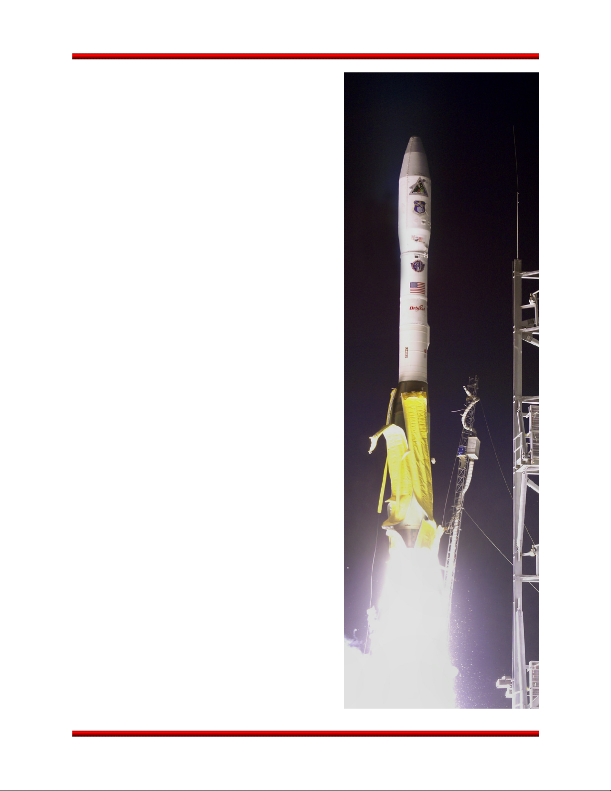
Figure 2.1-1. Minotaur I Launch Vehicle ...................................................................................................... 4
Figure 2.3-1. OSP Minotaur I Launch Vehicle Configuration ....................................................................... 5
Figure 2.3.1-1. Minotaur I LSA Being Lifted out of Transporter Erector ...................................................... 6
Figure 2.3.2-1. Minotaur I Upper Stack Assembly Processing at Orbital’s Vehicle Assembly Building
at VAFB ................................................................................................................................ 6
Figure 2.3.4-1. Minotaur I 50” Fairing and Handling Fixtures ...................................................................... 8
Figure 2.4-1. Minotaur I EGSE Configuration ............................................................................................ 10
Figure 3.1-1. Minotaur I Generic Mission Profile........................................................................................ 11
Figure 3.2-1. Flexible Processing and Portable GSE Allows Operations from Multiple Ranges or
Austere Site Options ............................................................................................................. 12
Figure 3.2-2. Launch Site Inclinations ........................................................................................................ 12
Figure 3.3-1. Minotaur I Performance Curves for VAFB Launches ........................................................... 14
Figure 3.3-2. Minotaur I Performance Curves for KLC Launches .............................................................. 15
Figure 3.3-3. Minotaur I Performance Curves for CCAFS Launches ........................................................ 15
Figure 3.3-4. Minotaur I Performance Curves for WFF Launches ............................................................. 16
Figure 3.3-5. Minotaur I with 61” Fairing Performance Curves for VAFB Launches ................................. 16
Figure 3.3-6. Minotaur I with 61” Fairing Performance Curves for KLC Launches .................................... 17
Figure 3.3-7. Minotaur I with 61” Fairing Performance Curves for CCAFS Launches............................... 17
Figure 3.3-8. Minotaur I with 61” Fairing Performance Curves for WFF Launches ................................... 18
Figure 4.1.1-1. Payload CG Net Transient Lateral Acceleration Envelope ............................................... 21
Figure 4.1.2-1. Minotaur I 3-Sigma Maximum Axial Acceleration as a Function of Payload Mass ........... 22
Release 3.0 March 2014 viii
Page 10

Minotaur I User’s Guide Table of Contents
PAGE
Figure 4.3-1. Payload Acoustic Environment during Liftoff and Flight ....................................................... 23
Figure 4.2-1. Payload Random Vibration Environment during Flight ........................................................ 23
Figure 4.4-1. Maximum Shock Environment – Launch Vehicle to Payload ............................................... 24
Figure 4.4-2. Maximum Shock Environment – Payload to Launch Vehicle ............................................... 24
Figure 4.6.1-1. Minotaur I HVAC System Provides Conditioned Air to the Payload.................................. 25
Figure 4.6.2-1. Typical Minotaur I Fairing Pressure Profile ....................................................................... 26
Figure 5.1.1.1-1. 50” Payload Fairing Dynamic Envelope with 38” (97 cm) Diameter
Payload Interface ............................................................................................................ 29
Figure 5.1.2.1-1. 61” Payload Fairing Dynamic Envelope with 38” (97 cm) Diameter
Payload Interface ............................................................................................................ 30
Figure 5.1.3-1. 50” Payload Fairing Access Door Placement Zone .......................................................... 31
Figure 5.2.1-1. Minotaur Coordinate System ............................................................................................. 33
Figure 5.2.4.1.1-1. COSMIC Spacecraft Configuration Utilized the Orbital MicroStar Bus to
Fly Six SVs ................................................................................................................... 35
Figure 5.2.4.1.1-2. JAWSAT Multiple Payload Adapter Load Bearing Spacecraft .................................... 35
Figure 5.2.4.1.1-3. Five Bay Multiple Payload Adapter Concept ............................................................... 36
Figure 5.2.4.1.2-1. DPAF Configuration ..................................................................................................... 36
Figure 5.2.5.1-1. Orbital 38” Separation System ....................................................................................... 38
Figure 5.2.5.2-1. 38” Planetary Sciences Motorized Lightband ................................................................ 39
Figure 5.2.5.3-1. RUAG 937S 38” Separation System ............................................................................. 39
Figure 5.3-1. Payload Electrical Interface Block Diagram Payload Interface Circuitry .............................. 40
Figure 5.3.1-1. Payload Umbilical 1:1 Pin Outs ......................................................................................... 41
Figure 6.1-1. Mission Integration Team ..................................................................................................... 45
Figure 6.2-1. Typical Minotaur Mission Integration Schedule .................................................................... 47
Figure 6.2-2. Typical Mission Field Integration Schedule .......................................................................... 48
Figure 7-1. Hardware Flow – Factory to Launch Site ................................................................................ 55
Figure 7.1-1. Launch Vehicle Processing Flow.......................................................................................... 56
Figure 7.1.5-1. Minotaur I Processing Is Performed at the MPF at VAFB ................................................. 57
Figure 7.3.4-1. Notional Minotaur Countdown Timeline ........................................................................... 60
Figure 7.3.4-2. Minotaur I Prepared for Launch ......................................................................................... 60
Figure 8.3-1. GN2 Purge Interface To Minotaur Fairing (Flyaway at Liftoff) .............................................. 62
Figure 8.4-1. Multiple Access Doors Were Demonstrated on the Optional Minotaur I Large Fairing ........ 63
Figure 8.6-1. Minotaur Team Has Extensive Experience in a Payload Processing
Clean Room Environment ..................................................................................................... 64
Figure 8.7-1. Orbital’s Secure FTS System Block Diagram ....................................................................... 65
Figure 8.8-1. TDRSS 20W LCT2 Transmitter and Cavity Backed S-band Antenna .................................. 66
Figure 8.8-2. TDRSS Notional Telemetry Flow.......................................................................................... 66
Release 3.0 March 2014 ix
Page 11

Minotaur I User’s Guide Table of Contents
PAGE
Figure 8.10-1. Minotaur I SRSS Significantly Attenuates Peak LV Dynamic Environments ..................... 67
Figure 8.11-1. Operational and Disposal LEOs ......................................................................................... 67
Figure 8.13.1-1. Minotaur I Commercial Offers Exceptional Performance with Proven Reliability ............ 68
Figure 8.15-1. Typical Propellant Loading Schematic ............................................................................... 69
Figure 8.15-2. UPC Provides Reliable and Demonstrated Hydrazine Servicing for Minotaur ................... 70
Figure 8.18-1. Minotaur I Lite Ballistic Performance .................................................................................. 71
Figure 8.17-1. P-PODs Have Successfully Flown On Multiple Minotaur Missions .................................... 71
Figure 8.18-2. Minotaur I-Lite Replaces the Orion 38 with a Low Cost and Risk Simple
Aluminum Cylinder .............................................................................................................. 72
Figure 8.19-1. Minotaur IV Vehicles Have Successfully Launched From KLC .......................................... 73
Figure 8.19-3. Minotaur I Vehicles Have Successfully Launched Multiple Times From Wallops .............. 73
Figure 8.19-2. Launch Complex 46 at CCAFS Supports All Minotaur Configurations .............................. 73
LIST OF TABLES
Table 3.3-1. Common Mission Options and Associated Masses (These Masses Must Be Subtracted
from the LV Performance) ..................................................................................................... 14
Table 3.4-1. Minotaur I Injection Accuracy ................................................................................................. 18
Table 3.5-1. Typical Pre-Separation Payload Pointing and Spin Rate Accuracies ................................... 19
Table 4.8-1. Minotaur I Launch Vehicle RF Emitters and Receivers ......................................................... 27
Table 5.2.5-1. Minotaur I Separation System Options ............................................................................... 37
Table 5.4.2-1. Payload Mass Properties Measurement Tolerance ........................................................... 43
Table 8.9-1. Enhanced Insertion Accuracies ............................................................................................. 66
LIST OF APPENDICES
A. PAYLOAD QUESTIONNAIRE ..............................................................................................................A-1
Release 3.0 March 2014 x
Page 12

Minotaur I User’s Guide Glossary
6DOF
Six Degrees of Freedom
A/D
Arm/Disarm
AADC
Alaska Aerospace Development
ACAT-1
Acquisition Category 1
ACS
Attitude Control System
AFRL
Air Force Research Laboratory
ait
Atmospheric Interceptor
AIT
Assembly Integration Trailer
AODS
All-Ordnance Destruct System
BCM
Booster Control Module
BER
Bit Error Rate
C/CAM
Collision/ Contamination
C/D
Command/Destruct
CBOD
Clamp Band Opening Device
CCAFS
Cape Canaveral Air Force Station
CDR
Critical Design Review
CG
Center of Gravity
CLA
Coupled Loads Analysis
CLF
Commercial Launch Facility
CVCM
Collected Volatile Condensable
DIACAP
DoD Information Assurance
DoD
Department of Defense
DPAF
Dual Payload Adapter Fitting
ECU
Electronic Control Unit
EGSE
Electrical Ground Support
EMC
Electromagnetic Compatibility
EME
Electromagnetic Environment
EMI
Electromagnetic Interference
ER
Eastern Range
FAA
Federal Aviation Administration
FRR
Flight Readiness Review
FTLU
Flight Termination Logic Unit
FTS
Flight Termination System
GFE
Government Furnished Equipment
GFP
Government Furnished Property
GN2
gaseous nitrogen
GPB
GPS Positioning Beacon
GPS
Global Positioning System
GTO
Geosynchronous Transfer Orbit
HAPS
Hydrazine Auxiliary Propulsion
HVAC
Heating, Ventilation, and Air
I&T
Integration and Test
I/O
Input/Output
ICD
Interface Control Document
INS
Inertial Navigation System
IRRT
Independent Readiness Review
IV&V
Independent Verification and
IVT
Interface Verification Test
KLC
Kodiak Launch Complex
KSC
Kennedy Space Center
LCR
Launch Control Room
LEO
Low Earth Orbit
LEV
Launch Equipment Vault
LITVC
Liquid Injection Thrust Vector
LOCC
Launch Operations Control Center
LRR
Launch Readiness Review
LSA
Lower Stack Assembly
LSA
Launch Stool Assembly
LSE
Launch Support Equipment
LV
Launch Vehicle
MA
Mission Assurance
MACH
Modular Avionics Control
MARS
Mid-Atlantic Regional Spaceport
MDR
Mission Design Review
MDR
Mission Dress Rehearsal
MGSE
Mechanical Ground Support
MICD
Mechanical Interface Control
MLB
Motorized Lightband
MM
Minuteman
MODS
Mechanical Ordnance Destruct
MPA
Multiple Payload Adaptor
MPE
Maximum Predicted Environment
MPF
Minotaur Processing Facility
MRD
Mission Requirements Document
MRR
Mission Readiness Review
MST
Mission Simulation Test
System
Corporation
Technology
Avoidance Maneuver
Mass
Conditioning
Team
Validation
Control
Certification and Accreditation
Process
Equipment
Hardware
Equipment
Drawing
System
Release 3.0 March 2014 xi
Page 13

Minotaur I User’s Guide Glossary
MTO
Medium Transfer Orbit
NASA
National Aeronautics and Space
NCU
Nozzle Control Unit
NRE
Non-Recurring Engineering
NTO
Nitrogen Tetroxide
ODM
Ordnance Driver Module
OR
Operations Requirements
OSP-3
Orbital Suborbital Program 3
PAF
Payload Attach Fitting
PCM
Pulse Code Modulation
PDR
Preliminary Design Review
PEM
Program Engineering Manager
PPF
Payload Processing Facility
P-POD
Poly-Pico Orbital Deployer
PRD
Program Requirements Document
RAAN
Right Ascension of Ascending
RCS
Roll Control System
RF
Radio Frequency
RWG
Range Working Group
S/A
Safe and Arm
SCAPE
Self-Contained Atmospheric
SD
Space Development and Test
SDL
SD Launch Systems Division
SEB
Support Equipment Building
SLC-8
Space Launch Complex 8
SLV
Space Launch Vehicle
SMC
Space and Missile Systems Center
SRSS
Softride for Small Satellites
SSI
Spaceport Systems International
START
Strategic Arms Reduction Treaty
SV
Space Vehicle
TDRSS
Telemetry Data Relay Satellite
TLI
Trans-Lunar Injection
TML
Total Mass Loss
TVC
Thrust Vector Control
UPC
United Paradyne Corporation
USA
Upper Stack Assembly
USAF
United States Air Force
VAFB
Vandenberg Air Force Base
WFF
Wallops Flight Facility
WP
Work Package
Administration
Node
Protective Ensemble
Directorate
System
Release 3.0 March 2014 xii
Page 14
Minotaur I User’s Guide Section 1.0 – Introduction
1. INTRODUCTION
This User’s Guide is intended to familiarize payload
mission planners with the capabilities of the Orbital
Suborbital Program 3 (OSP-3) Minotaur I Space Launch
Vehicle (SLV) launch service. This document provides an
overview of the Minotaur I system design and a
description of the services provided to our customers.
Minotaur I offers a variety of enhanced options to allow for
maximum flexibility in satisfying the objectives of single or
multiple payloads.
The user’s handbook is not intended as a design
document but rather it is to be used to select a launch
vehicle that meets the requirements of the payload. This
document describes typical environments seen on
previous missions. Each spacecraft is unique and will
require detailed analysis early in the program.
The primary mission of Minotaur I is to provide low cost,
high reliability launch services to government-sponsored
payloads. Minotaur I accomplishes this by using flight
proven components with significant flight heritage. The
philosophy of placing mission success as the highest
priority is reflected in the success and accuracy of all
Minotaur missions to date.
The Minotaur I launch vehicle system is composed of a
flight vehicle and ground support equipment. Each
element of the Minotaur I system has been developed to
simplify the mission design and payload integration
process and to provide safe, reliable space launch
services. This User’s Guide describes the basic elements
of the Minotaur I system as well as optional services that
are available. In addition, this document provides general
vehicle performance, defines payload accommodations
and environments, and outlines the Minotaur I mission
integration process.
The Minotaur I system can operate from a wide range of
launch facilities and geographic locations. The system is
compatible with, and will typically operate from,
commercial spaceport facilities and existing U.S.
Government ranges at Vandenberg Air Force Base
(VAFB), Cape Canaveral Air Force Station (CCAFS),
Wallops Flight Facility (WFF), and Kodiak Launch
Complex (KLC). This User’s Guide describes Minotaur Iunique integration and test approaches (including the
typical operational timeline for payload integration with the
Release 3.0 March 2014 1
Page 15
Minotaur I User’s Guide Section 1.0 – Introduction
Minotaur I vehicle) and the existing ground support equipment that is used to conduct Minotaur I
operations.
1.1. Minotaur Family Performance and Capability
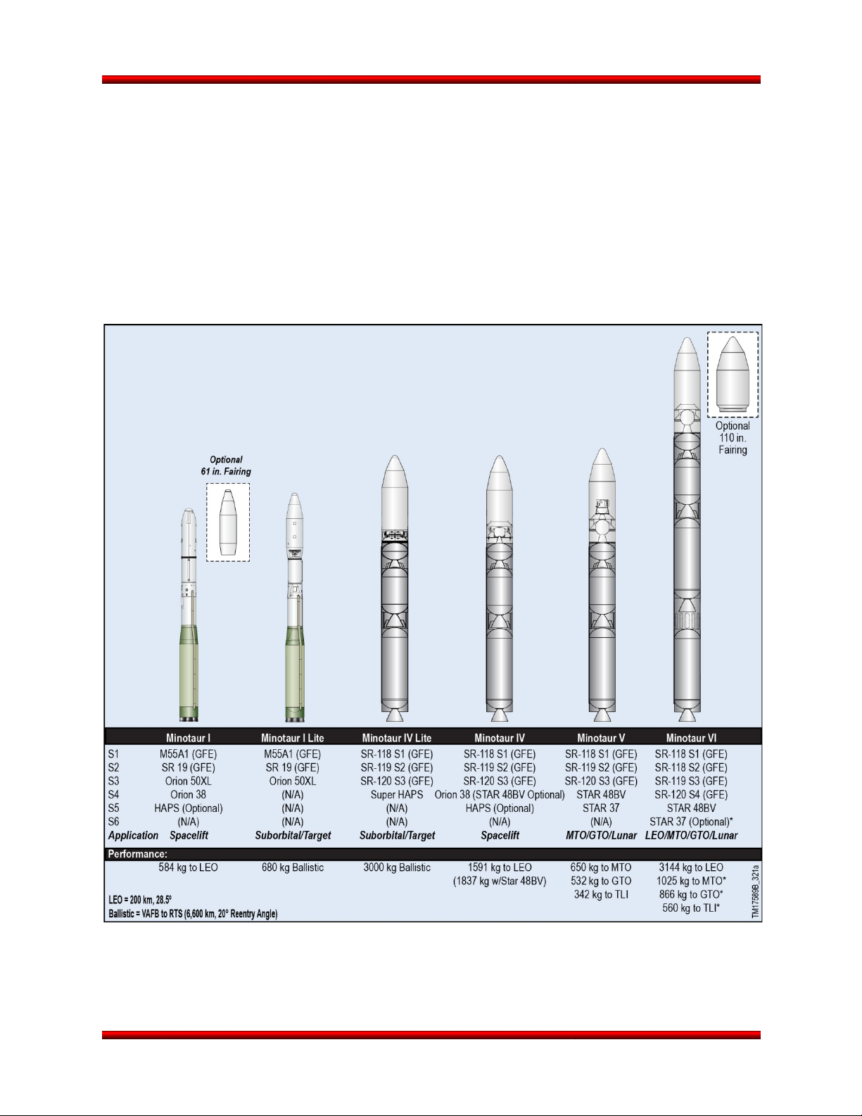
Figure 1.1-1 shows the Minotaur family of launch vehicles, which is capable of launching a wide range of
payload sizes and missions. Representative space launch performance across the Minotaur fleet is
shown in Figure 1.1-2 to illustrate the relative capability of each configuration. In addition to space launch
capabilities, the Minotaur I Lite and Minotaur IV Lite configurations are available to meet suborbital
payload needs for payloads weighing up to 3000 kg. This User’s Guide covers the Minuteman-based
Minotaur I. Please refer to the Minotaur IV – V – VI User’s Guide for information on the Peacekeeperbased Minotaur vehicles.
Figure 1.1-1. The Minotaur Family of Launch Vehicles
Release 3.0 March 2014 2
Page 16
Minotaur I User’s Guide Section 1.0 – Introduction
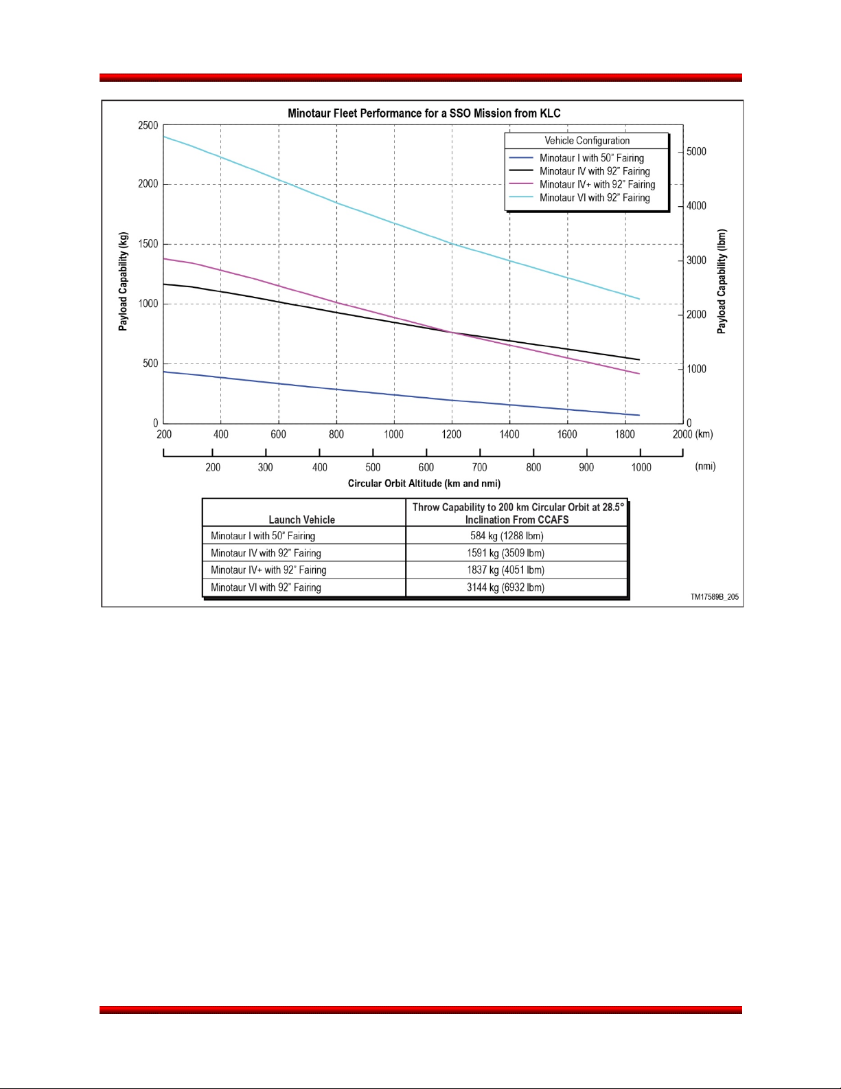
Figure 1.1-2. Space Launch Performance for the Minotaur Family Demonstrates a Wide Range of
Payload Lift Capability
Release 3.0 March 2014 3
Page 17
Minotaur I User’s Guide Section 2.0 – Minotaur I Configurations
2. MINOTAUR I CONFIGURATIONS
2.1. Minotaur I Launch System Overview
The Minotaur I launch vehicle, shown in
Figure 2.1-1, was developed by Orbital for the
United States Air Force (USAF) to provide a cost
effective, reliable and flexible means of placing
small satellites into orbit. Orbital is the launch
vehicle developer and manufacturer under the
Orbital Suborbital Program 3 (OSP-3) contract for
the U.S. Air Force. An overview of the system and
available launch services is provided within this
section, with specific elements covered in greater
detail in the subsequent sections of this User’s
Guide.
Minotaur I has been designed to meet the needs
of United States Government-sponsored
customers at a lower cost than commercially
available alternatives through the use of surplus
Minuteman boosters. OSP-3 requirements
emphasize system reliability, transportability, and
operation from multiple launch sites. Minotaur I
draws on the successful heritage of Orbital’s
space launch vehicles and the Minuteman II system of the USAF to meet these requirements. Orbital has
built upon these legacy systems with enhanced avionics components and advanced composite structures
to meet the payload-support requirements of the OSP-3 program. Combining these improved subsystems
with the long and successful history of the Minuteman II boosters has resulted in a simple, robust, selfcontained launch system with a proven success record that is fully operational to support governmentsponsored small satellite launches.
The Minotaur I system also includes a complete set of transportable Launch Support Equipment (LSE)
designed to allow Minotaur I to be operated as a self-contained satellite delivery system. The Electrical
Ground Support Equipment (EGSE) has been developed to be portable and adaptable to varying levels of
infrastructure. While the Minotaur I system is capable of self-contained operation at austere launch sites
using portable vans, typical operations occur from permanent facilities on established ranges.
The Minotaur I system is designed to be capable of launch from four commercial Spaceports (Alaska,
California, Florida, and Mid-Atlantic), as well as from existing U.S. Government facilities at VAFB and
CCAFS. A Launch Control Room (LCR) serves as the control center for conducting a Minotaur I launch
and includes consoles for Orbital, range safety, and limited customer personnel. Further description of the
Launch Support Equipment is provided in Section 2.4.
2.2. Minotaur I Launch Service
The Minotaur I Launch Service is provided through the combined efforts of the USAF and Orbital, along
with associate contractors and Commercial Spaceports. The primary customer interface will be with the
USAF Space and Missile Systems Center, Space Development and Test Directorate, Launch Systems
Figure 2.1-1. Minotaur I Launch Vehicle
Release 3.0 March 2014 4
Page 18
Minotaur I User’s Guide Section 2.0 – Minotaur I Configurations
Division (SDL). Orbital is the launch vehicle
provider. This integrated team will be referred to
collectively as “OSP” throughout the User’s Guide.
Where necessary, interfaces that are associated
with a particular member of the team will be
referred to directly (i.e., Orbital or SDL).
OSP provides all of the necessary hardware,
software and services to integrate, test and launch
a payload into its prescribed orbit. In addition,
OSP will complete all the required agreements,
licenses and documentation to successfully
conduct Minotaur I operations. The Minotaur I
mission integration process completely identifies,
documents, and verifies all spacecraft and
mission requirements.
2.3. Minotaur I Launch Vehicle
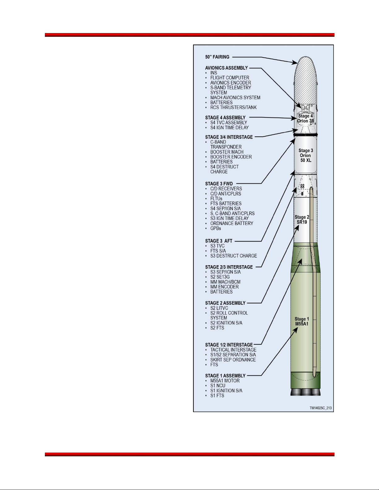
The Minotaur I vehicle, shown in expanded view
in Figure 2.3-1, is a four stage, inertially guided,
all solid propellant ground launched vehicle.
Conservative design margins, state-of-the-art
structural systems, a modular avionics
architecture, and simplified integration and test
capability, yield a robust, highly reliable launch
vehicle design. In addition, Minotaur I payload
accommodations and interfaces have been
designed to satisfy a wide range of potential
payload requirements.
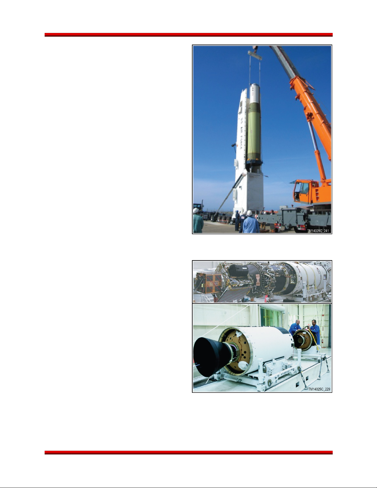
2.3.1. Lower Stack Assembly
The Lower Stack Assembly (LSA), shown in
Figure 2.3.1-1, consists of the refurbished
Government Furnished Equipment (GFE)
Minuteman Stages 1 and 2. Only minor
modifications are made to the boosters, including
harness interface changes and conversion from
All-Ordnance Destruct System (AODS) to Modular
Mechanical Ordnance Destruct System (MMODS)
Flight Termination System (FTS).
The first stage consists of the Minuteman II
M55A1 solid propellant motor, Nozzle Control
Units (NCU), Stage 1 Ignition Safe/Arm, S1/S2
Interstage and Stage 1 MMODS FTS. Four
gimbaled nozzles provide three axis control during
first stage burn. The second stage consists of a refurbished Minuteman II SR19 motor, Liquid Injection
Figure 2.3-1. OSP Minotaur I Launch Vehicle
Configuration
Release 3.0 March 2014 5
Page 19
Minotaur I User’s Guide Section 2.0 – Minotaur I Configurations
Processing Facility at VAFB
Thrust Vector Control (LITVC) subsystem, S2
ignition safe/arm device, a Roll Control System
(RCS), and the Stage 2 MMODS FTS
components. Attitude control during second stage
burn is provided by the operational LITVC and hot
gas roll control.
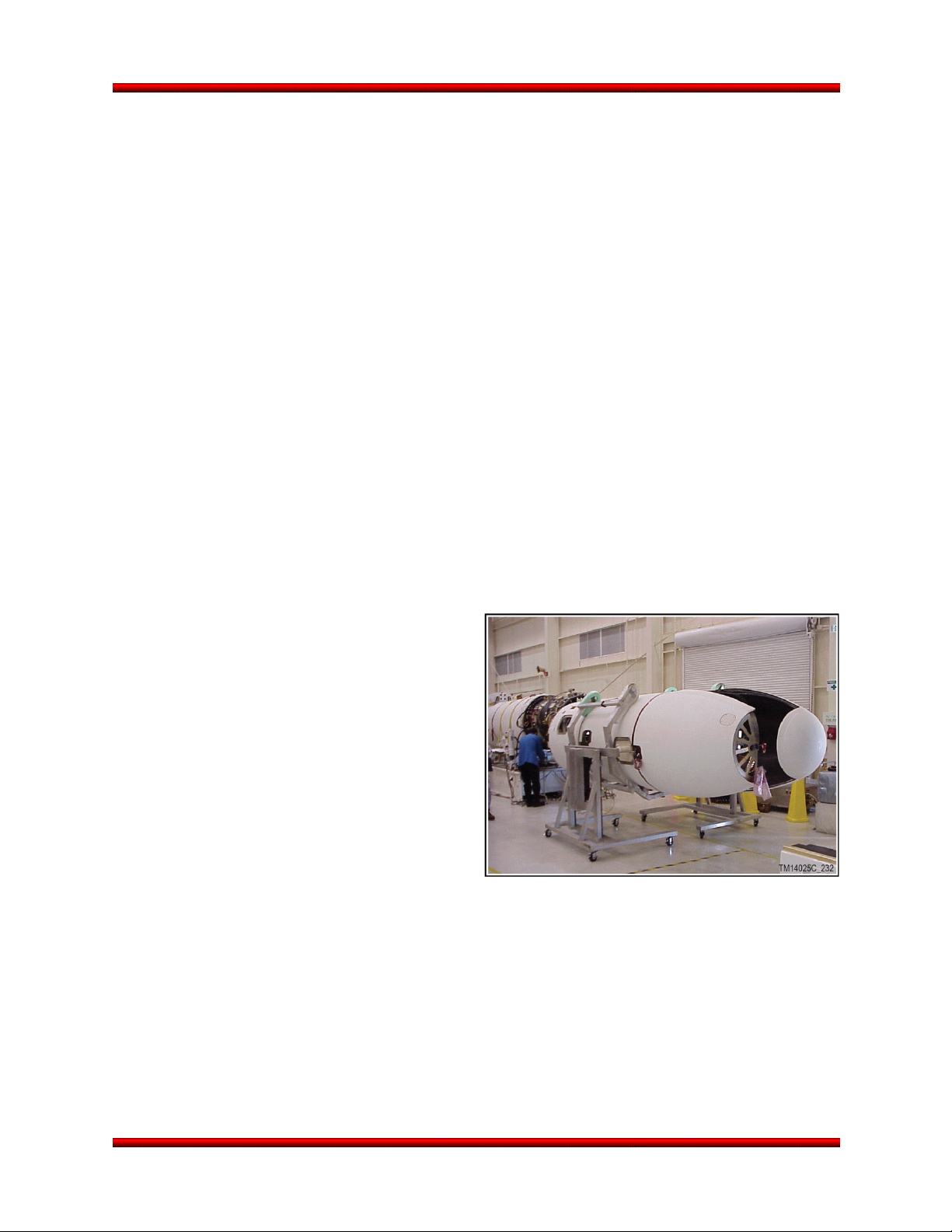
2.3.2. Upper Stack Assembly
The Minotaur I Upper Stack is composed of the
Stage 3 and 4 motors, their associated
interstages, the avionics assembly, and,
ultimately, the payload and payload fairing. The
Stage 3 and 4 motors are the Orion 50 XL and
Orion 38, respectively. These motors were
originally developed for Orbital’s Pegasus
program and are used in a similar manner on the
ground-launched Minotaur I vehicle. Common
design features, materials and production
techniques are applied to both motors to
maximize reliability and production efficiency. The
motors are fully flight qualified based on their
heritage, conservative design, ground static fires
and over 60 launches. Processing of the
Minotaur I Upper Stack is conducted at the
Minotaur Processing Facility (MPF), as shown in
Figure 2.3.2-1.
2.3.2.1. Avionics
The Minotaur I avionics system has heritage and
commonality across the Minotaur fleet. The flight
computer is a 32-bit multiprocessor architecture. It
provides communication with vehicle subsystems,
the LSE, and if required, the payload via standard
RS-422 serial links and discrete I/O. The avionics
system design incorporates Orbital’s innovative,
flight proven Modular Avionics Control Hardware
(MACH). The MACH consists of standardized,
function-specific modules that are combined in
stacks of up to 10 modules to meet mission
requirements. The functional modules from which
the MACH stacks are created include power
transfer, ordnance initiation, booster interface,
communication, and telemetry processing. These
modules provide an array of functional capability
and flexibility.
Figure 2.3.1-1. Minotaur I LSA Being Lifted out
of Transporter Erector
Figure 2.3.2-1. Minotaur I Upper Stack
Assembly Processing at Orbital’s Minotaur
Release 3.0 March 2014 6
Page 20

Minotaur I User’s Guide Section 2.0 – Minotaur I Configurations
2.3.2.2. Attitude Control Systems
The Minotaur I Control System provides three-axis attitude control throughout boosted flight and coast
phases. Stages 1 and 2 utilize the Minuteman Thrust Vector Control (TVC) systems. The Stage 1 TVC is
a four-nozzle hydraulic system, while the Stage 2 system combines liquid injection for pitch and yaw
control with hot gas roll control. Stages 3 and 4 utilize the same TVC systems as Minotaur IV. They
combine single-nozzle electromechanical TVC for pitch and yaw control with a three-axis cold-gas
Attitude Control System (ACS) resident in the avionics section providing roll control.
Attitude control is achieved using a three-axis autopilot. Stages 1 and 2 fly a pre-programmed attitude
profile based on trajectory design and optimization. Stage 3 uses a set of pre-programmed orbital
parameters to place the vehicle on a trajectory toward the intended insertion apse. The extended coast
between Stages 3 and 4 is used to orient the vehicle to the appropriate attitude for Stage 4 ignition based
upon a set of pre-programmed orbital parameters and the measured performance of the first three
stages. Stage 4 utilizes energy management to place the vehicle into the proper orbit. After the final boost
phase, the three-axis cold-gas attitude control system is used to orient the vehicle for spacecraft
separation, contamination and collision avoidance and downrange downlink maneuvers. The autopilot
design is a modular object oriented software design, so additional payload requirements such as rate
control or celestial pointing can be accommodated with minimal additional development.
2.3.2.3. Telemetry Subsystem
The Minotaur I telemetry subsystem provides real-time health and status data of the vehicle avionics
system, as well as key information regarding the position, performance and environment of the Minotaur I
vehicle. This data is used by both Orbital and the range safety personnel to evaluate system
performance. The Minotaur I baseline telemetry subsystem provides a number of dedicated payload
discrete (bi-level) and analog telemetry monitors through dedicated channels in the launch vehicle
encoder. The baseline telemetry system has a 1.5 Mbps data rate for both payload and Minotaur launch
vehicle telemetry. To allow for flexibility in supporting evolving mission requirements, the output data rate
can be selected over a wide range from 2.5 kbps to 10 Mbps (contingent on link margin and Bit Error
Rate (BER) requirements). The telemetry subsystem nominally utilizes Pulse Code Modulation (PCM)
with a RNRZ-L format. Other types of data formats, including NRZ-L, S, M, and Bi-phase may be
implemented if required to accommodate launch range limitations. Furthermore, the launch vehicle
telemetry system has the capability to take payload telemetry as an input, randomize if required, and
downlink that dedicated payload link from launch through separation. That capability is available as a
non-standard option.
The Enhanced Telemetry option as described in the Enhancements section 8.5 augments the existing
baseline telemetry system by providing a dedicated telemetry link with a baseline data rate of 2 Mbps.
This Enhanced Telemetry link is used to provide further insight into the mission environment due to
additional payload, LV, or experiment data acquisition requirements. Supplementary instrumentation or
signals such as strain gauges, temperature sensors, accelerometers, analog, or digital data can be
configured to meet payload mission-specific requirements.
An Over the Horizon Telemetry option can also be added to provide real-time telemetry coverage during
ground-based telemetry receiving site blackout periods. The Telemetry Data Relay Satellite System
(TDRSS) is used for this capability, and has been successfully demonstrated on past Minotaur missions.
Close to the time when telemetry coverage is lost by ground based telemetry receiving sites, the LV
switches telemetry output to the TDRSS antenna and points the antenna towards the designated satellite.
Release 3.0 March 2014 7
Page 21
Minotaur I User’s Guide Section 2.0 – Minotaur I Configurations
The TDRSS then relays the telemetry to the ground where it is routed to the Launch Control Room for
real-time telemetry updates. Reference Enhancements Section 8.8 for further details on this Over the
Horizon Telemetry option.
Minotaur telemetry is subject to the provisions of the Strategic Arms Reduction Treaty (START). START
treaty provisions require that certain Minotaur I telemetry be unencrypted and provided to the START
treaty office for dissemination to the signatories of the treaty.
2.3.3. Payload Interface
Minotaur provides for a standard non-separating payload interface, with the option of adding an Orbitalprovided payload separation system. Orbital will provide all flight hardware and integration services
necessary to attach non-separating and separating payloads to the Minotaur launch vehicle. Additional
mechanical interface diameters and separation system configurations can readily be provided as an
enhanced option as described in Section 5.0. Further detail on payload electrical, mechanical and launch
support equipment interfaces are detailed in Section 5.0.
Because of its design flexibility, Minotaur can accommodate and has flown missions with multiple
spacecraft. This capability, described in more detail in Section 5.0 of this User’s Guide, permits two or
more smaller payloads to share the cost of a Minotaur I launch, resulting in a lower launch cost for each
as compared to other launch options. Furthermore, Orbital can accommodate small payloads when there
is excess payload and/or mass capability.
2.3.4. Payload Fairing
The baseline Minotaur I 50” fairing, shown in
Figure 2.3.4-1, is identical to the Pegasus fairing
design and has been successfully deployed in
over 40 Pegasus and Minotaur I missions. Due to
differences in vehicle loads and environments, the
Minotaur I implementation allows for a larger
payload envelope than Pegasus. The Minotaur I
payload fairing consists of two composite shell
halves, a nose cap integral to one shell half, and a
separation system. Each shell half is composed of
a cylinder and ogive sections.
Options for payload access doors and enhanced
cleanliness are available. A larger 61” diameter
fairing is also available. Further details on both
fairings are included in Section 5.1.
Figure 2.3.4-1. Minotaur I 50” Fairing and
Handling Fixtures
Release 3.0 March 2014 8
Page 22

Minotaur I User’s Guide Section 2.0 – Minotaur I Configurations
2.4. Launch Support Equipment
The Minotaur I LSE is designed to be readily adaptable to varying launch site configurations with minimal
unique infrastructure required. The EGSE consists of readily transportable consoles that can be housed
in various facility configurations depending on the launch site infrastructure. The EGSE is composed of
three primary functional elements: Launch Control, Vehicle Interface, and Telemetry Data Reduction. The
Launch Control and Telemetry Data Reduction consoles are located in the Launch Control Room (LCR),
or mobile launch equipment van depending on available launch site accommodations. The Vehicle
Interface consoles are located at the launch pad in a permanent structure, typically called a Launch
Equipment Vault (LEV). Fiber optic connections from the Launch Control to the Vehicle Interface consoles
are used for efficient, high bandwidth communications, eliminating the need for copper wire between
locations. The Vehicle Interface consoles provide the junction from fiber optic cables to the cables that
directly interface with the vehicle. Figure 2.4-1 depicts the functional block diagram of the LSE. All
Minotaur EGSE is compliant with the Department of Defense Instruction 8510.01, DoD Information
Assurance Certification and Accreditation Process (DIACAP). Some launch sites have a separate
Support Equipment Building (SEB) that can accommodate additional payload equipment.
The LCR serves as the control center during the launch countdown. The number of personnel that can be
accommodated is dependent on the launch site facilities. At a minimum, the LCR will accommodate
Orbital personnel controlling the vehicle, two Range Safety representatives (ground and flight safety), and
the Air Force Mission Manager. Mission-unique, customer-supplied payload consoles and equipment can
be supported in the LCR and payload equipment at the launch pad can be supported in the LEV or SEB,
if available, within the constraints of the launch site facilities. Interface to the payload through the
Minotaur I payload umbilicals provides the capability for direct monitoring of payload functions. Payload
personnel accommodations will be handled on a mission-specific basis.
All of the Mechanical Ground Support Equipment (MGSE) used to support the Minotaur integration, test
and launch is currently in use and launch demonstrated. MGSE fully supports all Minotaur configurations
and are routinely static load tested to safety factors in compliance with Orbital internal and Range
requirements.
Release 3.0 March 2014 9
Page 23
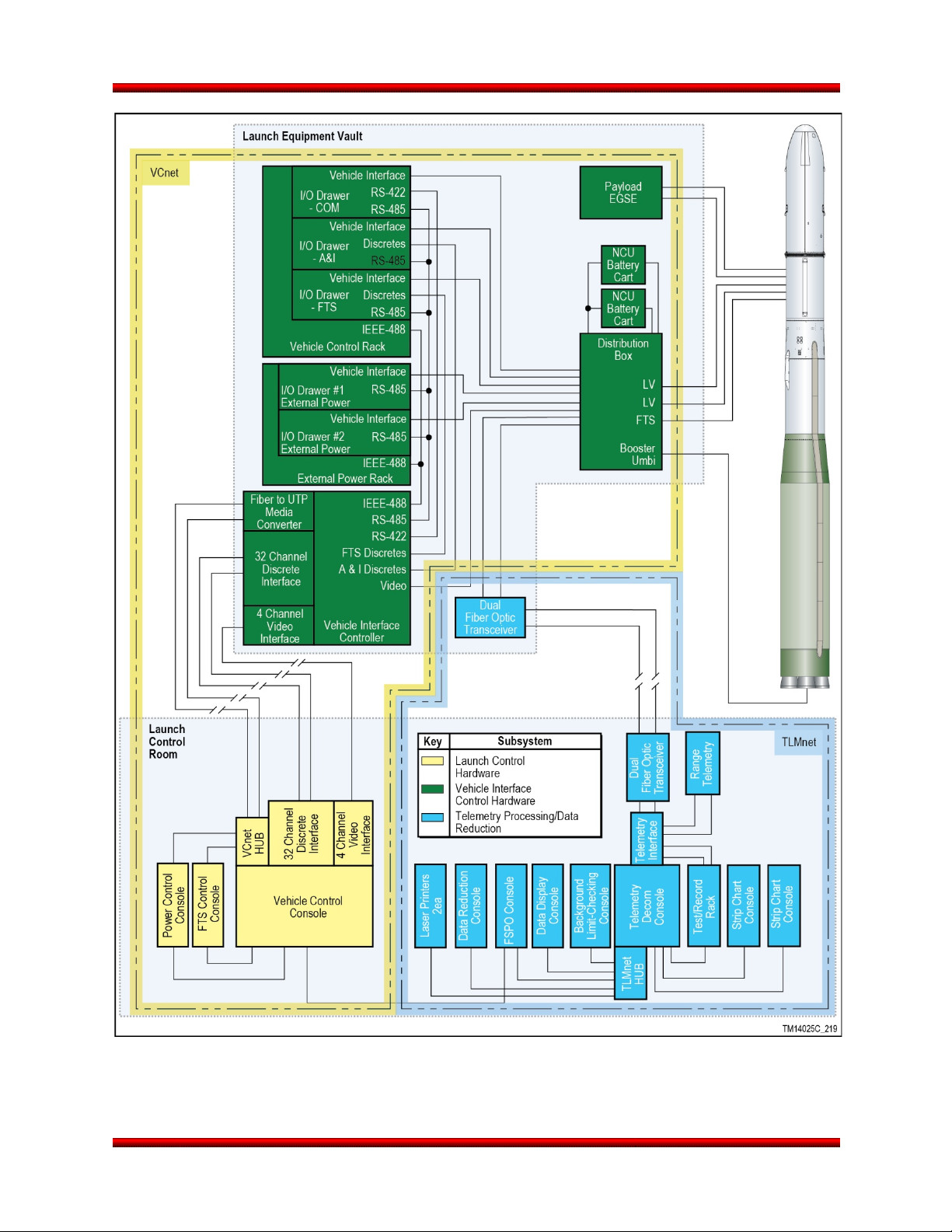
Minotaur I User’s Guide Section 2.0 – Minotaur I Configurations
Figure 2.4-1. Minotaur I EGSE Configuration
Release 3.0 March 2014 10
Page 24
Minotaur I User’s Guide Section 3.0 – General Performance
3. GENERAL PERFORMANCE
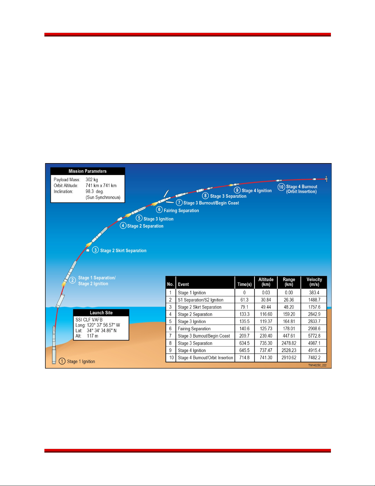
3.1. Mission Profiles
Minotaur I can attain a range of posigrade and retrograde inclinations through the choice of launch sites
made available by the readily adaptable nature of the Minotaur I launch system. A generic mission profile
to a sun-synchronous orbit is shown in Figure 3.1-1. All performance parameters presented within this
User’s Guide are typical for most expected payloads. However, performance may vary depending on
unique payload or mission characteristics. Specific requirements for a particular mission must be
coordinated with OSP. Once a mission is formally initiated, the requirements will be documented in the
Mission Requirements Document (MRD). The MRD is the requirement kick off document that initiates the
contractual agreement and flows the payload requirements to Orbital. The MRD establishes the data
required to begin formal trajectory analysis as well as Coupled Loads Analyses (CLAs). Further detail will
be captured in the Payload-to-Launch Vehicle Interface Control Document (ICD).
Figure 3.1-1. Minotaur I Generic Mission Profile
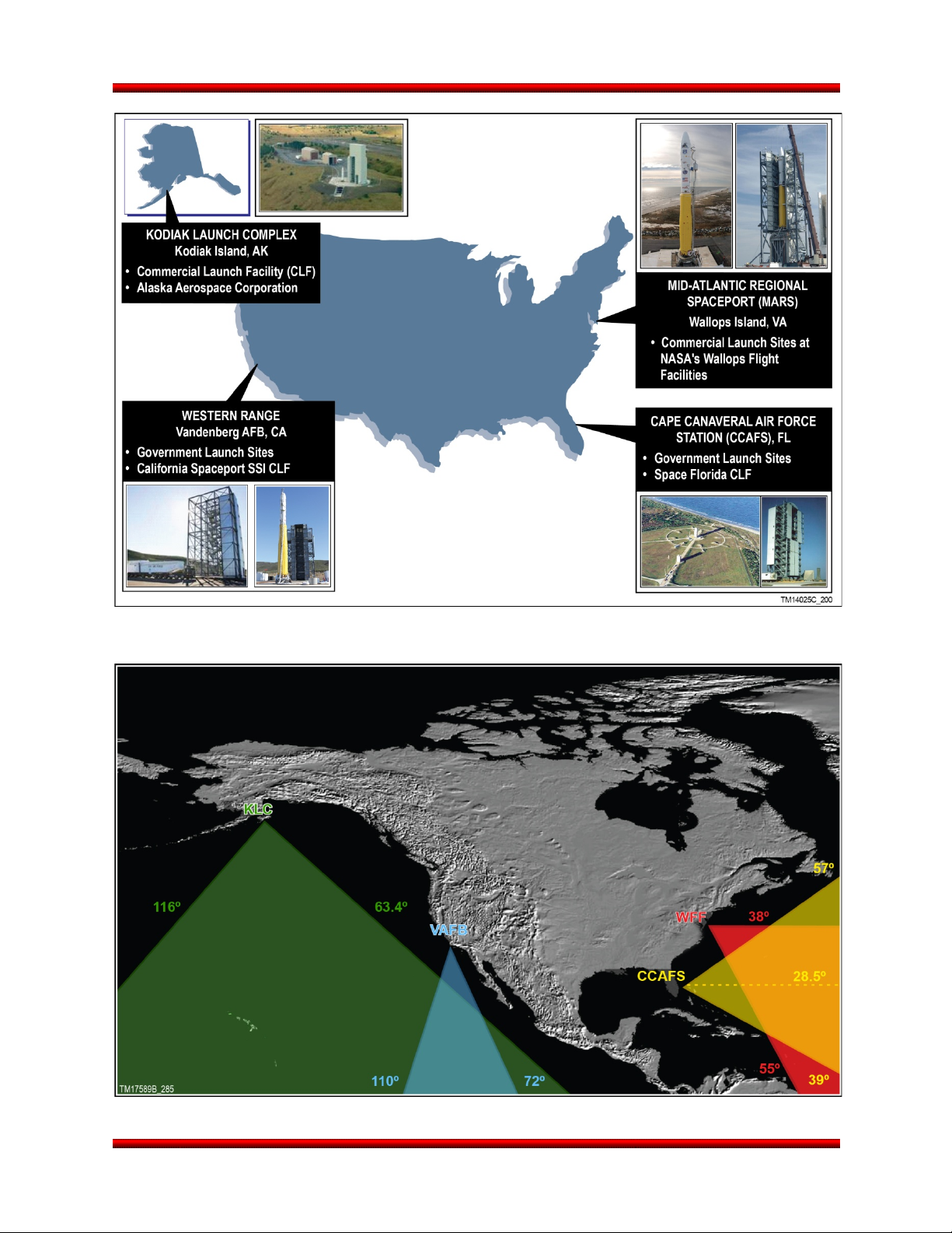
3.2. Launch Sites
Depending on the specific mission, Minotaur I can operate from East and West Coast launch sites as
illustrated in Figure 3.2-1. The corresponding range inclination capabilities are shown in Figure 3.2-2.
Specific performance parameters are presented in Section 3.3. The baseline launch site for Minotaur I is
VAFB.
Release 3.0 March 2014 11
Page 25
Minotaur I User’s Guide Section 3.0 – General Performance
Figure 3.2-1. Flexible Processing and Portable GSE Allows Operations from Multiple Ranges or
Austere Site Options
Figure 3.2-2. Launch Site Inclinations
Release 3.0 March 2014 12
Page 26

Minotaur I User’s Guide Section 3.0 – General Performance
3.2.1. Western Launch Sites
For missions requiring high inclination orbits (greater than 60°), launches can be conducted from facilities
at VAFB or Kodiak Island, AK, as shown in Figure 3.2-2. Inclinations below 72° from VAFB are possible,
but require an out-of-plane dogleg, thereby reducing payload capability. Minotaur I is nominally launched
from the California Spaceport facility, Space Launch Complex 8 (SLC-8) operated by Spaceport Systems
International (SSI), on South VAFB. The launch facility at Kodiak Island, operated by the Alaska
Aerospace Development Corporation (AADC) has been used for both orbital and suborbital launches,
including past launches of Minotaur IV.
3.2.2. Eastern Launch Sites
For easterly launch azimuths to achieve orbital inclinations between 28.5° and 55°, launches can be
conducted from facilities at Cape Canaveral Air Force Station, FL (CCAFS) or Wallops Island, VA (WFF).
Launches from Florida will nominally use the Space Florida launch facilities at LC-46 on CCAFS. Typical
inclinations are from 28.5° to 50°; however, higher inclination trajectories may be accommodated by using
northerly ascent trajectories. These would need to consider the potential of European overflight and
require range safety assessment. The Mid-Atlantic Regional Spaceport (MARS) facilities at the WFF may
be used for inclinations from 37.8° to 55°. Some inclinations and/or altitudes may have reduced
performance due to range safety considerations and will need to be evaluated on a case-by-case
mission-specific basis.
3.2.3. Alternate Launch Sites
Other launch facilities can be readily used given the flexibility designed into the Minotaur I vehicle, ground
support equipment, and the various interfaces. Orbital has experience launching vehicles from a variety of
sites around the world. To meet the requirements of performing mission operations from alternative,
austere launch sites, Orbital can provide self contained, transportable shelters for launch operations as
an unpriced option. The mobile equivalent of the LCR is the Launch Support Van (LSV), and the mobile
LEV is the Launch Equipment Van.
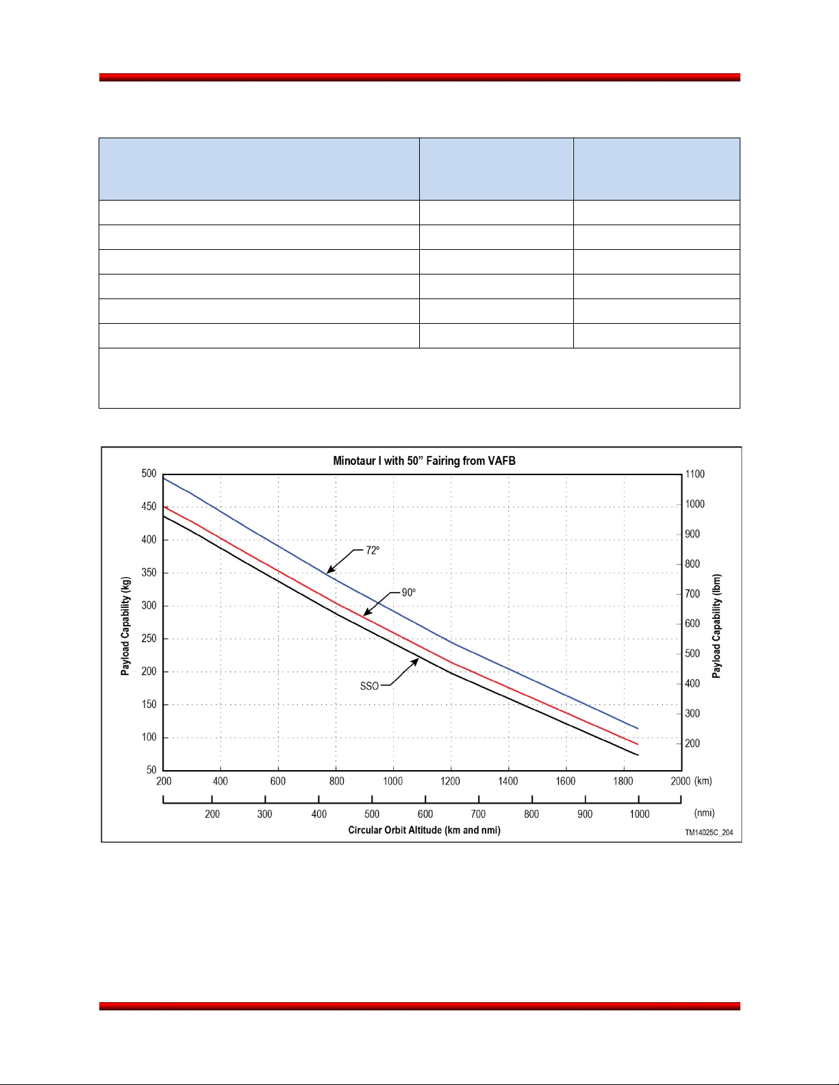
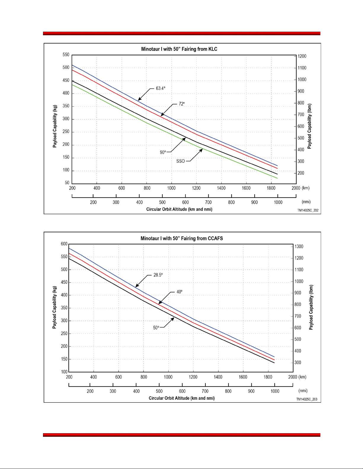
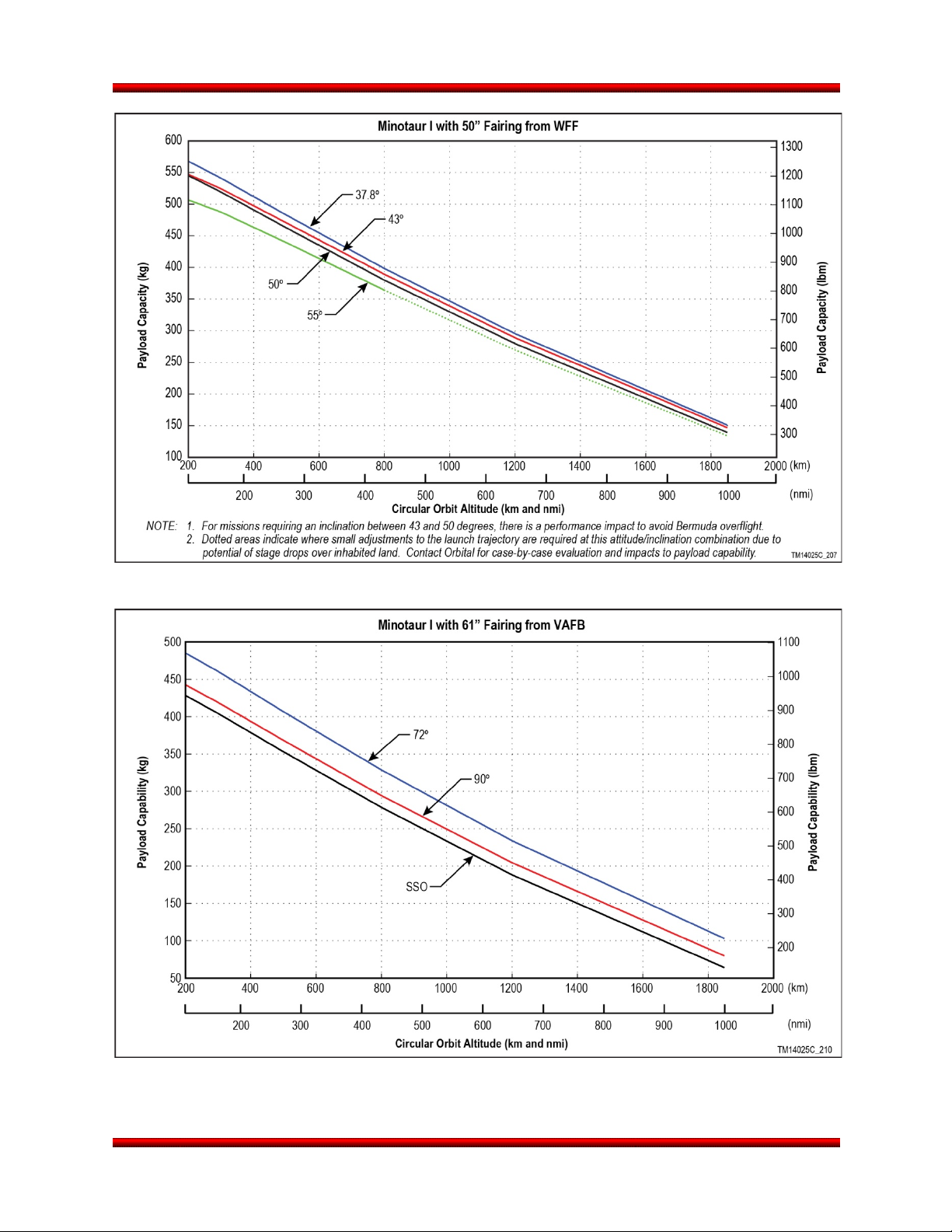
3.3. Performance Capability
Minotaur I performance curves for circular orbits of various altitudes and inclinations are detailed in Figure
3.3-1 through Figure 3.3-8 for launches from all four Spaceports in metric and English units. These
performance curves provide the total mass above the standard, non-separating interface. The mass of
the separation system and any Payload Attach Fitting (PAF) that is attached to the 38.81” interface, is to
be accounted for in the payload mass allocation. Table 3.3-1 shows a number of common options and the
mass associated with each.
Release 3.0 March 2014 13
Page 27
Minotaur I User’s Guide Section 3.0 – General Performance
Table 3.3-1. Common Mission Options and Associated Masses
(These Masses Must Be Subtracted from the LV Performance)
Option
Total Mass (kg)
(These Masses Must Be
Subtracted from the LV
Performance)
Portion of Total Mass
That Remains with SV
Post Separation (kg)
Enhanced Telemetry 9.85 0
TDRSS 8.54 0
38” Orbital Separation System1 12.24 4.0
38” RUAG Low Shock Separation System (937S)1 19.89 6.16
38” Lightband1 8.85 2.52
38” Softride and Ring2 9 to 18 0
Notes:
1. For more information on these separation system options, refer to Table 5.2.5-1.
2. A range is provided for the softride option; actual mass is based on payload requirements.
Figure 3.3-1. Minotaur I Performance Curves for VAFB Launches
Release 3.0 March 2014 14
Page 28
Minotaur I User’s Guide Section 3.0 – General Performance
Figure 3.3-2. Minotaur I Performance Curves for KLC Launches
Figure 3.3-3. Minotaur I Performance Curves for CCAFS Launches
Release 3.0 March 2014 15
Page 29
Minotaur I User’s Guide Section 3.0 – General Performance
Figure 3.3-4. Minotaur I Performance Curves for WFF Launches
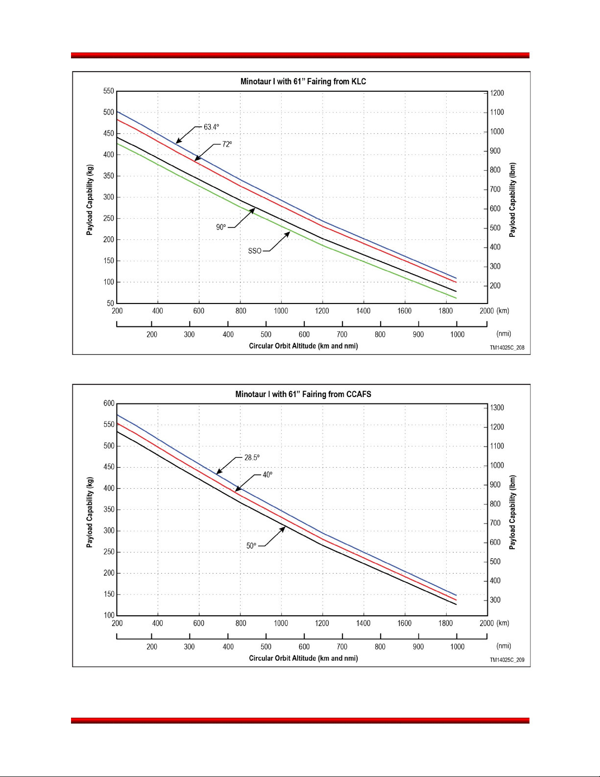
Figure 3.3-5. Minotaur I with 61” Fairing Performance Curves for VAFB Launches
Release 3.0 March 2014 16
Page 30
Minotaur I User’s Guide Section 3.0 – General Performance
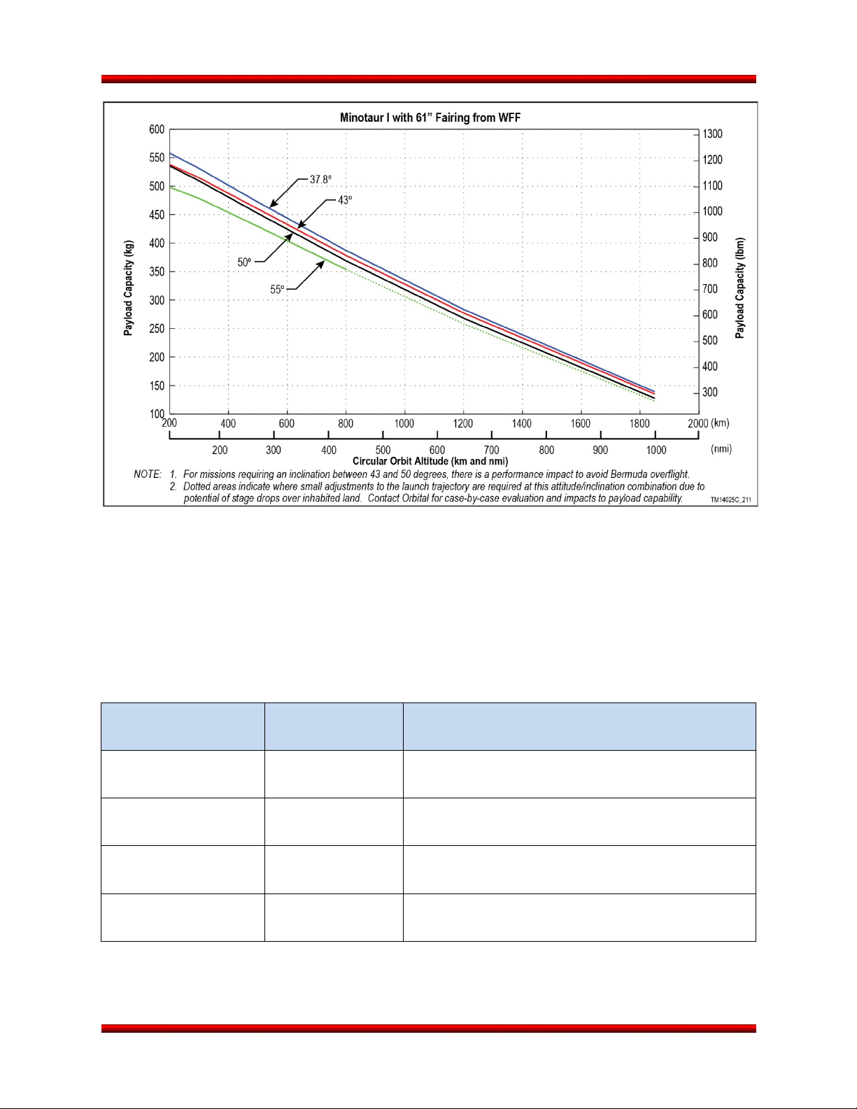
Figure 3.3-6. Minotaur I with 61” Fairing Performance Curves for KLC Launches
Figure 3.3-7. Minotaur I with 61” Fairing Performance Curves for CCAFS Launches
Release 3.0 March 2014 17
Page 31
Minotaur I User’s Guide Section 3.0 – General Performance
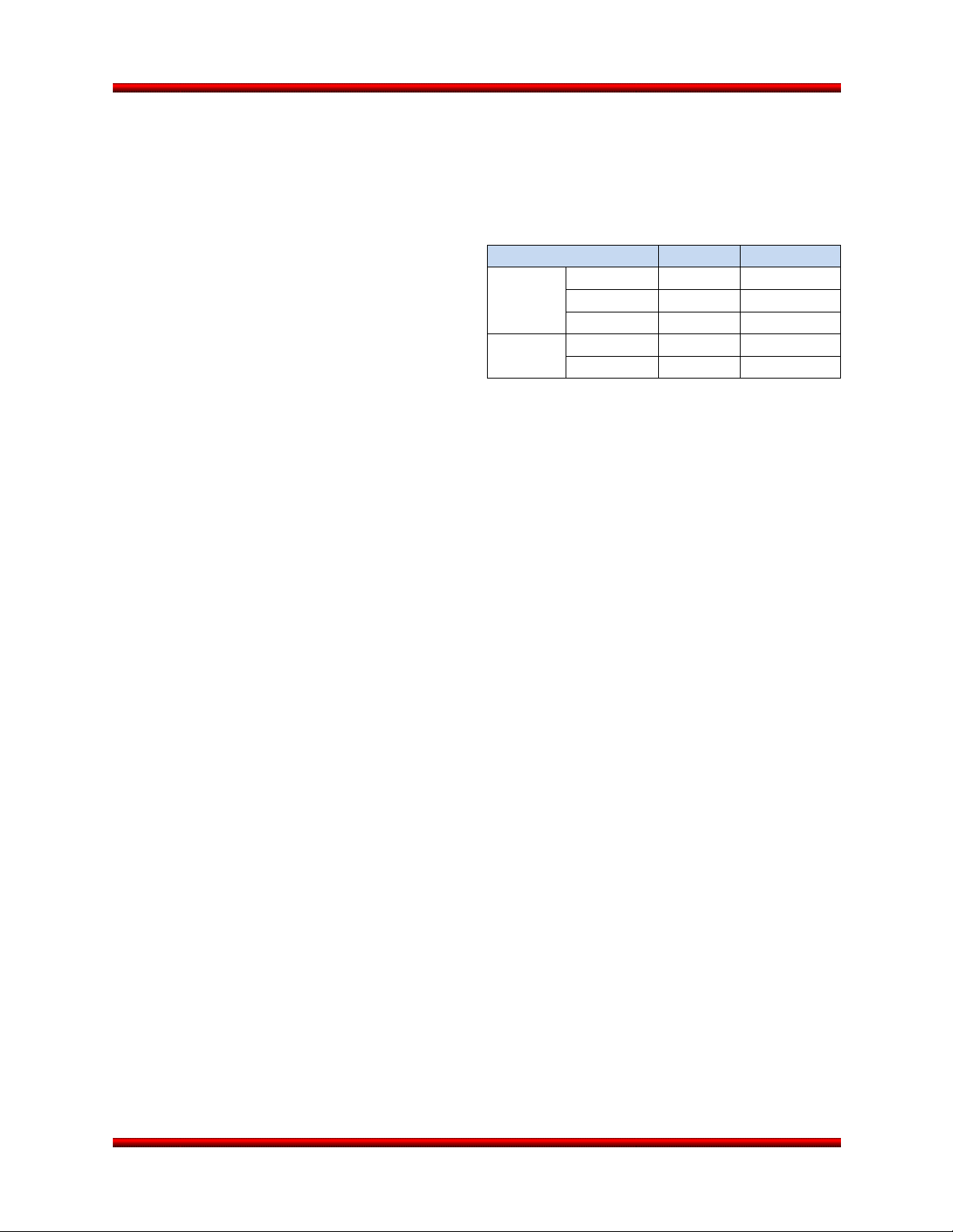
Figure 3.3-8. Minotaur I with 61” Fairing Performance Curves for WFF Launches
3.4. Injection Accuracy
Minotaur I injection accuracy limits are summarized in Table 3.4-1. Better accuracy can likely be provided
depending on specific mission characteristics. For example, heavier payloads will typically have better
insertion accuracy, as will higher orbits. Furthermore, an enhanced option for increased insertion
accuracy is also available (Section 8.9). It utilizes the flight proven Hydrazine Auxiliary Propulsion System
(HAPS) developed on the Pegasus program.
Table 3.4-1. Minotaur I Injection Accuracy
Error Type
Altitude
(Insertion Apse)
Altitude
(Non-Insertion Apse)
Altitude
(Mean)
Inclination ±0.2°
Tolerance
(Worst Case)
±18.5 km (10 nmi)
±92.6 km (50 nmi)
±55.6 km (30 nmi)
Error Source
Stage 4 motor performance uncertainty and guidance
algorithm uncertainty
Stage 4 motor performance and guidance algorithm
uncertainty and navigation (INS) error
Stage 4 motor performance and guidance algorithm
uncertainty and navigation (INS) error
Guidance algorithm uncertainty and navigation
(INS) error
Release 3.0 March 2014 18
Page 32
Minotaur I User’s Guide Section 3.0 – General Performance
Table 3.5-1. Typical Pre-Separation Payload
Error Type
Angle
Rate
Yaw
±1.0°
≤1.0°/sec
Pitch
±1.0°
≤1.0°/sec
Roll
±1.0°
≤1.0°/sec
Spin Axis
±1.0°
≤10 rpm
Spin Rate
--
±3°/sec
3.5. Payload Deployment
Following orbit insertion, the Minotaur I Stage 4 avionics subsystem can execute a series of ACS
maneuvers to provide the desired initial payload attitude prior to separation. This capability may also be
used to incrementally reorient Stage 4 for the
deployment of multiple spacecraft with
independent attitude requirements. Either an
inertially-fixed or spin-stabilized attitude may be
specified by the customer. The maximum spin rate
for a specific mission depends upon the spin axis
moment of inertia of the payload and the amount
of ACS propellant needed for other attitude
maneuvers. Table 3.5-1 provides the typical
payload pointing and spin rate accuracies.
3.6. Payload Separation
Payload separation dynamics are highly dependent on the mass properties of the payload and the
particular separation system utilized. The primary parameters to be considered are payload tip-off and the
overall separation velocity.
Payload tip-off refers to the angular velocity imparted to the payload upon separation due to payload
Center of Gravity (CG) offsets and an uneven distribution of torques and forces. Separation system
options are discussed further in Section 5.2.5. Orbital performs a mission-specific tip-off analysis for each
payload.
Separation velocities are driven by the need to prevent recontact between the payload and the Minotaur I
final stage after separation. The value will typically be 0.6 to 0.9 m/sec (2 to 3 ft/sec).
3.7. Collision/Contamination Avoidance Maneuver
Following orbit insertion and payload separation, the Minotaur final stage will perform a Collision/
Contamination Avoidance Maneuver (C/CAM). The C/CAM minimizes both payload contamination and
the potential for recontact between Minotaur I hardware and the separated payload. Orbital will perform a
recontact analysis for post separation events.
A typical C/CAM begins shortly after payload separation. The launch vehicle performs a 90° yaw
maneuver designed to direct any remaining motor impulse in a direction which will increase the
separation distance between the two bodies. After a delay to allow the distance between the spacecraft
and Stage 4 to increase to a safe level, the launch vehicle begins a “crab-walk” maneuver to impart a
small amount of delta velocity, increasing the separation between the payload and the final stage.
Following the completion of the C/CAM maneuver as described above and any remaining maneuvers,
such as separating other small secondary payloads or downlinking of delayed telemetry data, the ACS
valves are opened and the remaining ACS nitrogen propellant is expelled to meet international space
debris guidelines.
Pointing and Spin Rate Accuracies
3-Axis
Spinning
Release 3.0 March 2014 19
Page 33

Minotaur I User’s Guide Section 4.0 – Payload Environment
4. PAYLOAD ENVIRONMENT
CAUTION
The predicted environments provided in this user's guide are for initial planning
purposes only.
Environments presented here bound a generic mission and should not be used in
mission specific analyses. Mission specific levels are provided as a standard
service and documented or referenced in the mission ICD.
This section provides details of the predicted environmental conditions that the payload will experience
during Minotaur ground operations, powered flight, and launch system on-orbit operations. The predicted
environments provided in this user’s guide are for initial planning purposes only.
Minotaur ground operations include payload integration and encapsulation within the fairing, subsequent
transportation to the launch site and final vehicle integration activities. Powered flight begins at Stage 1
ignition and ends at Stage 4 burnout. Minotaur I post-boost operations begin after Stage 4 burnout and
end following payload separation. To more accurately define simultaneous loading and environmental
conditions, the powered flight portion of the mission is further subdivided into smaller time segments
bounded by critical flight events such as motor ignition, stage separation, and transonic crossover.
The environmental design and test criteria presented have been derived using measured data obtained
from many difference sources, including data from previous flights, motor static fire tests, and other
Orbital system development tests and analyses. These criteria are applicable to Minotaur I configurations
using both the standard 50 in. and optional 61 in. diameter fairing. The predicted levels presented are
intended to be representative of a standard mission. Payload mass, geometry and structural components
vary greatly and will result in significant differences from mission to mission.
Dynamic loading events that occur throughout various portions of the flight include steady state
acceleration, transient low frequency acceleration, acoustic impingement, random vibration, and
pyrotechnic shock events.
4.1. Steady State and Transient Acceleration Loads
Design limit load factors due to the combined effects of steady state and low frequency transient
accelerations are largely governed by payload characteristics. A mission-specific Coupled Loads Analysis
(CLA) will be performed, with customer provided finite element models of the payload, in order to provide
precise load predictions. Results will be referenced in the mission specific ICD. For preliminary design
purposes, Orbital can provide initial CG netloads given a payload’s mass properties, CG location and
bending frequencies.
Release 3.0 March 2014 20
Page 34
Minotaur I User’s Guide Section 4.0 – Payload Environment
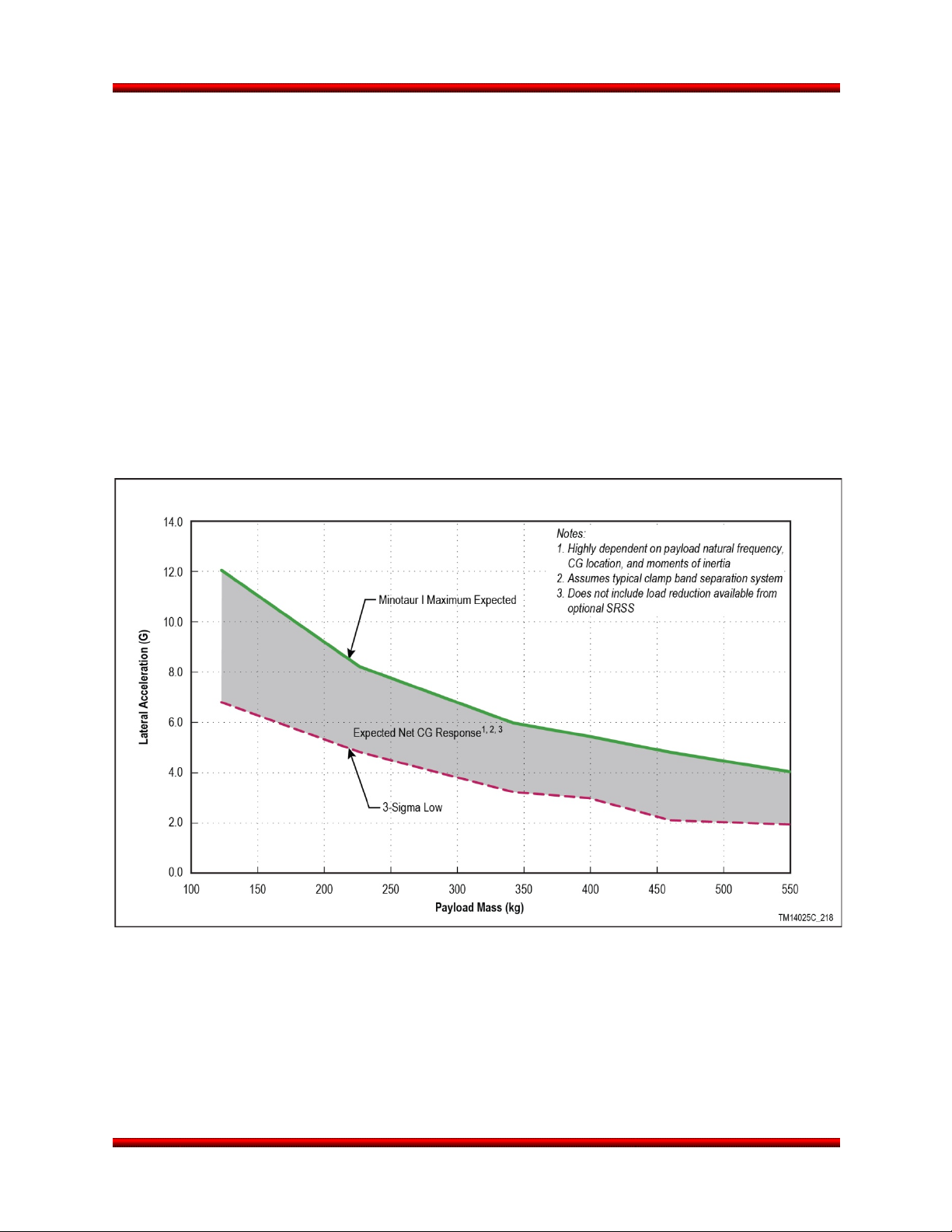
4.1.1. Transient Loads
During upper stage burnout, prior to staging, the transient loads are relatively benign. There are
significant transient loads that occur at both Stage 2 and Stage 3 ignition. During the transient portion of
these ignition events, the steady state axial loads are relatively nonexistent. Transient loads are highly
dependent on payload mass, CG, natural frequencies, and moment of inertias as well as the chosen
separation system and Payload Attach Fitting (PAF). All of these were varied to develop a range of
transient lateral accelerations at the typical dominant event and are shown as a function of payload mass
in Figure 4.1.1-1.
Preliminary and final CLAs will be performed for each Minotaur mission where the payload finite element
model is coupled to the vehicle model. Forcing functions have been developed for all significant flight
events and load cases. Results from the CLA are reported in the Acceleration Transformation Matrix
(ATM) and Load Transformation Matrix (LTM) as requested by the payload provider.
A payload isolation system is available as a non-standard option and is described in Section 8.10. This
system has been demonstrated to significantly reduce transient dynamic loads that occur during flight.
Figure 4.1.1-1. Payload CG Net Transient Lateral Acceleration Envelope
Release 3.0 March 2014 21
Page 35

Minotaur I User’s Guide Section 4.0 – Payload Environment
4.1.2. Steady-State Acceleration
Steady-state vehicle accelerations are determined from the vehicle rigid body analysis. Drag, wind and
motor thrust are applied to a vehicle model. A Monte Carlo analysis is performed to determine variations
in vehicle acceleration due to changes in winds, motor performance and aerodynamics. The steady-state
accelerations must be added to transient accelerations from the CLA to determine the maximum
expected payload acceleration. Maximum steady state accelerations are dependent on the payload mass,
enhancements chosen, and vehicle configuration. The maximum level can potentially occur during either
Stage 3 or 4 burn. Figure 4.1.2-1 depicts the maximum steady-state axial acceleration at burnout for each
stage as a function of payload mass. Lateral steady state accelerations are typically below 0.5 G’s.
Figure 4.1.2-1. Minotaur I 3-Sigma Maximum Axial Acceleration as a Function of Payload Mass
Release 3.0 March 2014 22
Page 36

Minotaur I User’s Guide Section 4.0 – Payload Environment
during Liftoff and Flight
Environment during Flight
4.2. Payload Vibration Environment
The in-flight random vibration curve shown in Figure 4.2-1 encompasses all flight vibration environments.
4.3. Payload Acoustic Environment
The acoustic levels during lift-off and powered flight will not exceed the flight limit levels shown in Figure
4.3-1. If the vehicle is launched over a flame duct, the acoustic levels can be expected to be lower than
shown. This has been demonstrated with flight data.
4.4. Payload Shock Environment
The maximum shock response spectrum at the base of the payload from the launch vehicle will not
exceed the flight limit levels in Figure 4.4-1 (LV to Payload). For missions that utilize an Orbital-supplied
separation system, the maximum expected shock (LV to Payload) will be the level shown for the chosen
separation system. For missions that do not utilize an Orbital-supplied separation system, the maximum
expected shock (LV to Payload) is provided and denoted as "Stage 3/4 Separation Shock at Payload I/F".
For all missions, the shock response spectrum at the base of the payload from payload events should not
exceed the levels in Figure 4.4-2 (Payload to LV). Shock above this level could require requalification of
launch vehicle components.
4.5. Payload Structural Integrity and Environments Verification
The payload must possess sufficient strength,
rigidity, and other characteristics required to
survive the handling and flight load conditions with
margin in a manner that assures both safety and
mission success.
Sufficient payload testing and/or analysis must be
performed to show adequate margin to the
environments and loads specified in Sections 4.1
Figure 4.2-1. Payload Random Vibration
Figure 4.3-1. Payload Acoustic Environment
Release 3.0 March 2014 23
Page 37

Minotaur I User’s Guide Section 4.0 – Payload Environment
through 4.4. The payload design should comply
with the testing and design factors of safety as
found in MIL-HNBK-340A (ref. MIL-STD-1540B)
and NASA GEVS Rev. A, June ‘96. The payload
organization must provide Orbital with a list of the
tests and test levels to which the payload was
subjected prior to payload arrival at the integration
facility.
4.6. Thermal and Humidity Environments
The thermal and humidity environment to which
the payload may be exposed during vehicle
processing and pad operations are defined in the
following sections.
4.6.1. Ground Operations
The payload environment will be maintained by a
Heating, Ventilation, and Air Conditioning (HVAC)
Environmental Control Unit (ECU). The HVAC
Figure 4.4-2. Maximum Shock Environment –
Payload to Launch Vehicle
Figure 4.4-1. Maximum Shock Environment – Launch Vehicle to Payload
Release 3.0 March 2014 24
Page 38

Minotaur I User’s Guide Section 4.0 – Payload Environment
provides conditioned air to the payload in the Payload Processing Facility (PPF) after fairing integration
and on the launch pad. For Minotaur I, conditioned air is not provided during transport and lifting
operations. The conditioned air enters the fairing at a location forward of the payload, exits aft of the
payload and is maintained up to 5 minutes prior to launch (for the 61” fairing, the conditioned air can be
maintained until liftoff). A diffuser is designed into the air conditioning inlet to reduce impingement
velocities on the payload. Class 10,000 (ISO 7) can be provided inside a clean room and at payload
fairing HVAC inlet on a mission-specific basis as an enhanced option (Section 8.6).
Fairing inlet conditions are selected by the customer, and are bounded as follows:
a. Dry Bulb Temperature: 13 to 29 °C (55 to 85 °F) controllable to ±5 °C (±10 °F) of setpoint
b. Temperature environment lower limit is 12.8 °C (55 °F) due to the Orion 38 motor’s limit
c. Standard Setpoint: 18.3 °C (65 °F)
d. Dew Point Temperature: 3 to 17 °C (38 to 62 °F)
e. Relative Humidity: determined by drybulb and dew point temperature selections and generally
controlled to within ±15%. Relative humidity is bound by the psychrometric chart and will be
controlled such that the dew point within the fairing is never reached.
f. Nominal Flow: 11.3 m
A diagram of the HVAC system is shown in Figure 4.6.1-1.
3
/min (400 cfm)
Figure 4.6.1-1. Minotaur I HVAC System Provides Conditioned Air to the Payload
4.6.2. Powered Flight
The maximum fairing inside wall temperature will be maintained at less than 93 °C (200 °F), with an
emissivity of 0.92 in the region of the payload. As a non-standard service, a low emissivity coating can be
applied to reduce emissivity to less than 0.1. Interior surfaces aft of the payload interface will be
maintained at less than 121 °C (250 °F). This temperature limit envelopes the maximum temperature of
any component inside the payload fairing with a view factor to the payload with the exception of the Stage
4 motor. The maximum Stage 4 motor surface temperature exposed to the payload will not exceed 177
°C (350 °F), assuming no shielding between the aft end of the payload and the forward dome of the motor
assembly. Whether this temperature is attained prior to payload separation is dependent upon mission
timeline.
Release 3.0 March 2014 25
Page 39
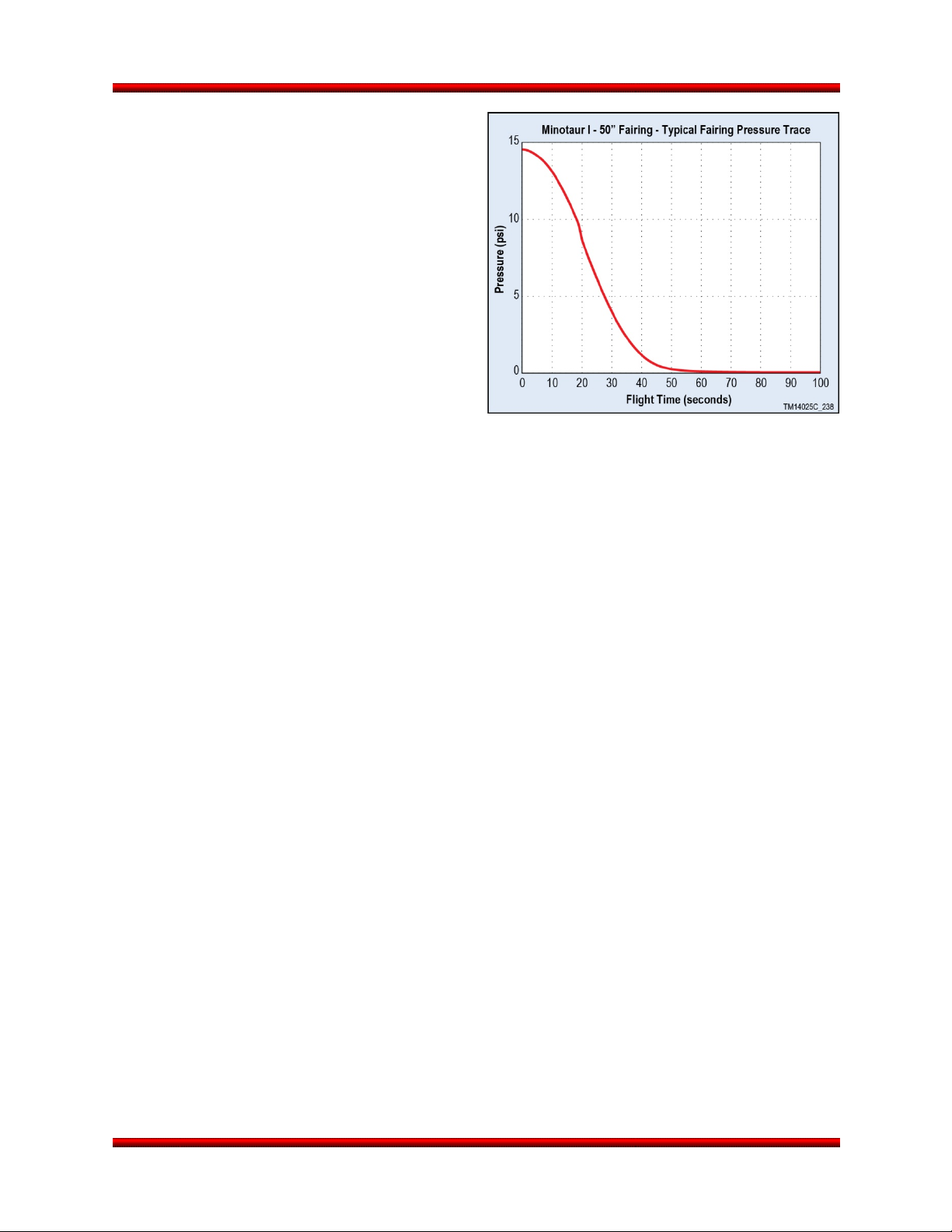
Minotaur I User’s Guide Section 4.0 – Payload Environment
The fairing peak vent rate is typically less than 0.6
psi/sec. Fairing deployment will be initiated at a
time in flight that the maximum dynamic pressure
is less than 0.01 psf or the maximum free
molecular heating rate is less than 1135 W/m
2
BTU/ft
/sec), as required by the payload.
4.6.3. Nitrogen Purge (non-standard service)
If required for spot cooling of a payload
component, Orbital will provide GN
localized regions in the fairing as a non-standard
service. This option is discussed in more detail in
Section 8.3.
4.7. Payload Contamination Control
All payload integration procedures, and Orbital’s
contamination control program have been
designed to minimize the payload’s exposure to contamination from the time the payload arrives at the
payload processing facility through orbit insertion and separation. The payload is fully encapsulated within
the fairing at the payload processing facility, assuring the payload environment stays clean in a Class
100,000 environment. Launch vehicle assemblies that affect cleanliness within the encapsulated payload
volume include the fairing, avionics assembly, Stage 4 assembly, and 3/4 Interstage. These assemblies
are cleaned such that there is no particulate or non-particulate matter visible to the normal unaided eye
when inspected from 2 to 4 feet under 50 ft-candle incident light (Visibly Clean Level II). After
encapsulation, the fairing envelope is either sealed or maintained with a positive pressure, Class 100,000
(ISO 8) continuous purge of conditioned air.
If required, the payload can be provided with enhanced contamination control as an option, providing a
Class 10,000 (ISO 7) environment, low outgassing, and Visibly Clean Plus Ultraviolet cleanliness. With
the enhanced contamination control option, the Orbital-supplied elements will be cleaned and controlled
to support a Class 10,000 clean room environment, as defined in ISO 14644-1 clean room standards
(ISO 7). This includes limiting volatile hydrocarbons to maintain hydrocarbon content at less than 15 ppm.
Also with the enhanced contamination control option, the ECU continuously purges the fairing volume
with clean filtered air and maintains humidity between 30 to 60 percent. Orbital’s ECU incorporates a
HEPA filter unit to provide ISO 7 (Class 10,000) air. Orbital monitors the supply air for particulate matter
via a probe installed upstream of the fairing inlet duct prior to connecting the air source to the payload
fairing.
4.8. Payload Electromagnetic Environment
The payload Electromagnetic Environment (EME) results from two categories of emitters: Minotaur I
onboard antennas and Range radar. All power, control and signal lines inside the payload fairing are
shielded and properly terminated to minimize the potential for Electromagnetic Interference (EMI). The
Minotaur I payload fairing is Radio Frequency (RF) opaque, which shields the payload from most external
RF signals while the payload is encapsulated. Details of the analysis can be provided upon request.
2
(0.1
2
flow to
Figure 4.6.2-1. Typical Minotaur I Fairing
Pressure Profile
Release 3.0 March 2014 26
Page 40

Minotaur I User’s Guide Section 4.0 – Payload Environment
Table 4.8-1 lists the frequencies and maximum radiated signal levels from vehicle antennas that are
located near the payload during ground operations and powered flight. Antennas located inside the fairing
are inactive until after fairing deployment. The specific EME experienced by the payload during ground
processing at the VAB and the launch site will depend somewhat on the specific facilities that are utilized
as well as operational details. However, typically the field strengths experienced by the payload during
ground processing with the fairing in place are controlled procedurally and will be less than 2 V/m from
continuous sources and less than 10 V/m from pulse sources. Range transmitters are typically controlled
to provide a field strength of 10 V/m or less. This EME should be compared to the payload’s RF
susceptibility levels (MIL-STD-461, RS03) to define margin.
Table 4.8-1. Minotaur I Launch Vehicle RF Emitters and Receivers
Source 1 2 3 4 5 6 7
Enhanced
Function
Receive/Transmit Receive Transmit Receive Transmit Transmit Transmit Receive
Band UHF C-band C-band S-band S-band S-band
Frequency (MHz) 421.0 5765 5690 2288.5 2269.5 2241.5
Bandwidth N/A 14 MHz 14 MHz 1.78 MHz 1.78 MHz 256 kHz
Power Output N/A 400 W (peak) N/A 10 W 10 W 5 W N/A
Sensitivity -107 dBm -70 dBm -70 dBm N/A N/A N/A -123 dB,
Modulation Tone Pulse Code Pulse Code PCM/FM PCM/FM PCM/FM
Field Strength at
PL Interfaces
Command
Destruct
N/A
Tracking
Transponder
3.016 V/m Average
67.436 V/m per 0.5 µsec
Tracking
Transponder
Launch
Vehicle
Instrumentation
Telemetry
(Optional)
<100 V/m <60 V/m N/A
GPB GPB
L-band
(L1/L2)
1575.42 /
1227.6
20.46 MHz
(P(Y) Code)
Spread
Spectrum
QPSK
Release 3.0 March 2014 27
Page 41

Minotaur I User’s Guide Section 5.0 – Payload Interfaces
5. PAYLOAD INTERFACES
This section describes the available mechanical, electrical and Launch Support Equipment (LSE)
interfaces between the Minotaur I launch vehicle and the payload.
5.1. Payload Fairing
5.1.1. 50” Standard Minotaur I Fairing
The standard payload fairing consists of two graphite composite halves, with a nosecap bonded to one of
the halves, and a separation system. Each composite half is composed of a cylinder and an ogive
section. The two halves are held together by two titanium straps, both of which wrap around the cylinder
section, one near its midpoint and one just aft of the ogive section. Additionally, an internal retention bolt
secures the two fairing halves together at the surface where the nosecap overlaps the top surface of the
other fairing half. The base of the fairing is separated using a frangible joint. During Flight, fairing
separation involves first initiating the separation nut which releases the internal retention bolt at the nose
of the fairing, then initiating bolt cutters which release the two titanium straps. Next, the frangible joint is
severed which allows each half of the fairing to then rotate on hinges mounted on the Stage 3 side of the
interface. A contained hot gas generation system is used to drive pistons that force the fairing halves
open. All fairing deployment systems are non-contaminating.
5.1.1.1. Payload Dynamic Design Envelope
The fairing drawing in Figure 5.1.1.1-1 shows the maximum dynamic envelopes available for the payload
during powered flight. The dynamic envelopes shown account for fairing and vehicle structural deflections
only. The payload contractor must take into account deflections due to spacecraft design and
manufacturing tolerance stack-up within the dynamic envelope. Proposed payload dynamic envelope
violations must be approved by Orbital via the ICD.
No part of the payload may extend aft of the payload interface plane without specific Orbital approval.
These areas are considered stay out zones for the payload and are shown in Figure 5.1.1.1-1. Incursions
to these zones may be approved on a case-by-case basis after additional verification that the incursions
do not cause any detrimental effects. Vertices for payload deflection must be given with the Finite
Element Model to evaluate payload dynamic deflection with the CLA. The payload contractor should
assume that the interface plane is rigid; Orbital has accounted for deflections of the interface plane. The
CLA will provide final verification that the payload does not violate the dynamic envelope.
Release 3.0 March 2014 28
Page 42

Minotaur I User’s Guide Section 5.0 – Payload Interfaces
Figure 5.1.1.1-1. 50” Payload Fairing Dynamic Envelope with
38” (97 cm) Diameter Payload Interface
5.1.2. Optional 61” Payload Fairing
To fit payloads larger than those that can be accommodated by the standard 50” diameter fairing, a larger
61” diameter fairing is available as an enhancement. This structure uses an innovative diffusion-bonded
titanium sandwich panel composed of titanium facesheets and titanium honeycomb core. The 61”
diameter titanium fairing, along with its separation and deployment system, is qualified for flight and has
flown successfully on previous Minotaur I missions. Impacts to performance when compared to the 50”
fairing are negligible as a result of the more aerodynamic bi-conic nose.
5.1.2.1. Payload Dynamic Design Envelope (61” Payload Fairing)
Figure 5.1.2.1-1 shows the maximum dynamic envelopes available for the payload during powered flight
within the optional 61” payload fairing. The dynamic envelopes shown account for fairing and vehicle
structural deflections only. The payload contractor must take into account deflections due to spacecraft
design and manufacturing tolerance stack-up within the dynamic envelope. Proposed payload dynamic
envelope violations must be approved by Orbital via the ICD.
Release 3.0 March 2014 29
Page 43
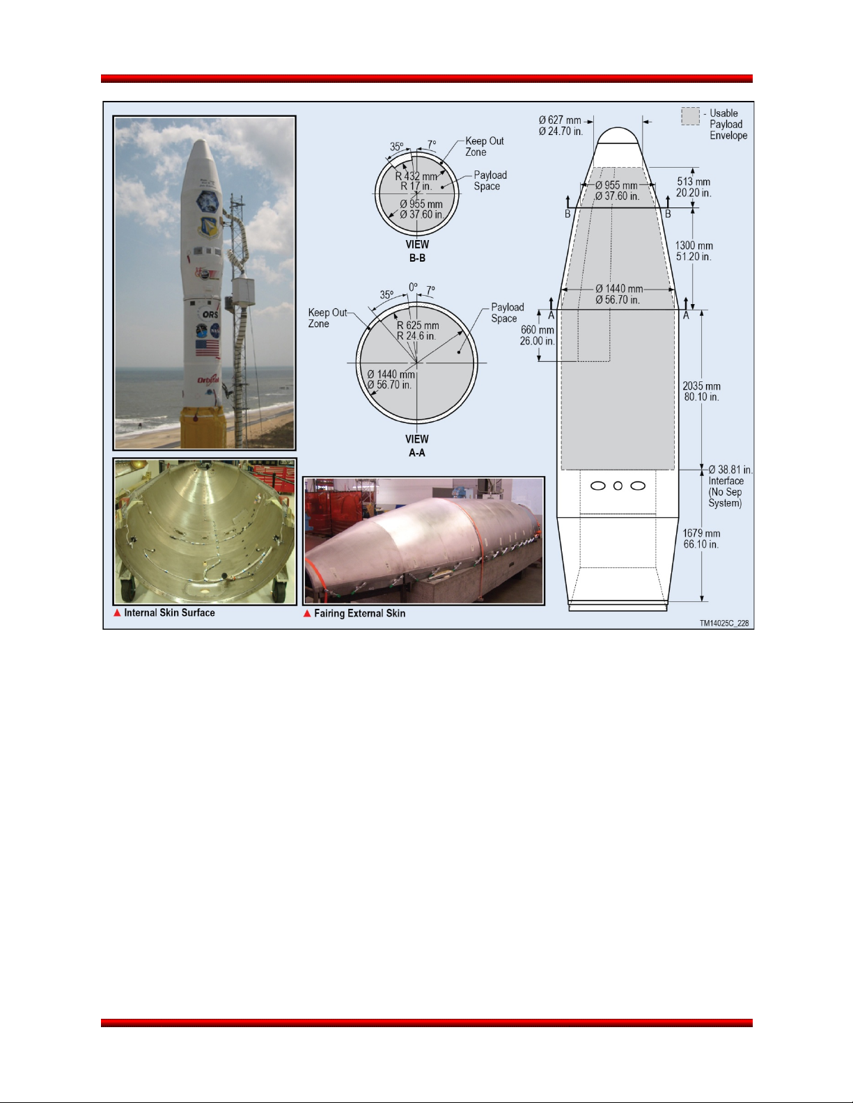
Minotaur I User’s Guide Section 5.0 – Payload Interfaces
Figure 5.1.2.1-1. 61” Payload Fairing Dynamic Envelope with
38” (97 cm) Diameter Payload Interface
No part of the payload may extend aft of the payload interface plane without specific Orbital approval.
Incursions to these zones may be approved on a case-by-case basis after additional verification that the
incursions do not cause any detrimental effects. Vertices for payload deflection must be given with the
Finite Element Model to evaluate payload dynamic deflection with the CLA. The payload contractor
should assume that the interface plane is rigid; Orbital has accounted for deflections of the interface
plane. The CLA will provide final verification that the payload does not violate the dynamic envelope.
5.1.3. Payload Access Door
On the standard 50” fairing, Orbital provides one 254 mm by 368 mm (10.00 in. by 14.50 in.) payload
fairing access door to provide access to the payload after fairing mate. The door can be positioned
according to user requirements within the zone defined in Figure 5.1.3-1. The position of the payload
fairing access door must be defined no later than L-8 months. Additional access doors can be provided as
a non-standard service (see Section 8.4). Access doors on the optional 61” fairing are limited to 254 mm
by 279 mm (10.00 in. by 11.00 in.) and can be positioned within the zone defined in Figure 5.1.3-2.
Release 3.0 March 2014 30
Page 44

Minotaur I User’s Guide Section 5.0 – Payload Interfaces
Figure 5.1.3-1. 50” Payload Fairing Access Door Placement Zone
Release 3.0 March 2014 31
Page 45

Minotaur I User’s Guide Section 5.0 – Payload Interfaces
Figure 5.1.3-2. 61” Payload Fairing Access Door Placement Zone
5.2. Payload Mechanical Interface and Separation System
Minotaur I provides for a standard non-separating payload interface and several optional Orbital-provided
payload separation systems. Orbital will provide all flight hardware and integration services necessary to
attach non-separating and separating payloads to Minotaur I. Ground handling equipment is typically the
responsibility of the payload contractor. All attachment hardware, whether Orbital or customer provided,
must contain locking features consisting of locking nuts, inserts or fasteners. Additional mechanical
interface diameters and configurations can readily be provided as an enhanced option.
5.2.1. Minotaur Coordinate System
The Minotaur I Launch Vehicle coordinate system is defined in Figure 5.2.1-1. For clocking references,
degree marks are clockwise when aft looking forward. The positive X-axis is forward along the vehicle
longitudinal centerline, the positive Z axis is along the 180 deg angular azimuth, and the positive Y axis is
along the 90 deg angular azimuth, and completes the orthogonal system. The origin of the LV coordinate
system is centered at the Stage 1 nozzle exit plane of the LV and the vehicle centerline (X = 0.0 in, Y =
0.0 in, Z = 0.0 in).
Release 3.0 March 2014 32
Page 46

Minotaur I User’s Guide Section 5.0 – Payload Interfaces
Figure 5.2.1-1. Minotaur Coordinate System
Release 3.0 March 2014 33
Page 47

Minotaur I User’s Guide Section 5.0 – Payload Interfaces
Diameter Payload Mechanical Interface
5.2.2. Orbital Supplied Mechanical Interface Control Drawing
Orbital will provide a toleranced Mechanical
Interface Control Drawing (MICD) to the payload
contractor to allow accurate machining of the
fastener holes. The Orbital provided MICD is the
only approved documentation for drilling the
payload interface.
5.2.3. Standard Non-Separating Mechanical Interface
Orbital’s payload interface design provides a
standard interface that will accommodate multiple
payload configurations. The Minotaur I baseline is
for payloads that provide their own separation
system and payloads that will not separate. The
standard interface is a 986 mm (38.81 in.) diameter
bolted interface. A butt joint with 60 holes (0.281 in. diameter) designed for ¼” fasteners is the payload
mounting surface as shown in Figure 5.2.3-1.
The Minotaur I avionics section is designed to accommodate a 680 kg (1500 lbm) payload with a CG 762
mm (30 in.) above the fixed interface flange. Therefore, as an initial guideline, payload mass times its CG
location above this fixed interface needs to be less than or equal to a mass moment of 51,820 kg-cm
(45,000 lbm-in.). The payload mass and CG location must include the Payload Attach Fitting (PAF)
hardware (adapter cone, separation system, isolation system, etc.), in addition to the actual spacecraft
mass properties.
5.2.4. Optional Mechanical Interface
Alternate or multiple payload configurations can be accommodated with the use of a variety of payload
adapter fittings. Minotaur I launch vehicles allow flexibility in mounting patterns and configurations.
5.2.4.1. Dual and Multi Payload Adapter Fittings
The Minotaur launch vehicle design flexibility and performance readily accommodates multiple spacecraft
that are independently deployed when required as a non-standard service. Minotaur I has demonstrated
multiple payload adapter systems, such as the JAWSAT mission, which successfully deployed five
satellites and six picosats, as well as load bearing satellites such as the COSMIC mission, which
successfully deployed six independent spacecraft.
5.2.4.1.1. Load-Bearing Spacecraft
Use of load-bearing spacecraft maximizes use of available volume and mass. In this case, the aft loadbearing spacecraft interfaces directly to the avionics assembly interface and to the forward spacecraft via
pre-determined spacecraft to spacecraft interfaces.
The requirements levied upon spacecraft in this scenario are those involving mechanical and electrical
compatibility with the interfacing spacecraft as well as the launch vehicle. Structural loads from forward
satellites during all flight events must be transmitted through the aft satellites to the Minotaur I. Orbital will
Figure 5.2.3-1. Standard, Non-separating 38.81”
Release 3.0 March 2014 34
Page 48

Minotaur I User’s Guide Section 5.0 – Payload Interfaces
provide LV minimum structural interface design
criteria for shear, bending moment, axial and
lateral loads, and stiffness.
Another available approach involves the use of a
spacecraft design using the Orbital MicroStar bus
which was successfully developed and flown for
ORBCOMM. The MicroStar bus features a circular
design with an innovative, low-shock separation
system. The spacecraft bus is designed to allow
stacking of co-manifested payloads in “slices”
within the fairing. The bus design is compact and
provides exceptional lateral stiffness. This
approach was flown on the COSMIC mission and
is shown in Figure 5.2.4.1.1-1.
To avoid the complications involved in spacecraft
to spacecraft interfaces and loads, Orbital can
provide a mission unique Multi-Payload Adapter
(MPA). An example of this approach was flown on
the JAWSAT mission, in which the primary payload
(JAWSAT) was a Multiple Payload Adapter (MPA)
from which four small satellites were separated
(Figure 5.2.4.1.1-2). After separating the smaller
“piggyback” satellites, the JAWSAT MPA was also
separated as an autonomous satellite by utilizing
the Orbital 23” separation system and adapter
cone. An updated concept to provide greater
payload options and primary payload volume (by
mounting directly to the avionics assembly without
a separate PAF) is shown in Figure 5.2.4.1.1-3.
For each of these options, integrated coupled loads
analyses will be performed with test verified math models provided by the spacecrafts/payloads. These
analyses are required to verify the fundamental frequency and deflections of the stack for compliance with
the Minotaur I requirements. Design criteria provided by Orbital will include “stack” margins to minimize
interactive effects associated with potential design changes of each spacecraft. Orbital will provide the
necessary engineering coordination between the SV and LV.
5.2.4.1.2. Non Load-Bearing Spacecraft – Dual Payload Adapter Fitting (DPAF)
The Minotaur I DPAF option supports delivery of two independent spacecraft to orbit (Figure 5.2.4.1.2-1).
The lower payload is encompassed inside the 50” DPAF structure. This configuration assumes use of the
Minotaur I 61” fairing that has the available envelope to support a large upper spacecraft and the 50”
DPAF structure. The design of the DPAF incorporates a light weight graphite structure which provides
independent load paths for each satellite. The upper spacecraft loads are transmitted around the lower
spacecraft via the DPAF structure, thus avoiding any structural interface between the two payloads. The
Figure 5.2.4.1.1-1. COSMIC Spacecraft
Configuration Utilized the Orbital MicroStar Bus
to Fly Six SVs
Figure 5.2.4.1.1-2. JAWSAT Multiple Payload
Adapter Load Bearing Spacecraft
Release 3.0 March 2014 35
Page 49

Minotaur I User’s Guide Section 5.0 – Payload Interfaces
structure that supports the dual payload
configuration includes a 50” cylindrical section that
is configurable in height depending on payload
unique requirements. The primary payload is
mounted to the top of this DPAF structure using a
38.8” separation system. The lower payload
resides within the DPAF structure during flight
through primary payload deployment. After the
primary payload is deployed, the DPAF structure is
released using a separation system that reveals
the secondary payload. The secondary payload is
released using a 38.8” separation system at the
38.8” interface or via a smaller separation system
mounted to a payload adaptor cone. As spacecraft
have many options in separation systems that are
available to support a given mission, both primary
and secondary payload release mechanisms are
not included in this enhancement as they are
addressed in Section 8.1.
5.2.5. Optional Separation Systems
Three separation system options are offered as
flight proven enhancements for Minotaur I. All
systems are configurable to various interface
diameters and have extensive flight history. These
separation systems include the Orbital marmon
clamp band system, Planetary Systems Corp.
Motorized Lightband (MLB) System, and RUAG
low-shock marmon clamp band system. Through
this enhancement, Orbital procures the qualified
separation system hardware, conducts separation
testing and analyses, and integrates the system
onto the launch vehicle. The separation system
options are summarized in Table 5.2.5-1.
The primary separation parameters associated
with a separation system are SV tip-off and overall
separation velocity. SV tip-off refers to the angular
velocity imparted to the SV upon separation due to
SV CG offsets and an uneven distribution of
torques and forces. SV tip-off rates induced by the
separation systems presented are generally under
1 deg/sec per axis. Entering into the SV separation
phase, the launch vehicle reduces vehicle rates.
The combined tip-off rate of the separation system
and launch vehicle is generally less than 2 deg/sec
about each axis when spacecraft mass CG offsets
Figure 5.2.4.1.1-3. Five Bay Multiple Payload
Adapter Concept
Figure 5.2.4.1.2-1. DPAF Configuration
Release 3.0 March 2014 36
Page 50
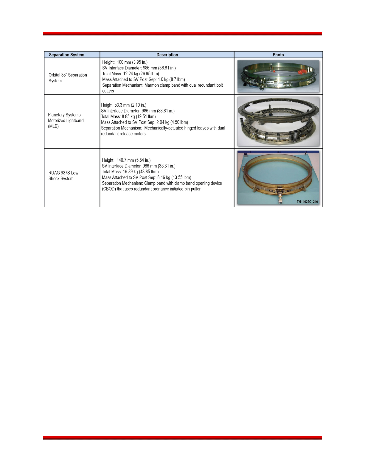
Minotaur I User’s Guide Section 5.0 – Payload Interfaces
Table 5.2.5-1. Minotaur I Separation System Options
are within specified limits presented in Section 5.4.1. Separation velocities are usually optimized to
provide the SV with the lowest separation velocity while ensuring recontact does not occur between the
SV and the Minotaur upper stage after separation. The spacecraft is deployed by matched push-off
springs with sufficient energy to produce the required relative separation velocity to prevent re-contact
with the LV. If non-standard separation velocities are needed, alternative springs may be substituted on a
mission-specific basis as a non-standard service. SV separation dynamics are highly dependent on the
mass properties of the SV and the particular separation system utilized. Typical separation velocity is 0.6
to 0.9 m/sec (2 to 3 ft/sec). As a standard service, Orbital performs a mission-specific tip-off and
separation analyses for each SV.
5.2.5.1. Orbital 38” Separation System
The flight proven Orbital 38” separation system, Figure 5.2.5.1-1, is composed of two rings connected by
a marmon clamp band which is separated by redundant bolt cutters. This system has flown successfully
on over twenty Orbital launch vehicle missions to date. The weight of hardware separated with the SV is
approximately 4.0 kg (8.7 lbm). Orbital-provided attachment bolts to this interface can be inserted from
either the launch vehicle or the SV side of the interface via the through-holes in the separation system
flange (NAS630xU, fastener length based on SV flange thickness).
In addition to the 38” configuration, Orbital has flight qualified 23” and 17” separation systems. Each of
these three systems is based on the marmon clamp band design.
Release 3.0 March 2014 37
Page 51

Minotaur I User’s Guide Section 5.0 – Payload Interfaces
Figure 5.2.5.1-1. Orbital 38” Separation System
Release 3.0 March 2014 38
Page 52

Minotaur I User’s Guide Section 5.0 – Payload Interfaces
5.2.5.2. Planetary Systems Motorized Lightband (MLB)
The Planetary Systems MLB, Figure 5.2.5.2-1, provides a fully qualified and flight proven low shock and
lightweight option for use on Minotaur missions. Multiple sizes of MLBs have previously flown on Minotaur
vehicles. The MLB uses a system of mechanically-actuated hinged leaves, springs, and a dual redundant
release motor to separate the upper ring (mounted to the spacecraft) from the lower ring. The MLB is
flexible and configurable to support various
separation force requirements and number of
required separation connectors. The MLB upper
ring interfaces to the spacecraft through holes in
the upper ring and remains attached after
separation adding approximately 2.04 kg (4.5 lb)
of mass. Due to the unique design of the system
and space constraints for tooling, Orbital provided
socket head cap screw mating hardware must be
inserted from the launch vehicle side. The MLB
offers the unique ability to perform separation
verification tests both at a component and system
level.
5.2.5.3. RUAG 937 Separation Systems
The RUAG 937S 38” separation system, Figure
5.2.5.3-1, is a flight proven, low-shock separation
system that offers outstanding load capability. This
system is composed of two rings and a clamp
band separated by a Clamp Band Opening Device
(CBOD) rather than traditional bolt cutters. The
CBOD uses a redundant, ordnance initiated pin
puller device to convert strain energy, created by
the clamp band tension, into kinetic energy
through a controlled event that greatly reduces
separation shock. Hardware separated with the
payload is approximately 6.2 kg (13.6 lb) for the
937S. Orbital-provided attachment bolts to this
interface can be inserted from either the launch
vehicle or the SV side of the interface.
Figure 5.2.5.2-1. 38” Planetary Sciences
Motorized Lightband
Figure 5.2.5.3-1. RUAG 937S 38”
Separation System
Release 3.0 March 2014 39
Page 53

Minotaur I User’s Guide Section 5.0 – Payload Interfaces
5.3. Payload Electrical Interfaces
The payload electrical interface, shown in Figure 5.3-1, supports battery charging, external power,
discrete commands, discrete telemetry, analog telemetry, serial communication, SV separation
indications, and up to 16 separate ordnance discretes. If an optional Orbital-provided separation system
is utilized, Orbital will provide all the wiring through the separable interface plane. If the option is not
exercised the spacecraft will be responsible to provide the separation connectors and wiring through the
separation plane.
Figure 5.3-1. Payload Electrical Interface Block Diagram Payload Interface Circuitry
5.3.1. Payload Umbilical Interfaces
One dedicated payload umbilical is provided with 60 circuits from the ground to the spacecraft. This
umbilical is a dedicated pass through harness for ground processing support. This umbilical allows the SV
command, control, monitor, and power to be easily configured per each individual user’s requirements.
The umbilical wiring is configured as a one-to-one from the Payload/Minotaur interface through to the
payload EGSE interface in the Launch Equipment Vault, the closest location for operating customer
supplied EGSE equipment. The length of the internal umbilical is approximately 13.7 m (45 ft). The length
of the external umbilical from the LEV/SEB to the launch vehicle is approximately 35.1 m (115 ft) to 96.0
m (315 ft) depending on the launch site chosen for the mission.
Figure 5.3.1-1 details the pin outs for the standard interface umbilical. All wires are twisted, shielded
pairs, and pass through the entire umbilical system, both vehicle and ground, as one-to-one to simplify
and standardize the payload umbilical configuration requirements while providing maximum operational
flexibility to the payload provider.
Release 3.0 March 2014 40
Page 54

Minotaur I User’s Guide Section 5.0 – Payload Interfaces
Figure 5.3.1-1. Payload Umbilical 1:1 Pin Outs
5.3.2. Payload Interface Circuitry
Standard interface circuitry passing through the payload-to-launch vehicle electrical connections are
shown in Figure 5.3-1. This figure details the interface characteristics for launch vehicle commands,
discrete and analog telemetry, separation loopbacks, pyro initiation, and serial communications interfaces
with the launch vehicle avionics systems.
5.3.3. Payload Battery Charging
Orbital provides the capability for remote controlled charging of payload batteries, using a customer
provided battery charger. This power is routed through the payload umbilical cable. Up to 5.0 amperes
per wire pair can be accommodated. The payload battery charger should be sized to withstand the line
loss from the LEV to the spacecraft.
5.3.4. Payload Command and Control
The Minotaur standard interface provides discrete sequencing commands generated by the launch
vehicle’s Ordnance Driver Module (ODM) that are available to the payload as closed circuit opto-isolator
command pulses of 5 A in lengths of 35 ms minimum. The total number of ODM discretes is sixteen (16)
and can be used for any combination of (redundant) ordnance events and/or discrete commands
depending on the SV requirements.
5.3.5. Pyrotechnic Initiation Signals
Orbital provides the capability to directly initiate 16 separate pyrotechnic conductors through two
dedicated MACH ODMs. Each ODM provides for up to eight drivers capable of a 5 A, 100 ms, current
limited pulse into a 1.5 ohm resistive load. All eight channels can be fired simultaneously with an
accuracy of 1 ms between channels. In addition, the ODM channels can be utilized to trigger high
impedance discrete events if required. Safing for all SV ordnance events will be accomplished either
through an Arm/Disarm (A/D) Switch or Safe Plugs.
5.3.6. Payload Telemetry
The baseline telemetry subsystem capability provides a number of dedicated payload discrete (bi-level)
and analog telemetry monitors through dedicated channels in the vehicle encoder. Up to 24 channels will
be provided with type and data rate being defined in the mission requirements document. The SV serial
and analog data will be embedded in the baseline vehicle telemetry format. For discrete monitors, the SV
must provide the 5 Vdc source and the return path. The current at the payload interface must be less than
Release 3.0 March 2014 41
Page 55

Minotaur I User’s Guide Section 5.0 – Payload Interfaces
10 mA. Separation breakwire monitors can be specified if required. The number of analog channels
available for payload telemetry monitoring is dependent on the frequency of the data. Payload telemetry
requirements and signal characteristics will be specified in the Payload ICD and should not change once
the final telemetry format is released at approximately L-6 months. Orbital will record, archive, and reduce
the data into a digital format for delivery to the payloaders for review.
Due to the use of strategic assets, Minotaur I telemetry is subject to the provisions of the START treaty.
These provisions require that certain Minotaur I telemetry be unencrypted and provided to the START
treaty office for dissemination to the signatories of the treaty. The extent to which START applies to the
payload telemetry will be determined by SD. Encrypted payload telemetry can be added as a nonstandard service pending approval by SD and the START treaty office.
5.3.7. Payload Separation Monitor Loopbacks
Separation breakwire monitors are required on both sides of the payload separation plane. With the
Orbital provided separation systems, Minotaur I provides three separation loopbacks on the launch
vehicle side of the separation plane for positive payload separation indication.
It is a Launch Vehicle requirement that the payload provide two separation loopback circuits on the
payload side of the separation plane. These are typically wired into different separation connectors for
redundancy. These breakwires are used for positive separation indication telemetry and initiation of the
C/CAM maneuver.
5.3.8. Telemetry Interfaces
The standard Minotaur I payload interface provides a 16Kbps RS-422/RS-485 serial interface for payload
use with the flexibility to support a variety of channel/bit rate requirements, and provide signal
conditioning, PCM formatting (programmable) and data transmission bit rates. The number of channels,
sample rates, etc. will be defined in the Payload ICD.
5.3.9. Non Standard Electrical Interfaces
Non-standard services such as serial command and telemetry interfaces can be negotiated between
Orbital and the payload provider on a mission-by-mission basis. The selection of the separation system
could also impact the payload interface design and will be defined in the Payload ICD.
5.3.10. Electrical Launch Support Equipment
Orbital will provide space for a rack of customer supplied EGSE in the LCR, and/or the on-pad Launch
Equipment Vault (LEV). The equipment will interface with the launch vehicle/spacecraft through either the
dedicated payload umbilical interface or directly through the payload access door. The payload customer
is responsible for providing cabling from the EGSE location to the launch vehicle/spacecraft.
Separate payload ground processing harnesses that mate directly with the payload can be
accommodated through the payload access door(s) as defined in the Payload ICD.
Release 3.0 March 2014 42
Page 56
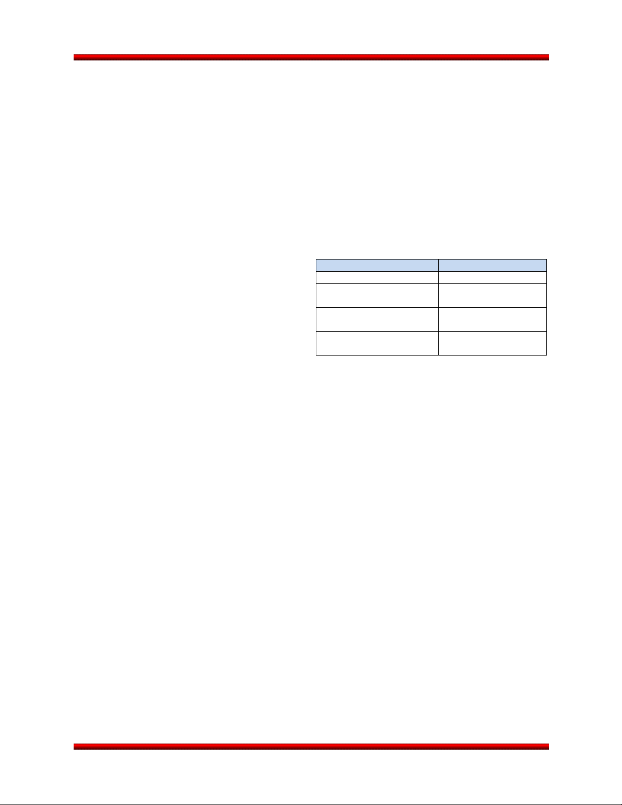
Minotaur I User’s Guide Section 5.0 – Payload Interfaces
Table 5.4.2-1. Payload Mass Properties
Measurement
Accuracy
Mass
±0.5%
Principal Moments of
Inertia
±2.7 kg – m2
(±2.0 sl – ft2)
Center of Gravity X, Y,
and Z Axes
±6.4 mm
(±0.25 in.)
5.4. Payload Design Constraints
The following sections provide design constraints to ensure payload compatibility with the Minotaur I
launch vehicle.
5.4.1. Payload Center of Mass Constraints
Along the Y and Z axes, the payload CG must be within 2.54 cm (1.0 in.) of the vehicle centerline and no
more than 30 in. (76.2 cm) forward of the payload interface for the standard configuration. Payloads
whose CG extend beyond the 2.54 cm (1.0 in.) lateral offset limit will require Orbital to verify the specific
offsets that can be accommodated.
5.4.2. Final Mass Properties Accuracy
In general, the final mass properties statement
must specify payload weight to an accuracy of at
least 0.5%, the CG to an accuracy of at least 6.4
mm (0.25 in.) in each axis, and the products of
inertia to an accuracy of at least 2.7 kg-m
2
slug-ft
these accuracies may vary on a mission specific
basis. In addition, if the payload uses liquid
propellant, the slosh frequency must be provided
to an accuracy of 0.2 Hz, along with a summary of
the method used to determine slosh frequency.
5.4.3. Pre-Launch Electrical Constraints
Prior to launch, all payload electrical interface circuits are constrained to ensure there is no current flow
greater than 10 mA across the payload electrical interface plane. The primary support structure of the
spacecraft shall be electrically conductive to establish a single point electrical ground.
5.4.4. Payload EMI/EMC Constraints
The Minotaur I avionics share the payload area inside the fairing such that radiated emissions
compatibility is paramount. Orbital places no firm radiated emissions limits on the payload other than the
prohibition against RF transmissions within the payload fairing. Prior to launch, Orbital requires review of
the payload radiated emission levels (MIL-STD-461, RE02) to verify overall launch vehicle
Electromagnetic Interference (EMI) safety margin (emission) in accordance with MIL-E-6051. Payload RF
transmissions are not permitted after fairing mate and prior to an ICD specified time after separation of
the payload. An EMI/EMC analysis may be required to ensure RF compatibility.
Payload RF transmission frequencies must be coordinated with Orbital and range officials to ensure noninterference with Minotaur I and range transmissions. Additionally, the customer must schedule all RF
tests at the integration site with Orbital in order to obtain proper range clearances and protection.
5.4.5. Payload Dynamic Frequencies
Typically, in order to avoid dynamic coupling of the payload modes with the natural frequency of the
vehicle, the spacecraft should be designed with a structural stiffness to ensure that the lateral
fundamental frequency of the spacecraft, fixed at the spacecraft interface, is greater than 12 Hz.
However, this value is affected significantly by other factors such as the coupled dynamics of the
) as shown in Table 5.4.2-1. However,
2
(2.0
Measurement Tolerance
±5%
Cross Products of Inertia
Release 3.0 March 2014 43
Page 57

Minotaur I User’s Guide Section 5.0 – Payload Interfaces
spacecraft, isolation system and/or separation system. Therefore, the final determination of compatibility
must be made on a mission-specific basis.
5.4.6. Payload Propellant Slosh
A slosh model should be provided to Orbital in either the pendulum or spring-mass format. Data on first
sloshing mode are required and data on higher order modes are desirable. Additional critical model
parameters will be established during the mission development process. The slosh model should be
provided with the payload finite element model submittals.
5.4.7. System Safety Constraints
Orbital considers the safety of personnel and equipment to be of paramount importance. AFSPCM 91710 outlines the safety design criteria for Minotaur I payloads. These are compliance documents and
must be strictly followed. It is the responsibility of the customer to ensure that the payload meets all
OSP-3, Orbital, and range imposed safety standards.
Customers designing payloads that employ hazardous subsystems are advised to contact Orbital early in
the design process to verify compliance with system safety standards.
Release 3.0 March 2014 44
Page 58

Minotaur I User’s Guide Section 6.0 – Mission Integration
6. MISSION INTEGRATION
6.1. Mission Management Approach
OSP-3 is managed through U.S. Air Force, Space and Missile Systems Center, Space Development and
Test Directorate (SD) Launch Systems Division (SDL). SD/SDL serves as the primary point of contact for
the payload customers for the Minotaur I launch service. The organizations involved with the mission
integration team are shown in Figure 6.1-1. Open communication between SD/SDL, Orbital, and the
customer, with an emphasis on timely data transfer and prudent decision-making, ensures efficient launch
vehicle/payload integration operations.
Figure 6.1-1. Mission Integration Team
6.1.1. SD/SDL Mission Responsibilities
SD/SDL is the primary focal point for all contractual and technical coordination. SD/SDL contracts with
Orbital to provide the Launch Vehicle, launch integration, and commercial facilities (i.e. spaceports, clean
rooms, etc.). Separately, they contract with Government Launch Ranges for launch site facilities and
services. Once a mission is identified, SD/SDL will assign a government Mission Manager to coordinate
all mission planning and contracting activities. SD/SDL is supported by associate contractors for both
technical and logistical support, capitalizing on their extensive expertise and background knowledge of
the Peacekeeper booster and subsystems.
6.1.2. Orbital Mission Responsibilities
As the launch vehicle provider, Orbital’s responsibilities fall into four primary areas:
a. Launch Vehicle Program Management
b. Mission Management
c. Engineering
d. Launch Site Operations
Release 3.0 March 2014 45
Page 59

Minotaur I User’s Guide Section 6.0 – Mission Integration
The Minotaur organization uses highly skilled personnel with extensive Minotaur experience. The
Minotaur program is led by a Program Director who reports directly to Orbital’s Launch Systems Group
General Manager and has full responsibility for mission success. This direct line to executive
management provides high visibility, ensuring access to critical organizational resources. Supporting the
Program Director is the Minotaur Chief Engineer, who provides technical direction and oversight to
maintain standard practices across Orbital’s family of Minotaur launch vehicles.
For new missions, a Program Management team is assigned. Leading this team is the Program Manager,
whose primary responsibilities include developing staff requirements, interpreting contract requirements
as well as managing schedules and budgets for the mission. A Program Engineering Manager (PEM) is
assigned to provide management and technical direction to all engineering department personnel
assigned to the mission. The PEM is the single focal point for all engineering activity, and functions as the
chief technical lead for the mission and technical advisor to the Program Manager. In addition, the PEM
serves as the single point of contact for the OSP-3 Government COR.
Orbital also assigns a Mission Manager that serves as the primary interface to the SD/SDL Mission
Manager and payload provider. This person has overall mission responsibility to ensure that payload
requirements are met and that the appropriate launch vehicle services are provided. They do so via
detailed mission planning, payload integration scheduling, systems engineering, mission-peculiar design
and analyses coordination, payload interface definition, and launch range coordination. The Orbital
Mission Manager will jointly chair Working Group meetings with the SD/SDL Mission Manager.
Engineering Leads and their supporting engineers conduct detailed mission design and analyses, perform
integration and test activities, and follow hardware to the field site to ensure continuity and maximum
experience with that mission’s hardware.
Launch Site Operations are carried out by the collective Minotaur team as detailed in Section 7.0. A
Launch Site Integration and Operations lead are typically assigned and on-site full-time to manage dayto-day launch site activities.
6.2. Mission Planning and Development
Orbital will assist the customer with mission planning and development associated with Minotaur launch
vehicle systems. These services include interface design and configuration control, development of
integration processes, launch vehicle analyses and facilities planning. In addition, launch campaign
planning that includes range services, integrated schedules and special operations.
The procurement, analysis, integration and test activities required to place a customer’s payload into orbit
are typically conducted over a 26 month standard sequence of events called the Mission Cycle. This
cycle normally begins 24 months before launch, and extends to 8 weeks after launch.
The Mission Cycle is initiated upon receipt of the contract authority to proceed. The contract option
designates the payload, launch date, and basic mission parameters. In response, the Minotaur Program
Manager designates an Orbital Mission Manager who ensures that the launch service is supplied
efficiently, reliably, and on-schedule.
Release 3.0 March 2014 46
Page 60

Minotaur I User’s Guide Section 6.0 – Mission Integration
The typical Mission Cycle interweaves the following activities:
a. Mission management, document exchanges, meetings, and formal reviews required to coordinate
and manage the launch service.
b. Mission analyses and payload integration, document exchanges, and meetings.
c. Design, review, procurement, testing and integration of all mission-peculiar hardware and
software.
d. Range interface, safety, and flight operations activities, document exchanges, meetings and
reviews.
Figure 6.2-1 details the typical Mission Cycle and how this cycle folds into the Orbital vehicle production
schedule with typical payload activities and milestones. A typical Mission Cycle is based on a 24 month
interval between mission authorization and launch. This interval reflects the OSP-3 contractual schedule
and has been shown to be an efficient schedule based on Orbital’s past program execution experience.
OSP-3 does allow flexibility to negotiate either accelerated or extended mission cycles that may be
required by unique payload requirements. Payload scenarios that might drive a change in the duration of
the mission cycle include those that have funding limitations, rapid response demonstrations, extensive
analysis needs or contain highly complex payload-to-launch vehicle integrated designs or tests.
Figure 6.2-1. Typical Minotaur Mission Integration Schedule
Release 3.0 March 2014 47
Page 61

Minotaur I User’s Guide Section 6.0 – Mission Integration
A typical mission field integration schedule is provided in Figure 6.2-2. The field integration schedule is
adjusted as required based on the mission requirements, launch vehicle configuration and launch site
selection.
Figure 6.2-2. Typical Mission Field Integration Schedule
6.2.1. Mission Assurance
The OSP-3 contract has three tailored levels of Mission Assurance (MA); Category 1, Category 2 and
Category 3. These categories provide progressively increasing levels of government oversight, above and
beyond Orbital rigorous internal MA standards.
Category 1 MA is the simplest, relying on Orbital's robust internal MA standards and processes, and does
not required SMC flight worthiness certification or Government Independent Verification and Validation
(IV&V) oversight. Category 1 missions will be licensed under Federal Aviation Administration (FAA)
licensing guidelines.
Category 2 MA builds upon Category 2 and dictates that Orbital provide additional information and
support for the government's MA efforts and the government's Independent Readiness Review Team
(IRRT). Orbital will provide support for SMC's Spaceflight Worthiness Certification, independent IV&V,
requirements decomposition and verification, testing (planning, qualification, design verification), as well
as additional reviews and activities both pre and post launch. Category 2 MA represents what has
traditionally been the standard level of MA on past Minotaur missions.
Category 3 MA builds upon the requirements of Category 2 and is subject to increased breadth and depth
of government IV&V and insight. Up to ten dedicated IRRT reviews may be required, with monthly 1-day
Program Management Reviews throughout the period of performance, as well as weekly 2-hour telecons
to communicate current status of concerns and action items. Category 3 is intended mainly for high value
DoD missions similar to Acquisition Category 1 (ACAT-1).
Release 3.0 March 2014 48
Page 62

Minotaur I User’s Guide Section 6.0 – Mission Integration
6.3. Mission Integration Process
6.3.1. Integration Meetings
The core of the mission integration process consists of a series of Mission Integration and Range
Working Groups (MIWG and RWG, respectively). The MIWG has responsibility for all physical interfaces
between the payload and the launch vehicle. As such, the MIWG develops the Payload-to-Minotaur ICD
in addition to all mission-unique analyses, hardware, software, and integrated procedures. The RWG is
responsible for items associated with launch site operations. Examples of such items include range
interfaces, hazardous procedures, system safety, and trajectory design. Documentation produced by the
RWG includes all required range and safety submittals.
Working Group membership consists of the Mission Manager and representatives from Minotaur I
engineering and operations organizations, as well as their counterparts from the customer organization.
While the number of meetings, both formal and informal, required to develop and implement the mission
integration process will vary with the complexity of the spacecraft, quarterly meetings are typical.
6.3.2. Mission Design Reviews (MDR)
Two mission-specific design reviews will be held to determine the status and adequacy of the launch
vehicle mission preparations. They are designated MDR-1 and MDR-2 and are typically held 6 months
and 13 months, respectively, after authority to proceed. They are each analogous to Preliminary Design
Reviews (PDRs) and Critical Design Reviews (CDRs), but focus primarily on mission-specific elements of
the launch vehicle effort.
6.3.3. Readiness Reviews
During the integration process, readiness reviews are held to provide the coordination of mission
participants and gain approval to proceed to the next phase of activity from senior management. Due to
the variability in complexity of different payloads, missions, and mission assurance categories, the
content and number of these reviews are tailored to customer requirements. A brief description of each
readiness review is provided below:
a. Pre-Ship Readiness Review — Conducted prior to committing flight hardware and personnel to
the field. The PSRR provides testing results on all formal systems tests and reviews the major
mechanical assemblies which are completed and ready for shipping at least T-60 days. Safety
status and field operations planning are also provided covering Range flight termination, ground
hazards, spaceport coordination status, and facility preparation and readiness.
b. Incremental Readiness Review (IRR) – The quantity and timing of IRR(s) depends on the
complexity and Mission Assurance Category of the mission. IRRs typically occur 2-12 months
prior to the launch date. IRR provides an early assessment of the integrated launch
vehicle/payload/facility readiness.
c. Mission Readiness Review (MRR) — Conducted within 2 months of launch, the MRR provides
a pre-launch assessment of integrated launch vehicle/payload/facility readiness prior to
committing significant resources to the launch campaign.
d. Flight Readiness Review (FRR) – The FRR is conducted at L-10 days and determines the
readiness of the integrated launch vehicle/payload/facility for a safe and successful launch. It also
ensures that all flight and ground hardware, software, personnel, and procedures are
operationally ready.
e. Launch Readiness Review (LRR) — The LRR is conducted at L-1 day and serves as the final
assessment of mission readiness prior to activation of range resources on the day of launch.
Release 3.0 March 2014 49
Page 63

Minotaur I User’s Guide Section 6.0 – Mission Integration
6.4. Documentation
Integration of the payload requires detailed, complete, and timely preparation and submittal of interface
documentation. SD/SDL is the primary communication path with other U.S. Government agencies, which
include—but are not limited to—the various Ranges and their support agencies, the U.S. Department of
Transportation, U.S. State Department, and U.S. Department of Defense. The major products and
submittal times associated with these organizations are divided into two areas—those products that are
provided by the customer, and those produced by Orbital. Customer-provided documents represent the
formal communication of requirements, safety data, system descriptions, and mission operations
planning.
6.4.1. Customer-Provided Documentation
Documentation produced by the customer is detailed in the following paragraphs.
6.4.1.1. Payload Questionnaire
The Payload Questionnaire is designed to provide the initial definition of payload requirements, interface
details, launch site facilities, and preliminary safety data. Prior to the Mission Kickoff Meeting, the
customer shall provide the information requested in the Payload Questionnaire form (Appendix A).
Preliminary payload drawings, as well as any other pertinent information, should also be included with the
response. The customer’s responses to the payload questionnaire define the most current payload
requirements and interfaces and are instrumental in Orbital’s preparation of numerous documents
including the ICD, Preliminary Mission Analyses and launch range documentation. Orbital understands
that a definitive response to some questions may not be feasible prior to the Mission Kickoff Meeting as
they will be defined during the course of the mission integration process.
6.4.1.2. ICD Inputs
The LV-to-payload ICDs (mission, mechanical and electrical) detail all the mission specific requirements
agreed upon by Orbital and the customer. These key documents are used to ensure the compatibility of
all launch vehicle and payload interfaces, as well as defining all mission-specific and payload- unique
requirements. As such, the customer defines and provides to Orbital all the inputs that relate to the
payload. These inputs include those required to support flight trajectory development (e.g., orbit
requirements, payload mass properties, and payload separation requirements), mechanical and electrical
interface definition, payload unique requirements, payload operations, and ground support requirements.
6.4.1.3. Payload Mass Properties
Payload mass properties must be provided in a timely manner in order to support efficient launch vehicle
trajectory development and dynamic analyses. Preliminary mass properties should be submitted as part
of the MRD at launch vehicle authority to proceed. Updated mass properties shall be provided at
predefined intervals identified during the initial mission integration process. Typical timing of these
deliveries is included in Figure 6.2-1.
6.4.1.4. Payload Finite Element Model
A payload mathematical model is required for use in Orbital’s preliminary coupled loads analyses.
Acceptable forms include either a Craig-Bampton model valid to 120 Hz or a NASTRAN finite element
model. For the final coupled loads analysis, a test verified mathematical model is desired.
Release 3.0 March 2014 50
Page 64

Minotaur I User’s Guide Section 6.0 – Mission Integration
6.4.1.5. Payload Thermal Model for Integrated Thermal Analysis
An integrated thermal analysis can be performed for any payload as a non-standard service. A payload
thermal model will be required from the payload organization for use in Orbital’s integrated thermal
analysis if it is required. The analysis is conducted for three mission phases:
a. Prelaunch ground operations
b. Ascent from lift-off until fairing jettison
c. Fairing jettison through payload deployment
The preferred thermal model format is Thermal Desktop, although FEMAP and SINDA/G can also be
provided. There is no limit on model size; however, larger models may increase the turn-around time.
6.4.1.6. Payload Drawings
Orbital prefers electronic versions of payload configuration drawings to be used in the mission specific
interface control drawing, if possible. Orbital will work with the customer to define the content and desired
format for the drawings.
6.4.1.7. Program Requirements Document (PRD) Mission Specific Annex Inputs
In order to obtain range support, a PRD must be prepared. This document describes requirements
needed to generally support the Minotaur launch vehicle. For each launch, an annex is submitted to
specify the range support needed to meet the mission’s requirements. This annex includes all payload
requirements as well as any additional Minotaur I requirements that may arise to support a particular
mission. The customer completes all appropriate PRD forms for submittal to Orbital.
6.4.1.7.1. Launch Operations Requirements (OR) Inputs
To obtain range support for the launch operation and associated rehearsals, an OR must be prepared.
The customer must provide all payload pre-launch and launch day requirements for incorporation into the
mission OR.
6.4.1.8. Payload Launch Site Integration Procedures
For each mission, Orbital requires detailed spacecraft requirements for integrated launch vehicle and
payload integration activities. With these requirements, Orbital will produce the integrated procedures for
all launch site activities. In addition, all payload procedures that are performed near the LV (either at the
integration facility or at the launch site or both) must be presented to Orbital for review prior to first use.
6.4.1.9. ICD Verification Documentation
Orbital conducts a rigorous verification program to ensure all requirements on both sides of the launch
vehicle-to-payload interface have been successfully fulfilled. As part of the ICD, Orbital includes a
verification matrix that indicates how each ICD requirement will be verified (e.g., test, analysis,
demonstration, etc.). As part of the verification process, Orbital will provide the customer with a matrix
containing all interface requirements that are the responsibility of the payload to meet. The matrix clearly
identifies the documentation to be provided as proof of verification. Likewise, Orbital will ensure that the
customer is provided with similar data for all interfaces that are the responsibility of launch vehicle to
verify.
6.4.2. Orbital Produced Documentation, Data, and Analyses
Mission documentation produced by Orbital is detailed in the following paragraphs.
Release 3.0 March 2014 51
Page 65

Minotaur I User’s Guide Section 6.0 – Mission Integration
6.4.2.1. Launch Vehicle to Payload ICD
The launch vehicle-to-payload ICD details all of the mission-unique requirements agreed upon by Orbital
and the customer. The ICD is a critical document used to ensure compatibility of all launch vehicle and
payload interfaces, as well as defining all mission-specific and mission-unique requirements. The ICD
contains the payload description, electrical and mechanical interfaces, environmental requirements,
targeting parameters, mission-peculiar vehicle requirement description, and unique GSE and facilities
required. As a critical part of this document, Orbital provides a comprehensive matrix that lists all ICD
requirements and the method in which these requirements are verified, as well as who is responsible.
The launch vehicle to payload ICD, as well as the Payload Mechanical ICD and Electrical ICD are
configuration controlled documents that are approved by Orbital and the customer. Once released,
changes to these documents are formally issued and approved by both parties. The ICDs are reviewed in
detail as part of the MIWG process.
6.4.2.2. ICD Verification Documentation
Orbital conducts a rigorous verification program to ensure all requirements on both sides of the launch
vehicle-to-payload interface have been successfully fulfilled. Like the customer-provided verification data
discussed in Section 6.4.1.9, Orbital will provide the customer with similar data for all interfaces that are
the responsibility of launch vehicle to verify. This documentation is used as part of the team effort to show
that a thorough verification of all ICD requirements has been completed.
6.4.2.3. Preliminary Mission Analyses
Orbital performs preliminary mission analyses to determine the compatibility of the payload with the
Minotaur launch vehicle and to provide succinct, detailed mission requirements such as launch vehicle
trajectory information, performance capability, accuracy estimates and preliminary mission sequencing.
Much of the data derived from the preliminary mission analyses is used to establish the ICD and to
perform initial range coordination.
6.4.2.4. Coupled Loads Analyses (CLA)
Orbital has developed and validated finite element structural models of the Minotaur vehicle for use in
CLAs with Minotaur payloads. Orbital will incorporate the customer-provided payload model into the
Minotaur finite element model and perform a preliminary CLA to determine the maximum responses of the
entire integrated stack under transient loads. Once a test validated spacecraft model has been delivered
to Orbital, a final CLA load cycle is completed. Through close coordination between the customer and the
Orbital, interim results can be made available to support the customer’s schedule critical needs.
6.4.2.5. Integrated Launch Site Procedures
For each mission, Orbital prepares integrated procedures for various operations that involve the payload
at the processing facility and launch site. These include, but are not limited to: payload mate to the
Minotaur launch vehicle; fairing encapsulation; mission simulations; final vehicle closeouts, and transport
of the integrated launch vehicle/payload to the launch pad. Once customer inputs are received, Orbital
will develop draft procedures for review and comment. Once concurrence is reached, final procedures will
be released prior to use. Draft hazardous procedures must be presented to the appropriate launch site
safety organization 90 days prior to use and final hazardous procedures are due 45 days prior to use.
Release 3.0 March 2014 52
Page 66

Minotaur I User’s Guide Section 6.0 – Mission Integration
6.4.2.6. Missile System Pre-Launch Safety Package (MSPSP) Annex
The MSPSP Annex documents launch vehicle and payload safety information including an assessment of
any hazards which may arise from mission-specific vehicle and/or payload functions, and is provided as
an annex to the baseline Minotaur MSPSP. The customer must provide Orbital with all safety information
pertaining to the payload. Orbital assesses the combined vehicle and payload for hazards and prepares a
report of the findings. Orbital will then forward the integrated assessment to the appropriate launch Range
for approval.
6.4.2.7. PRD Mission Specific Annex
Once customer PRD inputs are received, Orbital reviews the inputs and upon resolving any concerns or
potential issues, submits the mission specific PRD annex to the range for approval. The range will
respond with a Program Support Plan (PSP) indicating their ability to support the stated requirements.
6.4.2.8. Launch Operation Requirements (OR)
Orbital submits the OR to obtain range support for pre-launch and launch operations. Information
regarding all aspects of launch day, particularly communication requirements, is detailed in the OR.
Orbital generates the document, solicits comments from the customer, and, upon comment resolution,
delivers the mission OR to the range. The range generates the Operations Directive (OD) that is used by
range support personnel as the instructions for providing the pre-launch and launch day services.
6.4.2.9. Mission Constraints Document (MCD)
This Orbital-produced document summarizes launch day operations for the Minotaur launch vehicle as
well as for the payload. Included in this document is a comprehensive definition of the Minotaur and
payload launch operations constraints, the established criteria for each constraint, the decision making
chain of command, and a summary of personnel, equipment, communications, and facilities that will
support the launch.
6.4.2.10. Final Countdown Procedure
Orbital produces the launch countdown procedure that readies the Minotaur launch vehicle and payload
for launch. All Minotaur and payload final countdown activities are included in the procedure.
6.4.2.11. Post-Launch Analyses
Orbital provides post-launch analyses to the customer in two forms. The first is a quick-look assessment
provided within four days of launch. The quick-look data report includes preliminary trajectory
performance data, orbital accuracy estimates, system performance preliminary evaluations, and a
preliminary assessment of mission success.
The second post-launch analysis, a more detailed final report of the mission, is provided to the customer
within 30 days of launch. Included in the final mission report are the actual mission trajectory, event times,
significant events, environments, orbital parameters and other pertinent data from on-board telemetry and
Range tracking sensors. Photographic and video documentation, as available, is included as well.
Orbital also analyzes telemetry data from each launch to validate Minotaur performance against the
mission ICD requirements. In the case of any mission anomaly, Orbital will conduct an investigation and
closeout review.
Release 3.0 March 2014 53
Page 67

Minotaur I User’s Guide Section 6.0 – Mission Integration
6.5. Safety
6.5.1. System Safety Requirements
In the initial phases of the mission integration effort, regulations and instructions that apply to spacecraft
design and processing are reviewed. Not all safety regulations will apply to a particular mission
integration activity. Tailoring the range requirements to the mission unique activities will be the first step in
establishing the safety plan.
Before a spacecraft arrives at the processing site, the payload organization must provide the cognizant
range safety office with certification that the system has been designed and tested in accordance with
applicable safety requirements (e.g. AFSPCM 91-710 for CCAFS and VAFB). Spacecraft must also
comply with the specific payload processing facility safety requirements. Orbital will provide the customer
assistance and guidance regarding applicable safety requirements.
It cannot be overstressed that the applicable safety requirements should be considered in the earliest
stages of spacecraft design. Processing and launch site ranges discourage the use of waivers and
variances. Furthermore, approval of such waivers cannot be guaranteed.
6.5.2. System Safety Documentation
For each Minotaur mission, Orbital acts as the interface with Range Safety. In order to fulfill this role,
Orbital requires safety information from the payload. For launches from either the Eastern or Western
Ranges, AFSPCM 91-710 provides detailed range safety regulations. To obtain approval to use the
launch site facilities, specific data must be prepared and submitted to Orbital. This information includes a
description of each payload hazardous system and evidence of compliance with safety requirements for
each system. Drawings, schematics, and assembly and handling procedures, including proof test data for
all lifting equipment, as well as any other information that will aid in assessing the respective systems
should be included. Major categories of hazardous systems are ordnance devices, radioactive materials,
propellants, pressurized systems, toxic materials, cryogenics, and RF radiation. Procedures relating to
these systems as well as any procedures relating to lifting operations or battery operations should be
prepared for safety review submittal. Orbital will provide this information to the appropriate safety offices
for approval.
Release 3.0 March 2014 54
Page 68

Minotaur I User’s Guide Section 7.0 – Ground and Launch Operations
7. GROUND AND LAUNCH OPERATIONS
Minotaur ground and launch operations processing minimizes the handling complexity for both launch
vehicle and payload. All launch vehicle motors, parts and completed subassemblies are delivered to the
Minotaur Processing Facility (MPF) from either Orbital’s Chandler production facility, the assembly/motor
vendor, or the Government. Ground and launch operations are conducted in three major phases:
a. Launch Vehicle Integration — Assembly and test of the Minotaur launch vehicle.
b. Payload Processing/Integration — Receipt and checkout of the payload, followed by integration
with the Minotaur launch vehicle interface, verification of those interfaces and payload
encapsulation.
c. Launch Operations — Includes transport of the upper stack to the launch pad, final integration,
checkout, arming and launch.
Figure 7-1 depicts the typical flow of hardware from the factory to the launch site.
Figure 7-1. Hardware Flow – Factory to Launch Site
Release 3.0 March 2014 55
Page 69
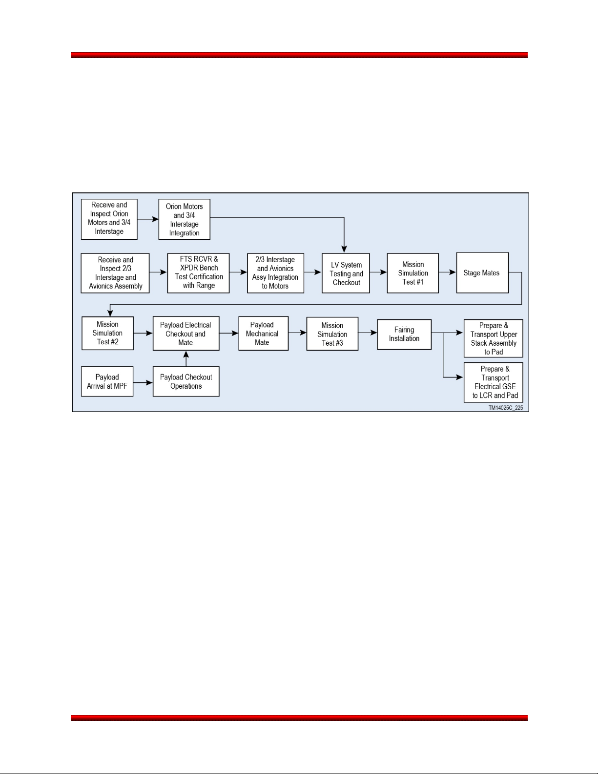
Minotaur I User’s Guide Section 7.0 – Ground and Launch Operations
7.1. Launch Vehicle Integration Overview
Orbital utilizes the same fundamental integration and process flow for all launch vehicles in the Minotaur
family. A flow chart of the launch vehicle integration at the MPF is shown in Figure 7.1-1 for a VAFB
Minotaur I launch. This minimizes the handling complexity for both vehicle and payload. Horizontal
integration of the Minotaur I vehicle upper stages simplifies integration procedures, increases safety and
provides excellent access for the integration team. In addition, simple mechanical and electrical interfaces
reduce vehicle/payload integration times, increase system reliability and minimize vehicle demands on
payload availability.
Figure 7.1-1. Launch Vehicle Processing Flow
7.1.1. Planning and Documentation
Minotaur integration and test activities are controlled by a comprehensive set of Work Packages (WPs)
that describe and document every aspect of integrating and testing the Minotaur launch vehicle and its
payload. All testing and integration activities are scheduled by work package number on an activity
schedule that is updated and distributed daily during field operations. This schedule is maintained by
Orbital and serves as the master document communicating all activities planned at the field site. The
schedule contains notations regarding the status of the work package document and hardware required
to begin the operation. Mission-specific work packages are created for mission-unique or payload-specific
procedures. Any discrepancies encountered are recorded on a Non-Conformance Report and
dispositioned as required. All activities are in accordance with Orbital’s ISO 9001 certification.
7.1.2. Upper Stack Assembly Integration and Test Activities
The upper stack assembly will undergo system level testing at Orbital’s Chandler facility prior to being
shipped to the field. The major vehicle components and subassemblies that comprise the Minotaur I
Upper Stack Assembly, including the Stage 3 and Stage 4 Orion motors, are delivered to Orbital’s MPF
located at VAFB, CA. There, the vehicle is horizontally integrated prior to the arrival of the payload.
Integration is performed at a convenient working height, which allows easy access for component
installation, inspection and test. The integration and test process ensures that all vehicle components and
subsystems are thoroughly tested.
Release 3.0 March 2014 56
Page 70
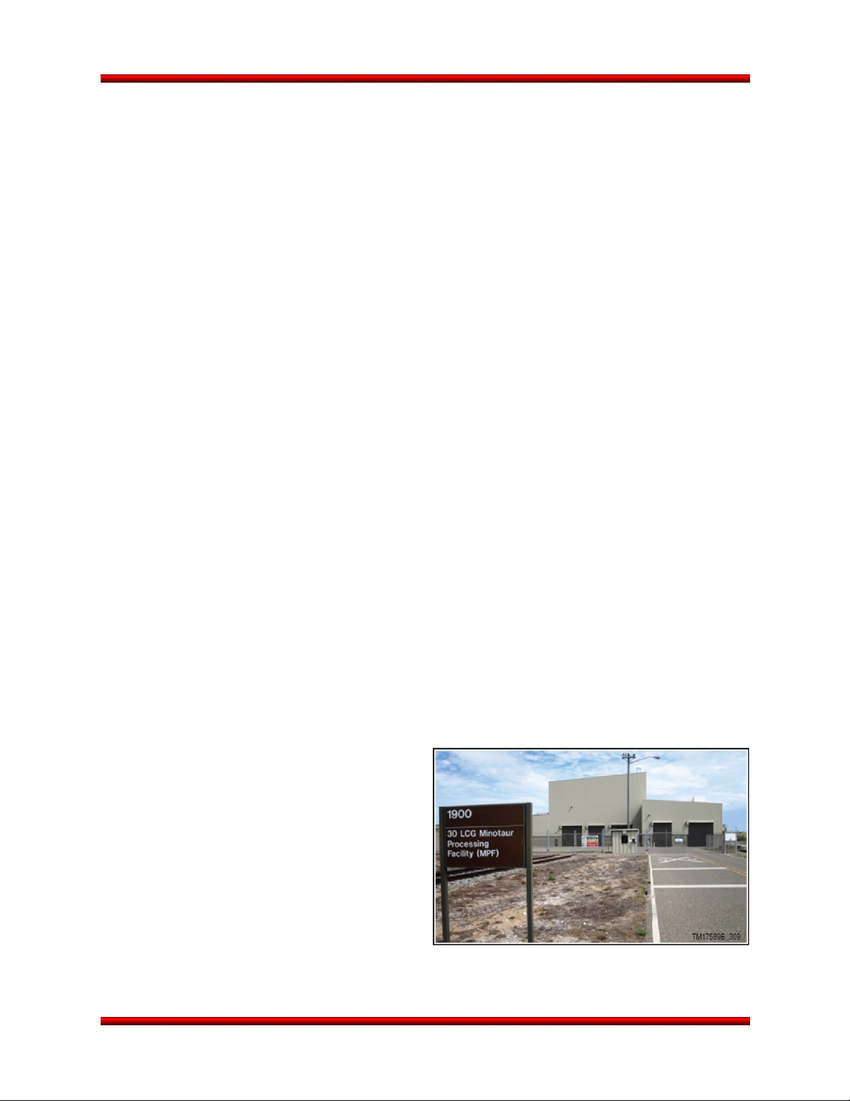
Minotaur I User’s Guide Section 7.0 – Ground and Launch Operations
7.1.3. Minuteman Motor Integration and Test Activities
The Minuteman Stage 1 and 2 motors are refurbished at Hill Air Force Base. They also undergo ordnance
and raceway installation before being shipped directly to the launch pad for emplacement.
7.1.4. Mission Simulation Tests
Orbital will run three Mission Simulation Tests (MST) to verify the functionality of launch vehicle hardware
and software (i.e., MST #1, MST #2, and MST #3). The Mission Simulation Tests use the actual flight
software and simulate a “fly to orbit” scenario using simulated Inertial Navigation System (INS) data. This
allows the test to proceed throughout all mission phases and capture vehicle performance data. The data
will be compared to previous MSTs performed in the factory using the same flight software and hardware.
Since the Minuteman motors are not available at the MPF, a high fidelity simulator consisting of actual
Minuteman components is used. These components provide a realistic assessment of booster
performance during the testing operations. After a thorough data review of all telemetry parameters, the
test configuration is disassembled and prepared for payload integration.
The Mission Simulation is repeated after each major change in vehicle configuration (i.e., Mission
Simulation #2 after stage mate and Mission Simulation #3 after the payload is mechanically integrated).
After each test, a complete review of the data is undertaken prior to proceeding. The payload nominally
participates in Mission Simulation #3.
7.1.5. Launch Vehicle Processing Facilities
The Minotaur Processing Facility (MPF), Building 1900, at VAFB is a 48,000 sq. ft facility used primarily
for LV processing prior to transporting the LV to the appropriate launch site or range for that mission. For
missions out of VAFB, the MPF has adequate floor space and infrastructure to support concurrent launch
vehicle and payload processing. An exterior view of the MPF is shown in Figure 7.1.5-1. Should the MPF
be utilized for payload processing, it is expected that the payload and Minotaur launch vehicle would be
processed in separate sections of the High Bay area.
The MPF has infrastructure capability to support payload processing requirements in terms of security,
electrical and communications service, overhead crane, and a temperature and humidity controlled
environment. High Cleanliness operations are discussed further in Section 8.2.3.1 as required per the
mission and particle containment requirements.
7.2. Payload Processing/Integration
Payloads typically undergo initial checkout and
preparation for launch at a Payload Processing
Facility, which can be either a government
provided or commercial facility. The payload is
then sent to the MPF for integration with the
Minotaur I upper stack. After arrival at the MPF, the
payload completes its own independent verification
and checkout prior to beginning the integration
process with Minotaur I. Following completion of
Minotaur I and payload testing, the payload will be
enclosed inside the fairing. The required payload
environments are then maintained inside the
fairing until launch.
Figure 7.1.5-1. Minotaur I Processing Is
Performed at the MPF at VAFB
Release 3.0 March 2014 57
Page 71
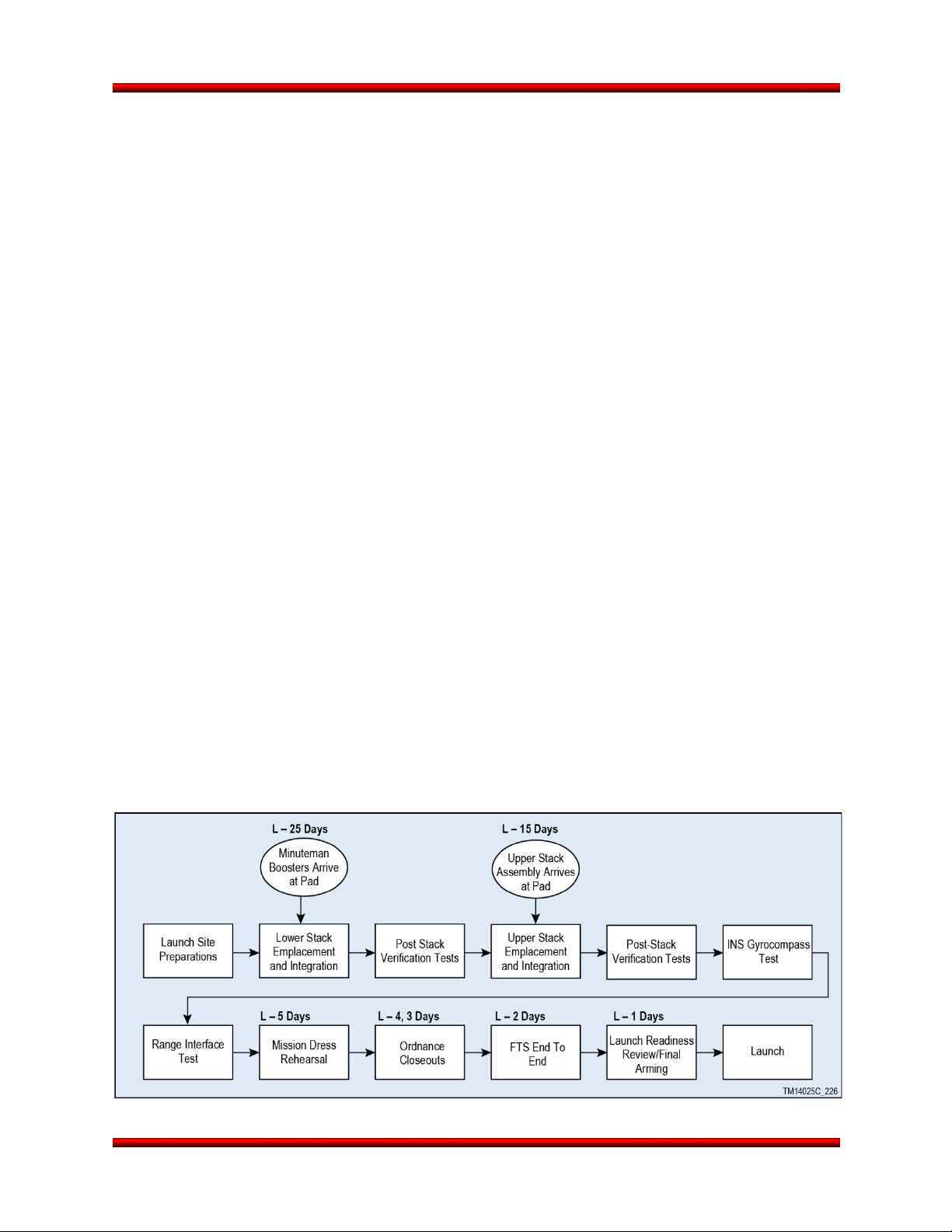
Minotaur I User’s Guide Section 7.0 – Ground and Launch Operations
7.2.1. Payload to Minotaur I Integration
The integrated launch processing activities are designed to simplify final launch processing while
providing a comprehensive verification of the payload interface. The systems integration and test
sequence is engineered to ensure all interfaces are verified.
7.2.2. Pre-Mate Interface Testing
If required, the electrical interface between Minotaur I and the payload is verified using a mission unique
Interface Verification Test (IVT) to jointly verify that the proper function of the electrical connections and
commands. These tests, customized for each mission, typically check bonding, electrical compatibility,
communications, discrete commands and any off nominal modes of the payload. For pre-mate verification
of the mechanical interface, the separation system can also be made available before final payload
preparations.
7.2.3. Payload Mating and Verification
Once the payload aft end closeouts are completed, the payload will be both mechanically and electrically
mated to the Minotaur I. Following mate, the flight vehicle is ready for the final integrated systems test,
Mission Simulation #3.
7.2.4. Final Processing and Fairing Closeout
After successful completion of Mission Simulation #3, all consumables are topped off and ordnance is
connected. Similar payload operations may occur at this time. Once consumables are topped off, final
vehicle / payload closeout is performed and the fairing is installed. The payload will coordinate with
Orbital access to the payload from payload mate until final closeout before launch.
7.2.5. Payload Propellant Loading
Payloads utilizing integral propulsion systems with propellants such as hydrazine can be loaded and
secured through coordinated OSP arrangements. This is a non-standard service.
7.3. Launch Operations
At the completion of activities at the MPF and PPF, the final phase of the Launch campaign is entered.
This begins with the stacking of the booster stages and culminates with the launch of the Minotaur I and
payload. A notional launch operations flow chart is shown in Figure 7.3-1. The L-minus dates may vary
from mission to mission depending on vehicle configuration and other range commitments. Launch
operations activities are described in more detail in the subsections to follow.
Figure 7.3-1. Minotaur I Launch Site Operations
Release 3.0 March 2014 58
Page 72
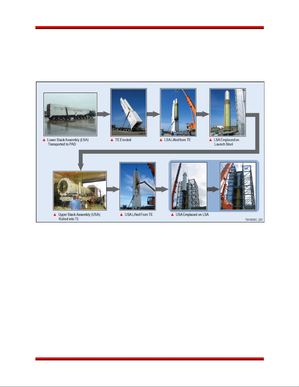
Minotaur I User’s Guide Section 7.0 – Ground and Launch Operations
7.3.1. Booster Assembly Stacking/Launch Site Preparation
Prior to the arrival of the Minuteman boosters, the site is prepared for launch operations with the
installation of the launch stand adapter. The Lower Stack Assembly, consisting of the Minuteman motors,
is delivered directly to the launch pad from Hill Air Force Base. Following emplacement, the Upper Stack
Assembly is horizontally transported from the MPF to the pad and emplaced, as shown in Figure 7.3.1-1
as performed at VAFB SLC-8.
Figure 7.3.1-1. Minotaur I Uses Vertical Integration for Each Booster Stage, the Guidance Control
Assembly, and the Encapsulated Payload Assembly
7.3.2. Final Vehicle Integration and Test
After the vehicle is fully stacked at the pad, final tests are completed to verify vehicle integrity and all
interfaces to the range are exercised. A range interface test is performed to verify all the RF systems, and
an end-to-end FTS test is performed to certify the FTS system. The ACS and separation systems are
pressurized to final flight pressure, and final vehicle preparations are accomplished. The vehicle and
launch team are then ready for the final countdown and launch.
7.3.3. Launch Vehicle Arming
Following final vehicle testing, the launch vehicle is armed and the pad is cleared for launch. The majority
of these arming activities occurs at L-1 day and brings the Minotaur launch vehicle nearly to its launch
day configuration. L-1 day is also typically the last opportunity for payload access. The remaining arming
steps (final arming) take place mid-way during the countdown on launch day.
Release 3.0 March 2014 59
Page 73

Minotaur I User’s Guide Section 7.0 – Ground and Launch Operations
Countdown Timeline
7.3.4. Launch
The typical Minotaur final countdown procedure commences at 5 hours prior to the required launch time.
Figure 7.3.4-1 describes the nominal Minotaur I launch day flow. These activities methodically transition
the vehicle from a safe state to that of launch readiness. Payload tasks, as necessary, are included in the
countdown procedure and are coordinated by the Minotaur I Launch Conductor. The Minotaur I is shown
ready for launch in Figure 7.3.4-2.
Figure 7.3.4-1. Notional Minotaur
Figure 7.3.4-2. Minotaur I Prepared for Launch
7.3.5. Launch Control Organization
The Launch Control Organization is split into two groups: the Management group and the Technical
group. The Management group consists of senior range personnel and Mission Directors/Managers for
the launch vehicle and payload who provide authority to proceed at selected points in the countdown. The
Technical Group consists of the Launch Vehicle, Payload and Range personnel responsible for execution
of the launch operation, to include data review and launch readiness assessment. The Payload’s
members of the technical group are engineers who provide technical representation in the control center.
The Launch Vehicle’s members of the technical group are engineers who prepare the Minotaur for flight,
review and assess data that is displayed in the Launch Control Room (LCR) and provide technical
representation in the LCR and in the Launch Operations Control Center (LOCC). The Range’s members
of the technical group are personnel that maintain and monitor the voice and data equipment, tracking
facilities and all assets involved with RF communications with the launch vehicle. In addition, the Range
provides personnel responsible for the Flight Termination System monitoring and commanding.
Release 3.0 March 2014 60
Page 74

Minotaur I User’s Guide Section 7.0 – Ground and Launch Operations
7.3.6. Launch Rehearsals
Two rehearsals are conducted prior to each launch. The first is conducted at approximately L-10 days
and is used to acquaint the launch team with the communications systems, reporting, problem solving,
launch procedures and constraints, and the decision making process. The first rehearsal is
communications only (i.e., the Minotaur launch vehicle and payload are not powered on and range assets
are not active). It is typically a full day in duration and consists of a number of countdowns performed
using abbreviated timelines, clock jumps, and off-nominal situations. All aspects of the team’s
performance are exercised, as well as hold, scrub, and recycle procedures. The operations are critiqued
and the lessons learned are incorporated prior to the Mission Dress Rehearsal (MDR) at L-5 days
(typical). The MDR is the final rehearsal prior to the actual launch day operation. It will ensure that
problems encountered during the first rehearsal have been resolved. The MDR exercises the entire 5
hour Minotaur I countdown procedure and simulated post launch events. The Launch Vehicle is powered
for this rehearsal and range assets perform operations as they would on launch day. There are no
planned off-nominal events; however, the team will react to real world anomalies as they would on launch
day. MDR ends with successful completion of the countdown procedure.
All Customer personnel involved with launch day activities participate in both rehearsals.
Release 3.0 March 2014 61
Page 75
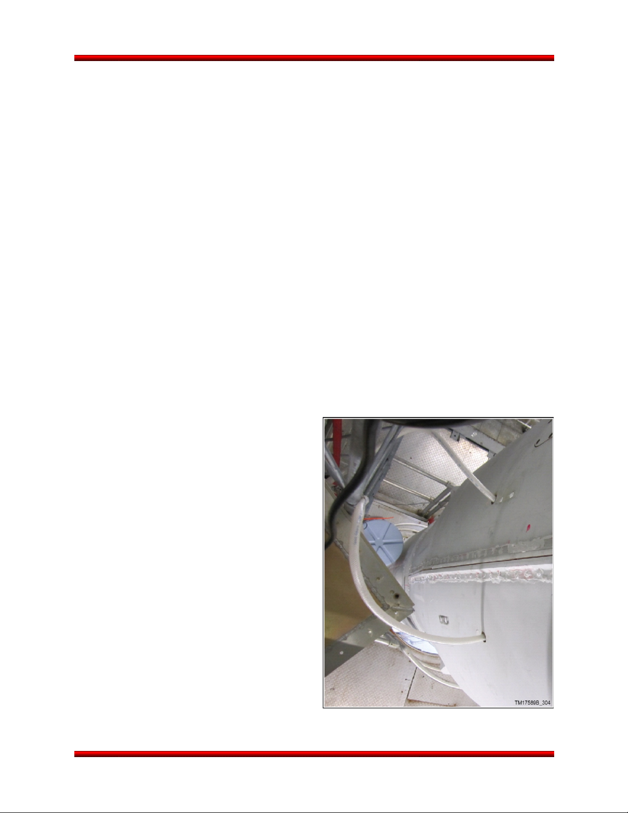
Minotaur I User’s Guide Section 8.0 – Optional Enhanced Capabilities
Fairing (Flyaway at Liftoff)
8. OPTIONAL ENHANCED CAPABILITIES
The Minotaur launch service is structured to provide a baseline vehicle configuration which is then
augmented with optional enhancements to meet the unique needs of individual payloads. The baseline
vehicle capabilities are defined in the previous sections and the optional enhanced capabilities are
defined below. The enhanced options allow customization of launch support and accommodations to the
Minotaur I designs on an efficient, “as needed” basis.
8.1. Separation System
Several different types of optional separation systems and mechanical interfaces are available through
Orbital. Further details can be found in Sections 5.2.4 and 5.2.5.
8.2. Conditioned Air
Conditioned air is included in the baseline vehicle cost and was described previously in Section 4.6.1.
The Nitrogen Purge and Enhanced Contamination Control enhancements complement this capability as
described in the Sections 8.3 and 8.6. For Minotaur I, conditioned air is not provided during transport or
lifting operations.
8.3. Nitrogen Purge
Clean, dry gaseous nitrogen (GN
can be provided to the payload in a Class 10,000 environment for continuous purge of the payload after
fairing encapsulation until final payload closeouts (non-fly away) or lift-off (flyaway configuration shown in
Figure 8.3-1). This enhancement uses a flow regulated nitrogen ground supply connected to the fairing.
The nitrogen flow control regulator ensures the purge is supplied at a minimum flow rate of 5 standard
cubic feet per minute with a capability of up to 8 standard cubic feet per minute. A manifold mounted to
the inside of the fairing wall feeds lines up the
fairing wall to purge points of interest on the
payload. Purge nozzles can be positioned on the
fairing wall and pointed at the payload instrument.
Alternatively, a fly away configuration can be used
where the purge line connects to a manifold on the
payload and is pulled free during fairing separation.
This continuous purge can be supplied from
payload encapsulation through launch, including
during transport to the pad, as demonstrated on
past Minotaur I missions.
8.4. Additional Access Panel
As already discussed in Section 5.1.3, additional
doors of the same size and configuration as the
standard single access door can be provided. The
location of the fairing access door is documented
within the mission-specific ICD. Figure 8.4-1 shows
multiple access panels used on the Minotaur I
ORS-1 mission as located on the optional Minotaur
61” fairing. Figures 5.1.3-1 and 5.1.3-2 define the
allowable access door envelopes. Typical missions
have included two access doors, at various
) purge meeting Grade B specifications as defined in MIL-P-27401C
2
Figure 8.3-1. GN2 Purge Interface To Minotaur
Release 3.0 March 2014 62
Page 76

Minotaur I User’s Guide Section 8.0 – Optional Enhanced Capabilities
Figure 8.4-1. Multiple Access Doors Were Demonstrated on the Optional Minotaur I Large Fairing
locations on the fairing. Required door locations outside the allowable envelope are evaluated on a
mission-specific basis. Other fairing access configurations, such as small circular access panels, can be
provided as non-standard, mission-specific enhancements. Additional mission-specific effort can be
minimized if a previously flown access door configuration is chosen.
8.5. Enhanced Telemetry
Enhanced telemetry provides for mission specific instrumentation and telemetry components to support
additional payload, LV, or experiment data acquisition requirements. This enhancement provides a
dedicated telemetry link with a baseline data rate of 2 Mbps. Additional instrumentation or signals such as
strain gauges, temperature sensors, accelerometers, analog and digital data can be configured to meet
mission specific requirements. This capability was successfully demonstrated on the first five Minotaur IV
launches. Non-recurring efforts are required to offer enhanced telemetry on Minotaur I. These efforts
include modifications to the vehicle telemetry encoder, cabling, and software. Typical enhanced telemetry
instrumentation includes accelerometers and microphones intended to capture high frequency transients
such as shock and random vibration.
Release 3.0 March 2014 63
Page 77

Minotaur I User’s Guide Section 8.0 – Optional Enhanced Capabilities
8.6. Enhanced Contamination Control
To meet the requirement for a low contamination
environment, Orbital uses existing processes
developed and demonstrated on the Minotaur and
Pegasus programs. These processes are designed
to minimize out-gassing, supply a Class 10,000
clean room environment, assure a high cleanliness
payload envelope, and provide a HEPA-filtered,
controlled humidity environment after fairing
encapsulation. Orbital leverages extensive payload
processing experience to provide flexible,
responsive solutions to mission-specific payload
requirements (Figure 8.6-1).
8.6.1. Low Outgassing Materials
Orbital’s existing high cleanliness design and
integration processes ensure that all materials
used within the encapsulated volume have
outgassing characteristics of less than 1.0% Total
Mass Loss (TML) and less than 0.1% Collected
Volatile Condensable Mass (CVCM) in accordance
with ASTM E59. If materials within the
encapsulated volume cannot meet low outgassing
characteristics because of unique mission
requirements, a contamination control plan is
developed to ensure controls are in place to
eliminate any significant effect on the payload.
8.6.2. High Cleanliness Integration Environment
With the enhanced contamination control option, the encapsulated payload element of the vehicle is
processed in an ISO Standard 14644-1 Class 10,000 environment during all payload processing activities
up to fairing encapsulation (ISO 7). The PPF clean room utilizes HEPA filtration units to filter the air and
ensure hydrocarbon content is maintained at ≤15 ppm, with humidity maintained at 30-60% relative
humidity. Depending on payload requirements, the clean room can also be certified as Class 100,000
(ISO 8) while still providing tighter environmental control than the standard high-bay environment, thereby
streamlining access and payload processing.
8.6.3. HEPA-Filtered Fairing Air Supply
With the enhanced contamination control option, the ECU continuously purges the fairing volume with
clean filtered air while maintaining temperature, humidity, and cleanliness. Orbital’s ECU incorporates a
HEPA filtration unit along with a hydrocarbon filter adaptor to provide Class 10,000 (ISO 7) air and ensure
hydrocarbon content is maintained at ≤15 ppm, with humidity maintained as stated in section 4.6.1.
Orbital monitors the supply air for particulate matter via a probe installed upstream of the fairing inlet duct
prior to connecting the air source to the payload fairing.
Figure 8.6-1. Minotaur Team Has Extensive
Experience in a Payload Processing Clean
Room Environment
Release 3.0 March 2014 64
Page 78

Minotaur I User’s Guide Section 8.0 – Optional Enhanced Capabilities
8.6.4. Fairing Surface Cleanliness
The inner surface of the fairing and exposed launch vehicle assemblies are cleaned to Visibly Clean Plus
Ultraviolet cleanliness criteria which ensures no particulate matter visible with normal vision when
inspected from 6 to 18 inches under 100 foot candle incident light, as well as when the surface is
illuminated by black light at 3200 to 3800 Angstroms. Process and procedures for inspection and the
bagging of material to preclude contamination during shipment to the field are in place.
8.7. Secure FTS
The Secure FTS (Figure 8.7-1) is achieved with the L-3 Cincinnati Electronics Model CRD-120/205
Launch Vehicle Command Receiver/Decoder that is compatible with the "High-Alphabet" range safety
modulation format. The receiver uses a pre-stored code unique to each specific vehicle to issue
configuration and termination commands. This provides an increased level of security over the standard
FTS systems that use a basic 4 tone combination for receiver command and control.
Figure 8.7-1. Orbital’s Secure FTS System Block Diagram
The CRD-120/205 Launch Vehicle Command Receiver/Decoder was designed specifically to operate on
the Delta expendable space launch vehicles for range safety flight termination. This design incorporates
redundancy in both hardware and software and High Reliability piece-parts (in accordance with ELV-JC002D) to ensure reliable, fail-safe operation.
8.8. Over Horizon Telemetry
A Telemetry Data Relay Satellite System (TDRSS) interface can be added as an enhancement to provide
real-time telemetry coverage during blackout periods with ground based telemetry receiving sites. TDRSS
was successfully demonstrated on past Minotaur missions. The TDRSS telemetry system enhancement
consists of a LCT2 TDRSS transmitter, an antenna (Figure 8.8-1), an RF switch, and associated ground
test equipment. The RF switch is used during ground testing to allow for a test antenna to be used in lieu
of the flight antennas. Near the time when telemetry coverage is lost by ground based telemetry receiving
Release 3.0 March 2014 65
Page 79

Minotaur I User’s Guide Section 8.0 – Optional Enhanced Capabilities
sites, the LV switches telemetry output to the
TDRSS antenna and points the antenna towards
a TDRSS satellite. The TDRSS relays the
telemetry to the ground where it is then routed to
the launch control room (Figure 8.8-2). A cavity
backed or phased array antenna can be used
depending on data rate requirements. The
TDRSS system proposed includes the launch
vehicle design, analysis, hardware and launch
vehicle testing. For this option, arrangements
need to be made with NASA for system support
and planning, management, scheduling, satellite
usage, ground operations, and data processing.
8.9. Increased Insertion Accuracy
Enhanced insertion accuracy can be provided
through the use of a Hydrazine Auxiliary
Propulsion System (HAPS). 6DOF analyses show
the HAPS system provides a controlled impulse
to achieve the accuracies shown in Table 8.9-1
(Insertion is for both apse and non-apse).
The HAPS propulsion system consists of a
centrally mounted tank containing approximately
100 lbm of hydrazine and three fixed axial
thrusters. The hydrazine tank contains an integral
propellant management device which supports
several zero gravity restarts. The system is
integrated inside of a dedicated HAPS stage
avionics structure that separates from the Stage 4
assembly. After Stage 4 burnout and separation
from the Stage 4 assembly, the HAPS hydrazine
thrusters provide additional velocity for improved
performance and precise orbit insertion. On the
Minotaur I vehicle, the HAPS is integrated into the
Pegasus-developed extended avionics cylinder
which is used in lieu of the standard Minotaur
avionics structure.
8.10. Payload Isolation System
Orbital offers a flight proven payload isolation system as a non-standard service. The Softride for Small
Satellites (SRSS) was developed by Air Force Research Laboratory (AFRL) and CSA Engineering. It has
successfully flown on numerous Minotaur missions. The typical configuration is shown in Figure 8.10-1.
This mechanical isolation system has demonstrated the capability to significantly alleviate the transient
dynamic loads that occur during flight. The isolation system can provide relief to both the overall payload
center of gravity loads and component or subsystem responses. Typically the system will reduce transient
loads to approximately 25% of the level they would be without the system. The exact results will vary for
Figure 8.8-1. TDRSS 20W LCT2 Transmitter and
Cavity Backed S-band Antenna
Figure 8.8-2. TDRSS Notional Telemetry Flow
Table 8.9-1. Enhanced Insertion Accuracies
Error Type Tolerance
Insertion
Inclination
<18.5 km (10 nmi) (3-σ)
<0.05° (3-σ)
Release 3.0 March 2014 66
Page 80

Minotaur I User’s Guide Section 8.0 – Optional Enhanced Capabilities
each particular spacecraft and with location on the
spacecraft. Generally, a beneficial reduction in
shock and vibration will also be provided. The
isolation system does impact overall vehicle
performance by approximately 9 to 18 kg (20 to 40
lb) and the available payload dynamic envelope by
up to 5.08 cm (2.0”) axially and up to 2.54 cm
(1.0”) laterally.
8.11. Orbital Debris Mitigation
For each mission, Orbital evaluates the orbit
lifetime of all stages and hardware that reach Earth
orbit. In the event that Minotaur hardware is left in
an orbit that lasts for 25 years or longer, this
enhancement is required to properly dispose and
mitigate causality expectations of the hardware in
accordance with AFI 91-217. Figure 8.11-1 shows
the altitudes where Low Earth Orbits last for more
than 25 years. For this enhancement, Orbital
optimizes the orbital debris mitigation system to the
specific mission requirements. For example, in
some cases it might be more efficient to raise the
final stage to an orbit in the LEO Disposal region.
In other cases it would be best to lower the final
stage to an orbit where natural forces can return
the hardware to the Earth’s atmosphere within 25
years. In some cases, deployment of a solar sail or
tether may be required. Orbital will determine the
optimal solution on a mission-specific basis.
8.12. Dual and Multi Payload Adapter Fittings
Detailed in Section 5.2.4.2.
Figure 8.10-1. Minotaur I SRSS Significantly
Attenuates Peak LV Dynamic Environments
Figure 8.11-1. Operational and Disposal LEOs
Release 3.0 March 2014 67
Page 81
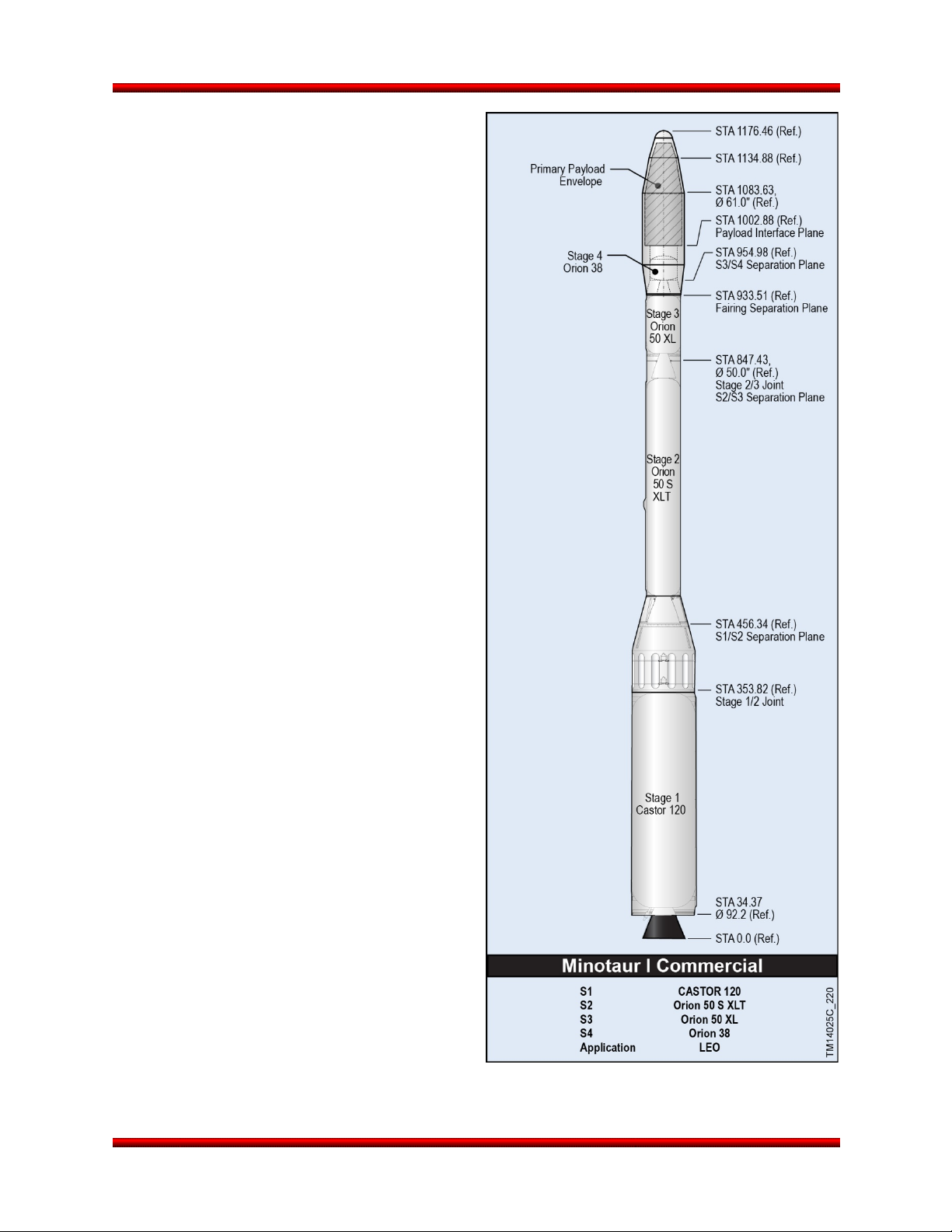
Minotaur I User’s Guide Section 8.0 – Optional Enhanced Capabilities
8.13. Minotaur I Launch Vehicle Enhanced Performance Configuration
8.13.1. Minotaur I Commercial
The Minotaur I Commercial space launch vehicle
represents a substantial (over 25%) increase in
performance with minimal vehicle changes, shown
in Figure 8.13.1-1. The configuration was
established for payloads that do not have
government sponsorship but require the highly
reliable Minotaur I capability. The Minotaur I
Commercial vehicle utilizes the identical flight
proven third and fourth stages, mechanical
structures, avionics, pneumatics, and ordnance
subsystems as the base Minotaur I vehicle. The
Minotaur I Commercial vehicle replaces the GFE
Stage 1 and Stage 2 boosters with commercially
available Castor 120 and Orion 50S XLT boosters,
respectively. The S1/2 interstage is flight proven
and is vented to minimize vehicle loads during the
hot separation event by jettisoning vent panels just
prior to Stage 2 ignition. This vehicle configuration
can place a 1050 kg payload into a 740 km by 740
km sun-synchronous orbit when launched from
VAFB and 390 kg to GTO from CCAFS.
8.14. Large Fairing
Details are in Section 5.1.2.
8.15. Hydrazine Servicing
Under this enhancement, Orbital provides
hydrazine fueling service for the SV though a
contract to United Paradyne Corporation (UPC).
Previous 30SW rules placed restrictions on UPC’s
ability to use GFE equipment to provide hydrazine
servicing to non-Government entities. This led
UPC to develop and manufacture their own GSE
and they now possess the ability to contract
directly with Orbital. A typical propellant loading
schematic is shown in Figure 8.15-1.
Figure 8.13.1-1. Minotaur I Commercial Offers
Exceptional Performance with Proven Reliability
Release 3.0 March 2014 68
Page 82

Minotaur I User’s Guide Section 8.0 – Optional Enhanced Capabilities
Figure 8.15-1. Typical Propellant Loading Schematic
The scope of this enhancement includes the procurement of hydrazine fuel, the preparation of
documentation for fueling operations, the support of safety and integrated operations meetings, the
provision of equipment needed for SCAPE operation, including personal protection equipment (if
necessary) and fuel transfer cart, and all personnel required to conduct fuel loading operations.
Emergency unloading operations can also be supported if desired. Figure 8.15-2 shows hardware used
by UPC for hydrazine servicing. The recurring price includes costs for de-fueling operations that would
not be required in nominal launch processing.
Release 3.0 March 2014 69
Page 83
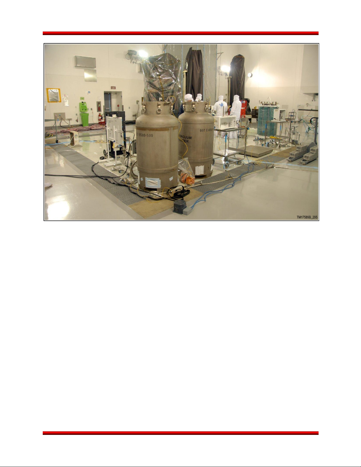
Minotaur I User’s Guide Section 8.0 – Optional Enhanced Capabilities
Figure 8.15-2. UPC Provides Reliable and Demonstrated Hydrazine Servicing for Minotaur
8.16. Nitrogen Tetroxide Service
Under this enhancement, Orbital provides Nitrogen Tetroxide (NTO) loading service for the SV though a
contract to UPC. The scope of this enhancement includes the procurement of NTO, the preparation of
documentation for loading operations, the support of safety and integrated operations meetings, the
provision of equipment needed for SCAPE operation, including personal protection equipment (if
necessary) and NTO transfer cart, and all personnel required to conduct fuel loading operations.
Emergency unloading operations can also be supported if desired.
Release 3.0 March 2014 70
Page 84

Minotaur I User’s Guide Section 8.0 – Optional Enhanced Capabilities
Figure 8.18-1. Minotaur I Lite Ballistic Performance
8.17. Poly-Pico Orbital Deployer (P-POD)
When there is excess performance available on a Minotaur mission, there is an opportunity to fly one or
more P-PODS. Small CubeSats deployed from customer provided P-PODs were successfully flown on
multiple Minotaur missions. A single P-POD can deploy up to 3 CubeSats.
The P-PODs are mounted on shock isolated plates located on the Orion 38 motor case (Figure 8.17-1)
and are deployed in the aft direction following Stage 4 burnout. A standard pyro pulse from the launch
vehicle is used to deploy the P-PODs. The Minotaur I launch vehicle is capable of deploying up to two PPODs per mission, assuming the use of the Large Fairing (61”) Enhancement. Due to their mounting
location, P-PODs can be easily integrated to the launch vehicle on a fully non-interference basis from the
primary spacecraft, thus minimizing impacts to the primary mission spacecraft integration operations. This
enhancement assumes the P-PODs are added to the manifest early enough in the contract that extensive
rework is not required.
Figure 8.17-1. P-PODs Have Successfully Flown On Multiple Minotaur Missions
8.18. Suborbital Performance
The flight proven Minotaur I provides the basis
for an enhanced configuration, Minotaur I Lite,
to meet various suborbital mission demands.
Minotaur I Lite maintains the existing Minotaur I
vehicle systems and simply removes the 4th
stage to provide a reliable, proven, and robustly
performing suborbital vehicle (see Figure 8.18-1
for performance). In addition to providing
significant downrange performance, Orbital
draws from many existing, proven, successful
guidance schemes to meet the unique targeting
needs of the suborbital customer including the
highly accurate Pierce Point algorithm proven
on Minotaur II and Minotaur IV.
Under the Suborbital Performance Modification for Minotaur I, the Orion 38 4th stage solid rocket motor
and associated components are removed from the Minotaur I orbital configuration (Figure 8.18-2).
Release 3.0 March 2014 71
Page 85

Minotaur I User’s Guide Section 8.0 – Optional Enhanced Capabilities
Minotaur I Lite provides a larger volume and greater stack height to the suborbital payload. For
clearances to fairing deployment components and to maintain proven fairing deployment dynamics, a
simple aluminum adapter cylinder is used between the 3/4 interstage and the avionics section. The
adapter cylinder is the only new structure; the electrical and ordnance designs above and below remain
unchanged from the standard Minotaur I. Payload and launch vehicle environments remain enveloped by
previously established and well defined Minotaur I levels. Minotaur I Lite maintains the same high level of
payload access, power, discrete, and communication interfaces as the standard Minotaur I LV. Relatively
minor design, model, analysis, and procedure updates ensure Minotaur I Lite maintains the high
standards of the Minotaur family of vehicles.
Figure 8.18-2. Minotaur I-Lite Replaces the Orion 38 with a Low Cost and Risk Simple Aluminum
Cylinder
Release 3.0 March 2014 72
Page 86
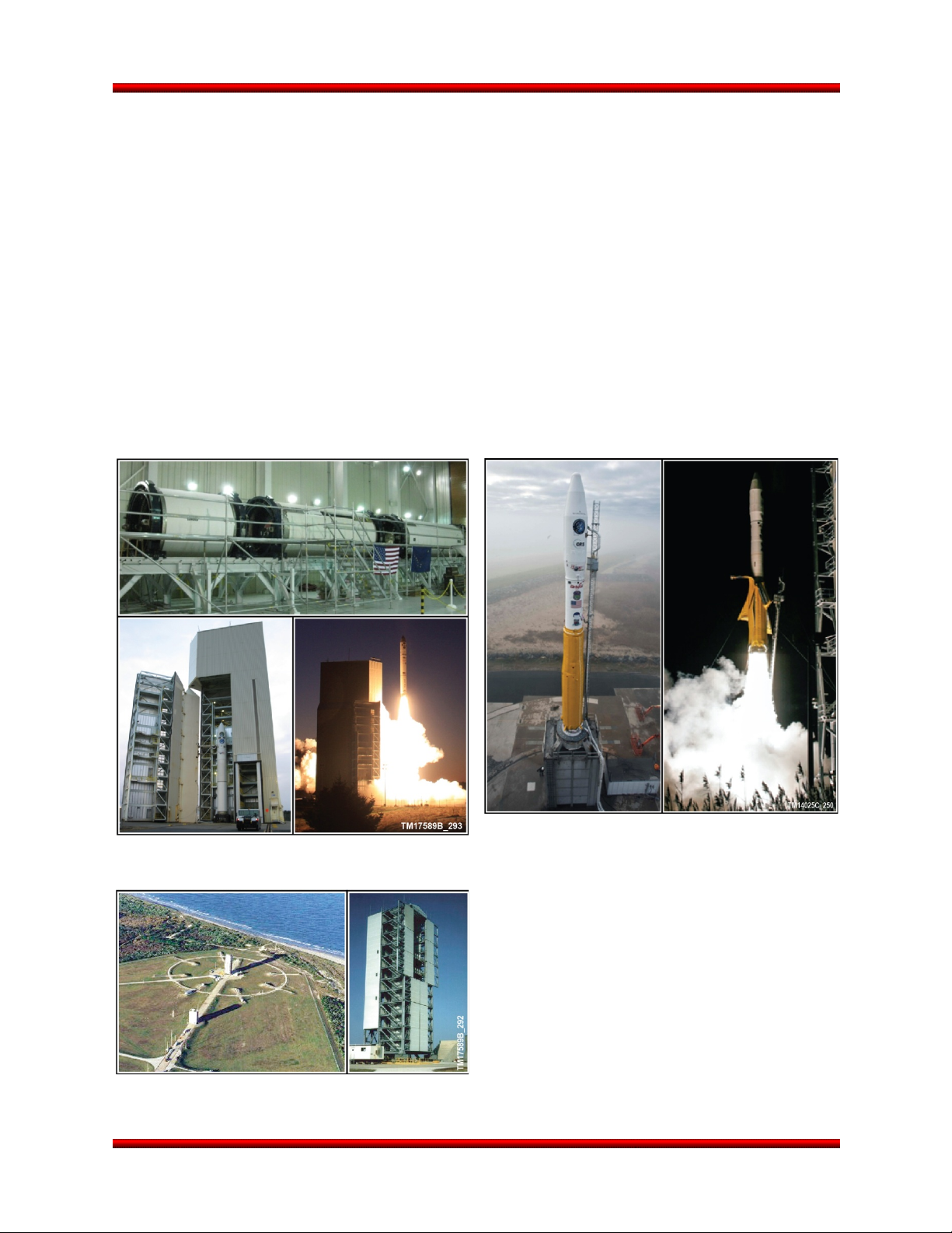
Minotaur I User’s Guide Section 8.0 – Optional Enhanced Capabilities
Supports All Minotaur Configurations
8.19. Alternate Launch Location
Orbital has extensive experience processing and launching out of multiple Government and commercial
launch sites. Minotaur systems are designed to accommodate missions from multiple ranges with minimal
dedicated infrastructure. The Minotaur flight safety systems and Range interface requirements are well
documented and approved by multiple safety organizations. Orbital has experience working closely with
various ranges to address the ground and flight safety requirements to ensure a safe and successful
launch.
While VAFB is home to the Minotaur Processing Facility, the Minotaur system was designed from the
beginning to launch from all four of the existing commercial spaceports: Spaceport Systems
International’s SLC-8 at VAFB, AADC’s Kodiak Launch Complex in Alaska (Figure 8.19-1), Space
Florida’s LC-46 at CCAFS (Figure 8.19-2), and Mid-Atlantic Regional Spaceport’s Pad 0B at Wallops
Island, Virginia (Figure 8.19-3). Minotaur can also support other ranges and austere sites as a nonstandard service on a case-by-case basis.
Figure 8.19-1. Minotaur IV Vehicles Have
Successfully Launched From KLC
Figure 8.19-2. Launch Complex 46 at CCAFS
Release 3.0 March 2014 73
Figure 8.19-3. Minotaur I Vehicles Have
Successfully Launched Multiple Times From
Wallops
Page 87

Minotaur I User’s Guide Appendix A
APPENDIX A
PAYLOAD QUESTIONNAIRE
Release 3.0 March 2014 A-1
Page 88

Minotaur I User’s Guide Appendix A
SATELLITE IDENTIFICATION
FULL NAME:
ACRONYM:
OWNER/OPERATOR:
INTEGRATOR(s):
SPACE CRAFT AND
MISSION DESCRIPTION
ORBIT INSERTION REQUIREMENTS*
SPHEROID Standard (WGS-84, Re = 6378.137 km)
Other:
ALTITUDE Insertion Apse: Opposite Apse:
nmi
±
or...
INCLINATION
ORIENTATION Argument of Perigee: Longitude of Ascending Node (LAN):
Semi-Major Axis: Eccentricity:
±
± deg
± deg ± deg
Right Ascension of Ascending Node (RAAN):
± deg For Launch Date:
km ±
nmi
km ≤ e ≤
nmi
km
* Note: Mean orbital elements
Release 3.0 March 2014 A-2
Page 89

Minotaur I User’s Guide Appendix A
LAUNCH WINDOW REQUIREMENTS
NOMINAL LAUNCH DATE: LAUNCH SITE:
OTHER CONSTRAINTS (if not already implicit from LAN or RAAN requirements, e.g., solar beta angle,
eclipse time constraints, early on-orbit ops, etc):
Release 3.0 March 2014 A-3
Page 90
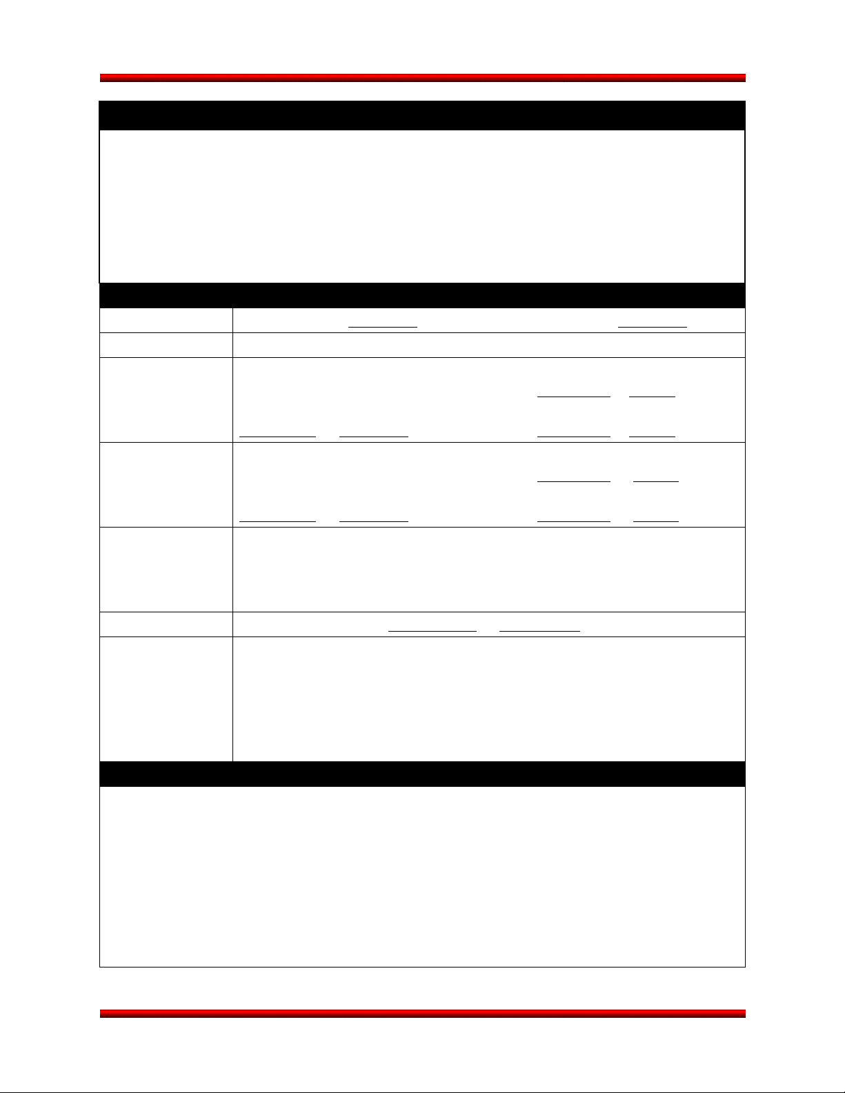
Minotaur I User’s Guide Appendix A
Briefly describe the satellite early on-orbit operations, e.g., event triggers (separation sense, sun
EARLY ON-ORBIT OPERATIONS
acquisition, etc), array deployment(s), spin ups/downs, etc:
SATELLITE SEPARATION REQUIREMENTS
ACCELERATION Longitudinal: ≤ g’s Lateral: ≤ g’s
VELOCITY Relative Separation Velocity Constraints:
ANGULAR RATES
(pre-separation) Longitudinal: Pitch: ± deg/sec
± deg/sec Yaw: ± deg/sec
ANGULAR RATES
(post-separation) Longitudinal: Pitch: ± deg/sec
± deg/sec Yaw: ± deg/sec
ATTITUDE
(at deployment)
SPIN UP Longitudinal Spin Rate: ± deg/sec
OTHER Describe Any Other Separation Requirements:
Describe the Origin and Orientation of the spacecraft reference coordinate system, including its
orientation with respect to the launch vehicle (provide illustration if available):
Describe Pointing Requirements Including Tolerances: (Space Craft X,Y,Z)
SPACECRAFT COORDINATE SYSTEM
Release 3.0 March 2014 A-4
Page 91
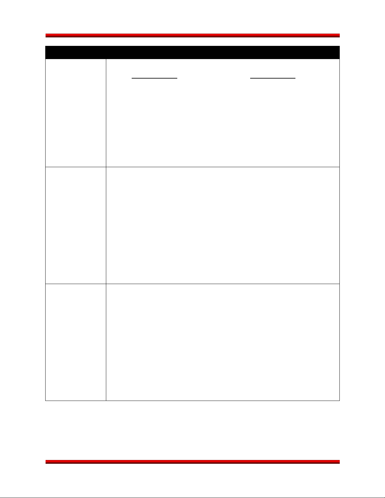
Minotaur I User’s Guide Appendix A
SPACECRAFT PHYSICAL DIMENSIONS
STOWED
CONFIGURATION
Length/Height: Diameter:
in cm in cm
Other Pertinent Dimension(s):
Describe any appendages/antennas/etc which extend beyond the basic satellite
envelope:
ON-ORBIT
CONFIGURATION
If available, provide dimensioned drawings for both stowed and on-orbit configurations.
Release 3.0 March 2014 A-5
Describe size and shape:
Page 92

Minotaur I User’s Guide Appendix A
SPACECRAFT MASS PROPERTIES*
PRE-SEPARATION Inertia units: lbm-in2 kg-m
Mass: lbm kg
Ixx:
Xcg: in cm Iyy:
Izz:
Ycg: in cm Ixy:
Iyz:
Zcg: in cm Ixz:
2
POSTSEPARATION
(non-separating
adapter remaining
with launch vehicle)
Inertia units: lbm-in2 kg-m2
Mass: lbm kg
Ixx:
Xcg: in cm Iyy:
Izz:
Ycg: in cm Ixy:
Iyz:
Zcg: in cm Ixz:
* Stowed configuration, spacecraft coordinate frame
Release 3.0 March 2014 A-6
Page 93

Minotaur I User’s Guide Appendix A
ASCENT TRAJECTORY REQUIREMENTS
SPACECRAFT SLOSH MODEL*
SLOSH MODEL
UNDER 0 g
SLOSH MODEL
UNDER 1 g
Pendulum Mass: lbm kg
Pendulum Length: ft m
Pendulum Xs: in cm
Attachment Ys: in cm
Point Zs: in cm
Natural Frequency of Fundamental Sloshing Mode (Hz): ,
Pendulum Mass: lbm kg
Pendulum Length: ft m
Pendulum Xs: in cm
Attachment Ys: in cm
Point Zs: in cm
Natural Frequency of Fundamental Sloshing Mode (Hz): ,
Free Molecular Heating at Fairing Separation:
(Standard Service: = 360 Btu/ft2/hr)
Fairing Internal Wall Temperature
(Standard Service: = 200°F)
Dynamic Pressure at Fairing Separation:
(Standard Service: = 0.01 lbf /ft2)
Ambient Pressure at Fairing Separation:
(Standard Service: = 0.3 psia)
Maximum Pressure Decay During Ascent:
(Standard Service: = 0.6 psia)
Thermal Maneuvers During Coast Periods:
(Standard Service: none)
Release 3.0 March 2014 A-7
Btu/ft2/hr
FMH ≤ W/m2
deg F
T ≤ deg C
lbf /ft2
q ≤ N/m2
lbf /in2
P ≤ N/m2
lbf /in2/sec
Δ P ≤ N/m2/sec
Page 94
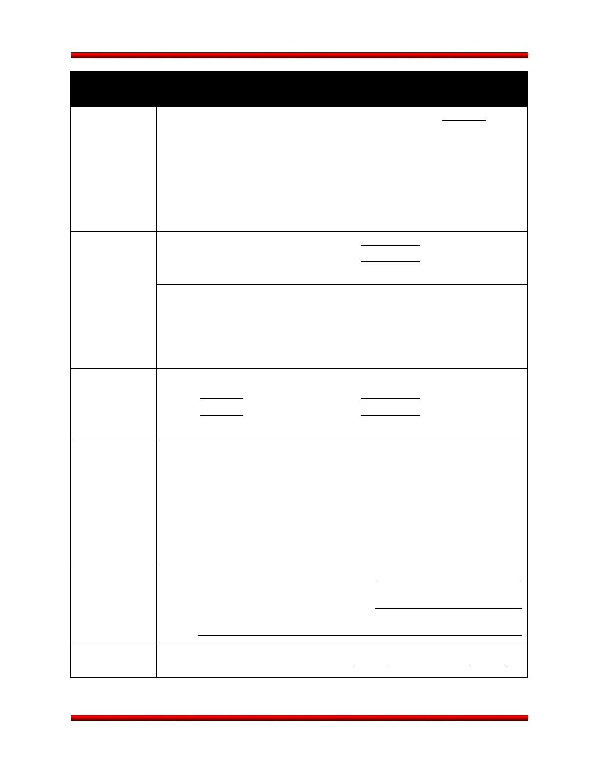
Minotaur I User’s Guide Appendix A
Specify Any Nitrogen Purge Requirements, Including Component Description,
SPACECRAFT ENVIRONMENTS
THERMAL
DISSIPATION
TEMPERATURE Temperature Limits During Max deg F deg C
HUMIDITY Relative Humidity: or, Dew Point:
Spacecraft Thermal Dissipation, Pre-Launch Encapsulated: Watts
Approximate Location of Heat Source:
Thermal Control Provisions: (Paint, Tape, etc.):
Ground/Launch Operations: Min deg F deg C
(Standard Service is 55°F to 80°F)
Component(s) Driving Temperature Constraint:
Approximate Location(s):
Max % Max deg F deg C
Min % Min deg F deg C
(Standard Service is 37 deg F)
NITROGEN
PURGE
CLEANLINESS Volumetric Requirements (e.g. Class 100,000):
LOAD LIMITS Ground Transportation Load Limits Axial ≤ g’s Lateral ≤ g’s
Release 3.0 March 2014 A-8
Location, and Required Flow Rate:
(Nitrogen Purge is a Non-Standard Service)
Surface Cleanliness (e.g. Visually Clean):
Other:
Page 95
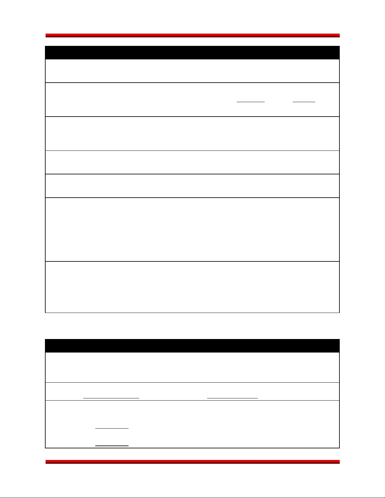
Minotaur I User’s Guide Appendix A
ELECTRICAL INTERFACE
Bonding Requirements:
Are Launch Vehicle Supplied
Pyro Commands Required? Yes / No If Yes, magnitude: amps for msec
(Standard Service is 10 amps for 100 msec)
Are Launch Vehicles Supplied? Yes / No If Yes, describe:
Discrete Commands Required? Yes / No
Is Electrical Access to the Satellite Required... After Encapsulation? Yes / No
at Launch Site Yes / No
Is Satellite Battery Charging Required... After Encapsulation? Yes / No
at Launch Site? Yes / No
Is a Telemetry Interface with the Launch Vehicle Flight Computer Required? Yes / No
If Yes, describe:
Other Electrical Requirements:
Please complete attached sheet of required pass-through signals.
RF RADIATION
Time After Separation Until RF Devices Are Activated:
(Note: Typically, no spacecraft radiation is allowed from encapsulation until 30 minutes after liftoff.)
Frequency: MHz Power: Watts
Location(s) on Satellite (spacecraft coordinate frame):
Longitudinal in cm Clocking (deg), Describe:
Longitudinal in cm Clocking (deg), Describe:
Release 3.0 March 2014 A-9
Page 96

Minotaur I User’s Guide Appendix A
Max
Total Line
1 2 3 4 5 6 7 8 9 10
11
12
13
14
15
16
17
18
19
20
21
22
23
24
25
26
27
REQUIRED PASS-THROUGH SIGNALS
Item
#
Pin Signal Name From LEV To Satellite Shielding
Current
(amps)
Resistance
(ohms)
Release 3.0 March 2014 A-10
Page 97

Minotaur I User’s Guide Appendix A
MECHANICAL INTERFACE
DIAMETER Describe Diameter of Interface (e.g. Bolt Circle, etc):
SEPARATION
SYSTEM
SURFACE
FLATNESS
FAIRING
ACCESS
Will Launch Vehicle Supply the Separation System? Yes / No
If Yes approximate location of electrical connectors:
special thermal finishes (tape, paint, MLI) needed:
If No, provide a brief description of the proposed system:
Flatness Requirements for Sep System or Mating Surface of Launch Vehicle:
Payload Fairing Access Doors (spacecraft coordinate frame):
Longitudinal in cm Clocking (deg), Describe:
Longitudinal in cm Clocking (deg), Describe:
Note: Standard Service is one door
DYNAMICS Spacecraft Natural Frequency:
Axial Hz Lateral Hz
Recommended: > 35 Hz > 12 Hz
OTHER Other Mechanical Interface Requirements:
Release 3.0 March 2014 A-11
Page 98
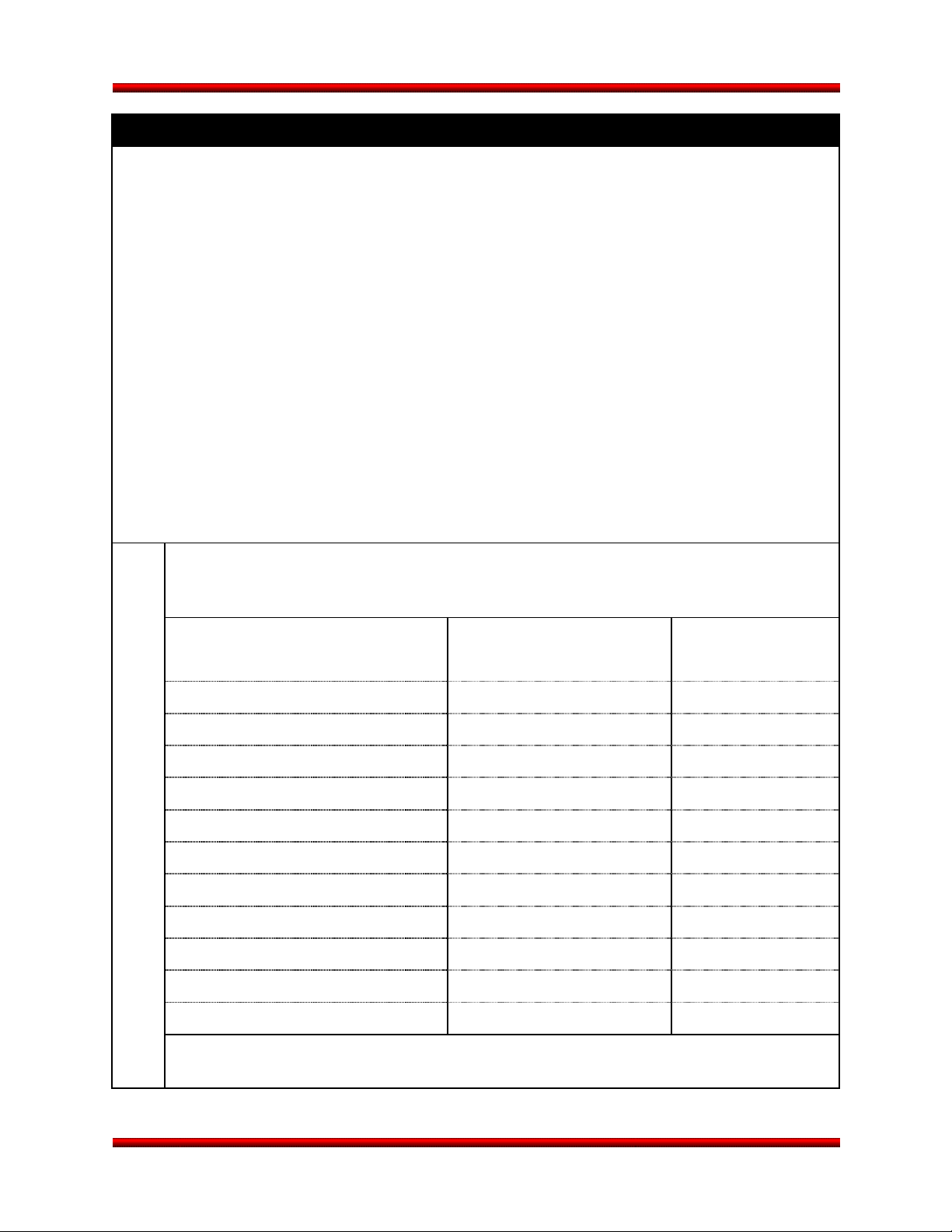
Minotaur I User’s Guide Appendix A
umbilical cable length to spacecraft
GROUND SUPPORT EQUIPMENT
Describe any additional control facilities (other than the baseline Support Equipment Building (SEB) and
Launch Equipment Vault (LEV)) which the satellite intends to use:
SEB Describe (in the table below) Satellite EGSE to be located in the LSV.
[Notes: Space limitations exist in the SEB. 110 m (360 ft)
typical]
Equipment Name / Type Approximate Size (LxWxH) Power Requirements
Is UPS required for equipment in the SEB? Yes / No
Is Phone/Fax connection required in the SEB? Yes / No Circle: Phone / FAX
Release 3.0 March 2014 A-12
Page 99

Minotaur I User’s Guide Appendix A
umbilical cable length to spacecraft
GROUND SUPPORT EQUIPMENT (CONTINUED)
LEV Describe (in the table below) Satellite EGSE to be located in the LEV.
[Notes: Space limitations exist in the LEV. 49 m (160 ft)
typical]
Equipment Name / Type Approximate Size (LxWxH) Power Requirements
Is UPS required for equipment in the LEV? Yes / No
Is Phone/Fax connection required in the LEV? Yes / No Circle: Phone / FAX
Release 3.0 March 2014 A-13
 Loading...