

Orbit OCEANTRX4-500 Installation And Operation Manual
Installation and Operations Manual
Doc P/N: MAN33-0907, Rev. X2
1.15m (45”) Linear Ku-Band
Maritime Stabilized VSAT System

Preface Material
Copyright
© 2013 Orbit Communication Systems Ltd. All rights reserved.
All product names are trademarks of Orbit Communication Systems Ltd.
Other names are the property of the respective owners.
No part of this publication may be reproduced, transmitted, transcribed, stored in a retrieval system, or
translated into any language or computer language, in any form or by any means, electronic or
otherwise, without the prior written permission of Orbit Communication Systems Ltd.
Disclaimer of Warranty
Orbit Communication Systems Ltd. has made every effort to ensure the accuracy and relevancy of the
material in this document. It is expected that all sections of this document will be read thoroughly and
that all information and procedures should be fully understood.
However, Orbit Communication Systems Ltd. assumes no responsibility for any errors that may appear
in this document, and reserves the right to make changes to the document without notice.
Orbit Communication Systems Ltd. makes no warranty of any kind in regard to this document,
including, but not limited to, the implied warranties of merchantability and fitness for a particular
purpose.
Orbit Communication Systems Ltd. disclaims any responsibility for incidental or consequential
damages in connection with the furnishing, performance or use of this document.
Parts of this document may be based on hardware or software developed by third-party vendors. Orbit
Communication Systems Ltd. disclaims any responsibility for the accuracy of this document with
respect to such hardware and software, and assumes no responsibility for incidental or consequential
damages arising due to discrepancies between this document and such hardware or software.
About this Manual
This manual is designed to guide you through the installation and operating procedures
for the OceanTRxTM4-500 Linear Ku-Band Maritime Satellite Communication System. It is
recommended that you familiarize yourself with the information and procedures
contained in this manual for smooth implementation of the system.
II Ocean TRx™ 4500 Installation and Operations Manual

Orbit Communication Systems Ltd. is an ISO 9001 registered
company. Registration License No. 27870, issued May 1st, 2005.
ORBIT OceanTRx™4-500 Stabilized Maritime Satellite Communication
System is in conformity with the appropriate standards:
IEC EN 60950-1; IEC EN 60950-22; UL 60950-1; UL 60950-22;
CAN/CSA-C22.2
The OceanTRx™4-500 system complies with the various worldwide
SatCom regulations (FCC, ETSI, EutelSat, IntelSat, ANATEL, etc.)
Certifications
Preface Material
OceanTRxTM4-500 Installation and Operations Manual III
Preface Material
Only qualified and trained personnel should perform installation,
operation and maintenance of this equipment.
Only certified electricians should perform installation procedures that
relate to the electrical system and its connections. All electrical work
must be performed in accordance with the relevant standards and the
instructions in this manual.
Before entering the Radome for maintenance purposes, shut off the main
power to the system from the ship’s electrical panel. Upon entry, switch
off the ADE power box.
Take extra care when handling the ADE power box, Slip-Ring, and power
supply units and their respective cables – which may be carrying 115/230
VAC.
Take extra care when handling the servo drivers – which are connected
to 48 VDC.
The system conducts potentially harmful voltages when connected to the
designated power sources. Never remove equipment covers except for
maintenance or internal adjustments.
Keep clear of the moving antenna at all times. The antenna pedestal is
equipped with high-torque motors that generate considerable force.
When units are connected to the chassis’s ground (to prevent shock and
similar hazards), the chassis’s ground conductor must not be removed.
To prevent shock or other hazards when sub-units are open or cables are
disconnected, do not expose the equipment to rain or moisture.
Avoid making unauthorized modifications to the system. Any such
changes to the system will void the warranty.
Do not disconnect cables from the equipment while the system is
running.
When not assembled, ensure that the system and its components are not
exposed to moisture or high humidity.
When installing the system, ensure to use the materials and tools
recommended in this manual.
NOTE: System interfaces require high-quality connectors and cables. Use only Orbit-authorized
parts for repair.
Safety Precautions
The following general precautions apply to the installation, operation and servicing of
the system. Specific warnings appear throughout the manual where they apply and
may not appear in this summary.
IV Ocean TRx™ 4500 Installation and Operations Manual
Preface Material
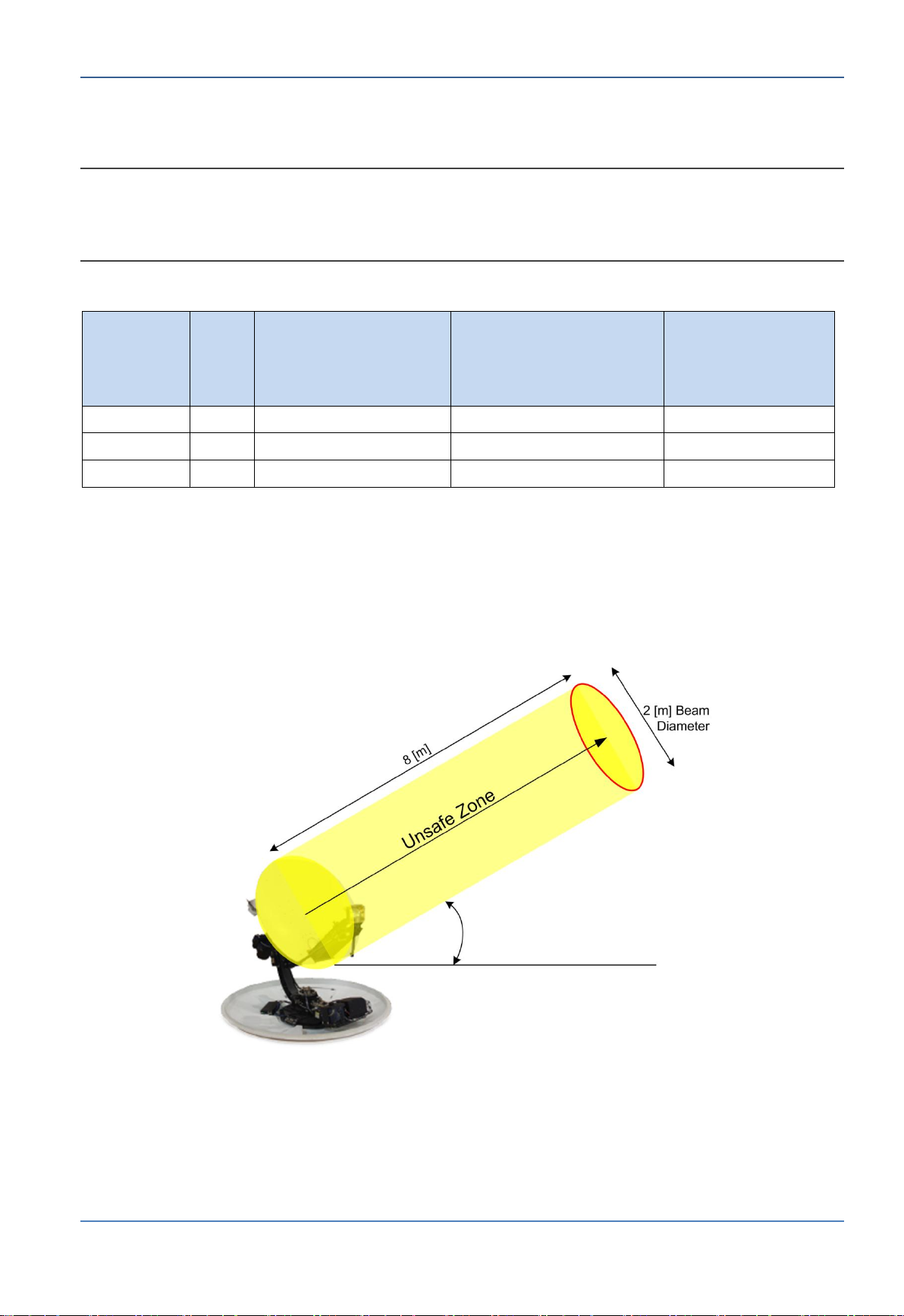
OceanTRx™
4-500
BUC
Power
ACGIH, 10mW/cm2
Occupational/Controlled
6 minutes
Averaging Time
Minimum Distance (m)
ICNIRP, 5mW/cm2
Occupational/Controlled
6 minutes
Averaging Time
Minimum Distance (m)
ICNIRP, 1mW/cm2
General/Uncontrolled
Inapplicable
Averaging Time
Min. Distance (m)
Ku-Band
8W
Radome
Radome
8.0
Ku-Band
16W
Radome
Radome
12.0
Ku-Band
25W
Radome
Radome
18.0
Radiation Safety
NOTE: The Minimum Distances in the table are calculated according to ACGIH (American Conference
of Governmental Industrial Hygienists), and ICNIRP (International Commission on Non-Ionizing
Radiation Protection), which is also adopted by FCC. (See 47 CFR §§2.1091 and 2.1093 on sourcebased time-averaging requirements for mobile and portable transmitters.)
Table 1-1: Safety Distances
The following figure illustrates the safety zones for the OceanTRxTM4-500 system.
OceanTRxTM4-500 Installation and Operations Manual V


Table of Contents
1 Introduction ....................................................................................... 1-1
1.1 About Orbit .................................................................................. 1-2
1.2 About OceanTRx
1.3 OceanTRx™4 Key Features and Advantages ..................................... 1-5
1.4 System Architecture for Standard Topology ...................................... 1-7
1.5 Dual System Topologies ................................................................. 1-8
1.6 Ku-Band BUC Configurations .......................................................... 1-9
1.7 Control and Monitoring ................................................................ 1-10
2 System Description ............................................................................ 2-1
2.1 System RF Layout ......................................................................... 2-2
2.2 Above Deck Equipment (ADE) - Antenna Unit ................................... 2-3
2.3 Central Control Unit (CCU) ............................................................. 2-4
TM
4-500 Ka Band Inherent Support ......................... 1-3
2.4 Dual System Selector (DSS) ........................................................... 2-6
3 Pre-Installation Requirements ........................................................... 3-1
3.1 System Physical Specifications ........................................................ 3-2
3.2 Overview of the Pre-installation Requirements .................................. 3-2
3.3 Location for ADE ........................................................................... 3-4
3.3.1 Surface Stability .................................................................. 3-4
3.3.2 Location Criteria ................................................................... 3-4
3.4 Radome Support (Mast) Requirements ............................................. 3-5
3.4.1 Support Structure Minimum Requirements .............................. 3-6
3.4.2 Example of Mast Design ........................................................ 3-7
3.4.3 Mounting Surface Layout ....................................................... 3-8
3.5 Crane and Harness Specifications .................................................. 3-10
3.6 Main Power Cabling and UPS Guidelines ......................................... 3-11
3.6.1 Power Requirements ........................................................... 3-11
3.6.2 Cabling Guidelines .............................................................. 3-11
3.7 Verify Tx/Rx Path Gain Budgets .................................................... 3-11
3.7.1 OceanTRx4-500 Single System Configuration ........................ 3-15
3.7.2 OceanTRx4-500 Dual System Configuration ........................... 3-19
3.8 Pre-Installation Checklist .............................................................. 3-25
4 Unpacking and Mounting .................................................................... 4-1
4.1 Unpacking the System ................................................................... 4-2
4.1.1 Crate Dimensions ................................................................. 4-2
4.1.2 Crate Inspection and Unpacking ............................................. 4-3
4.2 Mounting ADE ............................................................................... 4-4
4.2.1 Securing and Lifting Antenna System ...................................... 4-4
4.2.2 Mounting and Securing onto the Support Structure (e.g. Mast) .. 4-6
Ocean TRx™ 4500 Installation and Operations Manual VII

Contents
5 Installation Procedure ....................................................................... 5-1
5.1 Required Tools .............................................................................. 5-2
5.2 ADE Physical Preparations and Connections ...................................... 5-2
5.2.1 Opening the Hatch ............................................................... 5-3
5.2.2 Unlocking the Pedestal Axes .................................................. 5-3
5.2.3 ADE to BDE LMR Coaxial RF Cable Connection ......................... 5-4
5.2.4 Power Connections and Power ON .......................................... 5-5
5.3 BDE Installation Procedure ............................................................. 5-6
5.3.1 Rack Installation Criteria ....................................................... 5-6
5.3.2 CCU Installation Procedure .................................................... 5-7
5.3.3 DSS Installation Procedure .................................................... 5-9
6 Navigating the MTSVLink ................................................................... 6-1
6.1 Opening a Session to the CCU ........................................................ 6-2
6.2 Main Screens ................................................................................ 6-4
6.2.1 Startup Screen .................................................................... 6-5
6.2.2 Basic Screen ........................................................................ 6-6
6.2.3 Operation Screen ................................................................. 6-8
6.3 Saving Configuration changes ....................................................... 6-10
6.4 Shortcuts ................................................................................... 6-11
6.5 Configuring the Display ................................................................ 6-12
7 Setup Procedure ................................................................................ 7-1
7.1 Overview of the Commissioning Procedure ....................................... 7-2
7.2 Compass Input Configuration .......................................................... 7-2
7.2.1 Selecting Compass Type ....................................................... 7-2
7.2.2 Set Compass Communication Parameters ................................ 7-3
7.2.3 Setting Ship’s Heading Manually ............................................ 7-5
7.3 Selecting a Satellite ....................................................................... 7-5
7.3.1 Loading a Satellite List File .................................................... 7-6
7.3.2 Manually Defining a Satellite .................................................. 7-7
7.3.3 Defining Channels (Tracking Signals) ...................................... 7-8
7.3.4 Selecting the Desired Satellite and Channels ......................... 7-10
7.4 Perform Compass Offset .............................................................. 7-11
7.5 Setup Blockage Zone ................................................................... 7-15
7.6 Acquire Satellite and Verify AGC ................................................... 7-18
7.7 OpenAMIP Connection – Optional for Idirect Modems ....................... 7-19
7.8 CPI and 1dBcP Compression Point Test .......................................... 7-20
7.9 Configure Modem and Verify Rx Lock ............................................. 7-21
7.9.1 Satellite Validation ............................................................. 7-21
7.9.2 Fine Adjustment (1dBc) ...................................................... 7-22
7.10 Submitting the Commissioning Checklist ........................................ 7-23
8 System Operation .............................................................................. 8-1
VIII Ocean TRx™ 4500 Installation and Operations Manual

8.1 System Operation Modes ............................................................... 8-2
8.1.1 Operating Modes Menu Options .............................................. 8-2
8.1.2 Acquire Mode ....................................................................... 8-3
8.1.3 Acquire Satellite Preset Mode ................................................. 8-3
8.1.4 Step-Track Mode .................................................................. 8-4
8.1.5 Peak Mode .......................................................................... 8-4
8.1.6 Point to Satellite Mode .......................................................... 8-4
8.1.7 Satellite Preset Mode ............................................................ 8-5
8.1.8 Search Mode ....................................................................... 8-5
8.1.9 Stand-by Mode .................................................................... 8-6
8.1.10 Manual Mode .................................................................... 8-6
8.1.11 Stow Mode ....................................................................... 8-7
8.1.12 Test Trajectory Mode ......................................................... 8-8
8.1.13 Program Route Mode ......................................................... 8-9
8.1.14 Acquire Program Track Mode .............................................. 8-9
Contents
8.2 Satellite Database Management ...................................................... 8-9
8.2.1 Configuring the Satellite Database .......................................... 8-9
8.2.2 Filtering the View of Available Satellite Definitions .................. 8-13
8.2.3 Managing the Satellite Database .......................................... 8-13
8.3 Manual Input to the System ......................................................... 8-16
8.3.1 Setting the AGC Threshold .................................................. 8-16
8.3.2 Setting the Ship’s Heading .................................................. 8-17
8.3.3 Setting the GPS Position ..................................................... 8-18
8.4 Rebooting the ACU ...................................................................... 8-19
8.5 Configuring Host Hardware Interfaces ............................................ 8-19
8.5.1 Host Hardware Interface Dialog ........................................... 8-19
8.5.2 Compass Configuration ....................................................... 8-20
8.5.3 Viewing Additional Modem Parameters .................................. 8-22
8.5.4 Configuring IRD Signal Lock ................................................ 8-23
8.5.5 Configuring the GPS Output Hardware Interface ..................... 8-24
8.6 Configuring the Cease Tx Function ................................................ 8-25
8.6.1 Tx Chain Windows .............................................................. 8-26
8.7 Configuring the Restart Mode ....................................................... 8-28
8.8 Configuring AGC Threshold ........................................................... 8-29
8.9 Configuring the NBR .................................................................... 8-30
8.10 System Constellation and Communication Parameters ..................... 8-31
9 Monitoring and Analysis Tools............................................................ 9-1
9.1 Spectrum Analyzer Tool ................................................................. 9-2
9.1.1 Navigating the Spectrum Analyzer Tool ................................... 9-3
9.1.2 Acquisition Criteria ............................................................... 9-5
9.1.3 Configuring the Display ......................................................... 9-6
9.1.4 Running a Measurement ....................................................... 9-7
OceanTRxTM4-500 Installation and Operations Manual IX

Contents
9.2 Graphics Data Logger .................................................................. 9-10
9.2.1 Using the Graphic Data Logger............................................. 9-10
9.2.2 Configuring the Graphic Data Logger .................................... 9-10
9.2.3 Logging Data with the Graphic Data Logger ........................... 9-11
9.2.4 Analyzing and Saving Logger Data ....................................... 9-12
9.3 Calibrating and Activating Noise Floor Correction............................. 9-14
9.3.1 Calibrating the Noise Floor .................................................. 9-14
9.3.2 Typical Noise Floor Curves ................................................... 9-16
9.3.3 Activating Noise Floor Correction .......................................... 9-18
9.4 Monitoring System Voltage and Temperature Test Points ................. 9-19
9.5 Monitoring the MtsVLink Work Session ........................................... 9-19
9.6 System Messages Log .................................................................. 9-20
9.7 Downloading the Status Dump File ................................................ 9-21
9.8 Viewing Software Version Details .................................................. 9-22
Appendix A: Technical Specifications ....................................................... A-1
Appendix B: MIB for the Antenna Control Unit ......................................... B-1
Appendix C. Status Messages .................................................................. C-1
Messages (Informative) ....................................................................... C-1
Warning Messages ............................................................................... C-2
Error Messages ................................................................................... C-4
Appendix D: BDE Equipment Pinout ......................................................... D-1
Modem M&C Connector pin-out ............................................................. D-1
SYNCHRO & SBS Compass Connector pin-out ......................................... D-1
NMEA Compass Connector pin-out ......................................................... D-3
Appendix E: Preparing the ADE-BDE Cable .............................................. E-1
Appendix F: Pre-Installation Checklist..................................................... F-4
Mechanical Stability .............................................................................. F-4
Maintenance Access .............................................................................. F-4
Line of Sight ........................................................................................ F-5
Other Considerations ............................................................................ F-5
Mounting Surface ................................................................................. F-5
Appendix G: Installation Checklist ........................................................... G-1
Please check the state of the G-Shock detectors and mark their color: ....... G-1
Crate Visual Inspection ........................................................................ G-2
Appendix H: Commissioning Checklist ..................................................... H-1
Mechanical Stability ............................................................................. H-1
Maintenance Access ............................................................................. H-1
Line of Sight ....................................................................................... H-1
Other Considerations ........................................................................... H-2
Mounting Surface ................................................................................ H-2
X Ocean TRx™ 4500 Installation and Operations Manual

1 Introduction
This chapter introduces the OceanTRx
The following information is included in this chapter:
1.1 About Orbit .................................................................................. 1-2
1.2 About OceanTRx
1.3 OceanTRx™4 Key Features and Advantages ..................................... 1-5
1.4 System Architecture for Standard Topology ...................................... 1-7
1.5 Dual System Topologies ................................................................. 1-8
1.6 Ku-Band BUC Configurations .......................................................... 1-9
1.7 Control and Monitoring ................................................................ 1-10
TM
4-500 Ka Band Inherent Support ......................... 1-3
TM
4-500 system.
Ocean TRx™ 4500 Installation and Operations Manual 1-1
About Orbit Introduction
1.1 About Orbit
ORBIT is a global provider of highly engineered mission-critical communications systems
and solutions for aerospace, maritime and earth observation applications in commercial,
defense and homeland security markets.
ORBIT has developed, manufactured, delivered and supports thousands of mission critical
systems worldwide since 1970.
Our portfolio includes Mobile Satellite Communications systems (Satcom), which are
deployed on thousands of marine (over 3,500 installation worldwide), airborne and
ground platforms worldwide, Communications Management Systems (CMS), and Tracking
& Telemetry solutions (T&T).
ORBIT’s customers include military users from more than 30 armed forces around the
world, major integrators, communications service providers and earth observation
organizations. ORBIT was selected as the Satcom providers of more than 20 leading
Navies worldwide.
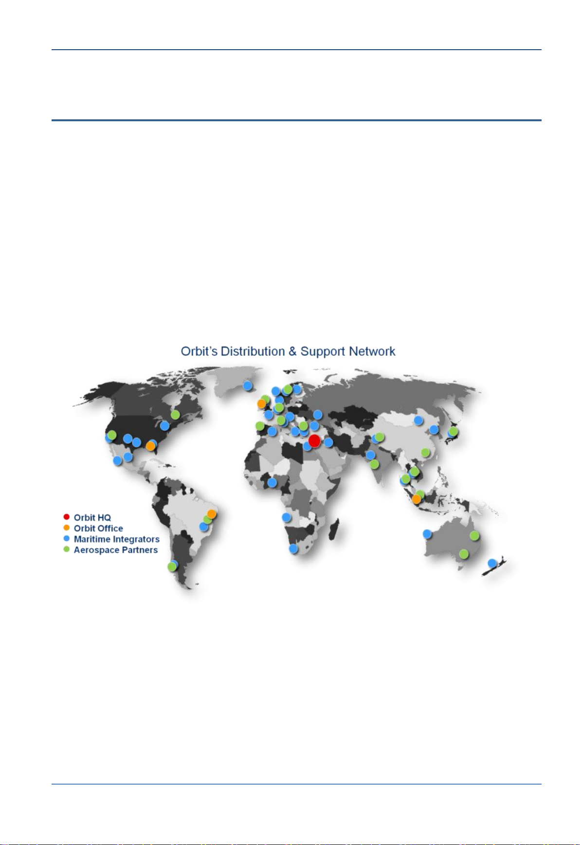
Figure 1-1: Orbit’s Distribution and Support Centers
ORBIT is a public company, traded in the Israeli stock exchange, with a headquarter in Israel and
international sales and customer support network that includes the United States, Europe, Brazil and
Singapore, in addition to its international technical service centers located around the world.
1-2 Ocean TRx™ 4500 Installation and Operations Manual

Introduction About OceanTRxTM 4-500 Ka Band Inherent Support
1.2 About OceanTRx
OceanTRxTM4-500 is part of OceanTRx4™product family. OceanTRx™4 is a revolutionary
compact, lightweight maritime antenna system. (Other typical solutions require 88%
more deck space and can be up to 40% heavier).
OceanTRx™4 innovative platform supports a variety of 1.15m stabilized maritime
antenna system configurations in the Ku and Ka bands. As a common platform, it is
inherently designed to accommodate the current and future needs of the maritime
market. Built to empower mission and business-critical applications, OceanTRx™4
features outstanding RF performance, system availability and dynamic response under
virtually any sea conditions. As such, the system is an optimal solution for the broadband
communications needs of myriad maritime platforms such as frigates, container ships,
offshore drilling support vessels, mega yachts, and other vessels.
The 500 Series features built-in Ka band fully compatible design to ensure smooth
migration to future high-speed Ka band services - for the entire Ka band range - using
GEO and MEO satellites. OceanTRx™4-500 provides multi-band frequency support for Ku,
Ka and X bands*, based on field exchangeable kits.
* Field upgradable upon release and customization
4-500 Ka Band Inherent Support
TM
Figure 1-2: OceanTRxTM4 Antenna-to-Radome
OceanTRxTM4-500 Installation and Operations Manual 1-3
About OceanTRxTM 4-500 Ka Band Inherent Support Introduction
This system consists of two main assemblies:
Above Deck Equipment (ADE) - antenna system
Below Deck Equipment (BDE) - Control and management unit. Installed in a 19” rack
below deck and connected to the ship’s communication and navigational (GPS)
infrastructure
Figure 1-3: OceanTRxTM4-500 Antenna-to-Radome
1-4 Ocean TRx™ 4500 Installation and Operations Manual

Introduction OceanTRx™4 Key Features and Advantages
1.3 OceanTRx™4 Key Features and Advantages
Designed for Reliability and Durability - designed to withstand the most
demanding sea conditions.
OceanTRx™4 features a low-intensity electro-mechanical design and complies with the
most stringent environmental standards for shocks, bumps and vibrations – including
MIL-STD-167-1A and DNV 2.4 Class C, as well as IEC-60721 and designed to MILSTD-901D (Grade B) standards in its enhanced configuration for defense and offshore
O&G applications.
Rapid Low-Cost Installation - OceanTRx™4 is quick and simple to install, since it
does not require balancing and uses a single cable for below-deck connectivity.
The system is shipped fully assembled and pre-tested over satellite. It can be installed
in a mere matter of hours, dramatically shortening your installation time as compared
to equivalent solutions.
Balance Free System Installation/Upgrades/Maintenance - Balance Free
system both during installation and upgrades.
Lowers cost of ownership as no periodic visits are required for balancing.
Enhanced on-board Serviceability and Platform Commonality for Cost-
Effective Operations - highly accessible pedestal design, enabling convenient
service support and field upgrade process.
As part of ORBIT’s new OceanTRx™ product line, OceanTRx™4-500 shares common
electronic field-replaceable units (FRUs) with ORBIT’s OceanTRx™4 systems, allowing
for lower cost of ownership, easier maintenance support, and shorter response times.
Superior Tracking Performance - Orbit's superior tracking performance results with
better RF performance and signal stability. Tracking performance is critical parameter
when operating large dish and when operating at high frequencies such as Ku and Ka
bands.
For over 30 years, Orbit designs and manufactures elite tracking products with best in
class tracking technology. This technology is used for its vast product portfolio such as
missile and aircrafts tracking which have the most demanding tracking requirements.
Superior Performance & Air-Time Efficiency - outstanding RF performance,
combined with the modem’s adaptive coding modulation (ACM) technology and the
superior tracking performance, improves satellite resource usage and ensures alwayson connectivity on the fringes of satellite coverage.
High versatility and multiple configurations - built-in support for a wide range of
configurations with different RF packages (Ku, Ka*) and BUC power levels (up to 25W
without cooling) facilitates field upgradability without the need for accurate balancing.
The system supports dual or triple system operation and comes with either a white or
gray radome.
* Field upgradable upon release and customization
OceanTRxTM4-500 Installation and Operations Manual 1-5

OceanTRx™4 Key Features and Advantages Introduction
Field Upgradability – system is field upgraded between Ku-band and Ka-band*.
OceanTRx™4 is designed to simultaneously support two BUC modules for rapid field
upgrade process.
Upgrades (configuration dependent) require changing a number of modules: Feed
and LNB, BUC and cables. If two BUC modules are installed in the system, only the
Feed+LNB needs changing.
* Field upgradable upon release and customization
Seamless Global Coverage - OceanTRx™4 ensures worldwide connectivity by
supporting the full range of Ku or Ka band frequencies using optional RF feeds for GEO
or MEO satellites.
Operating with satellites across geographical regions, OceanTRx™4 delivers seamless
global coverage via automatic beam switching (ABS) achieved through the industrystandard OpenAMIP and ROSS Open Antenna Management (ROAM) protocols.
Electrically switchable polarization facilitates satellite switching and increases system
versatility.
Remote Connection, Monitoring, Diagnostics and Troubleshooting - advanced
remote monitoring capabilities allow complete replication of the system interface to
any remote PC.
Combined with an inherent logger and spectrum analyzer, it enables off-site
technicians to remotely monitor and operate the system, or carry out troubleshooting
and diagnostics as if they were on the ship, thereby reducing operational costs. Open
platform design supports the use of SNMP for carrying out network and system
management, while enabling system integration with any network operations center
(NOC). Secured remote connection is available for software upgrades.
Strict Regulatory Compliance and Certifications
OceanTRx™4 complies with industry regulations and standards for X, Ku and Ka bands
including ITU, FCC, ETSI, EutelSat, IntelSat, ANATEL regulations (for Ku & Ka Bands),
as well as “STANAG 4484” and “Skynet 5-Paradigm”(for X Band).
World-Class Customer Support - five regional service centers located around the
globe, ORBIT’s trained support engineers/technicians are available 24x7 to handle the
immediate needs of customers worldwide.
A global inventory replenishment system ensures efficient spare parts distribution
across regions. By using remote connection for troubleshooting and diagnostics,
ORBIT expedites service support and enhances overall cost-effectiveness for its
customers.
1-6 Ocean TRx™ 4500 Installation and Operations Manual
Introduction System Architecture for Standard Topology
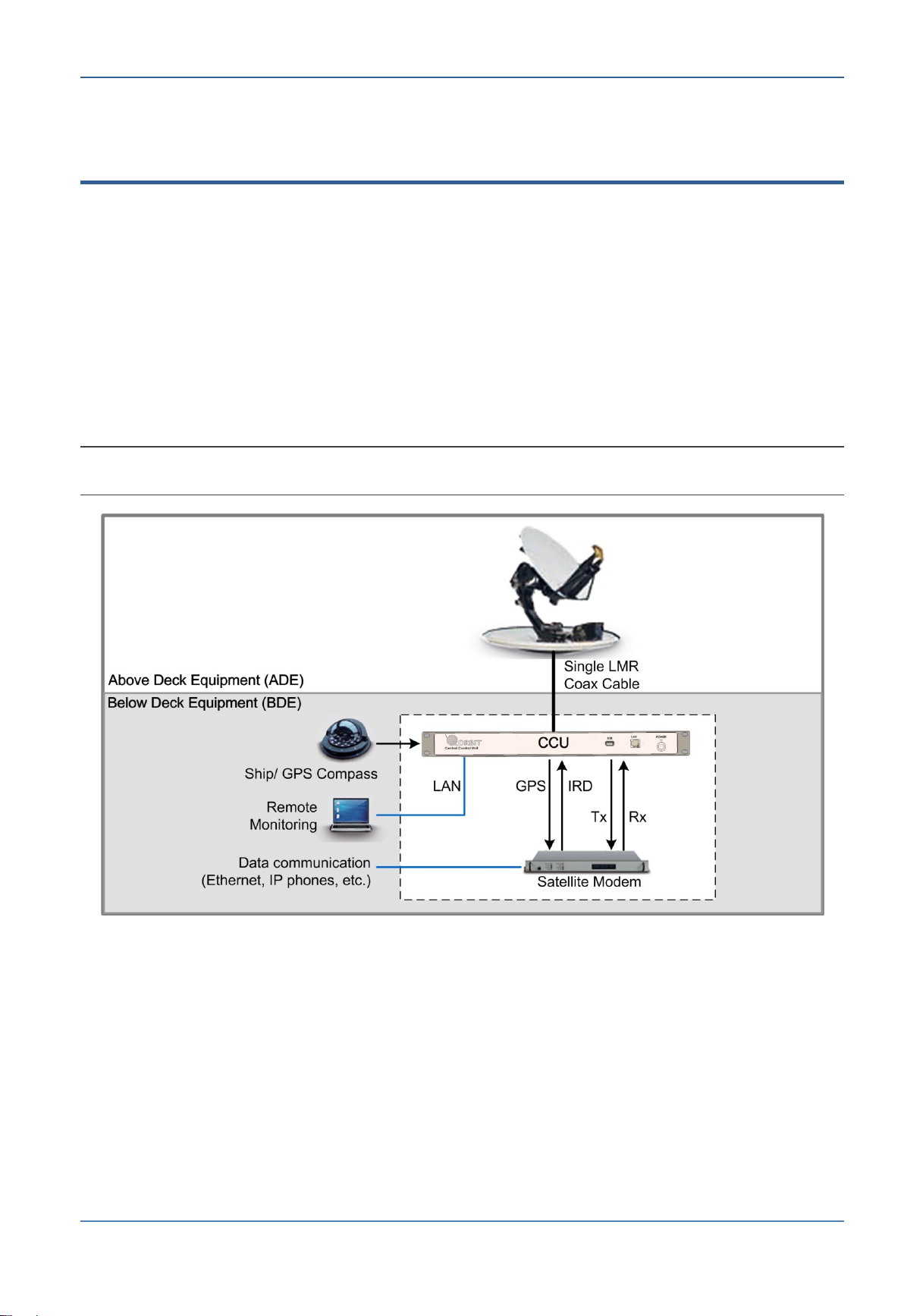
1.4 System Architecture for Standard Topology
The OceanTRx™4-500 system consists of the following main elements:
Antenna system – mounted above deck as a single unit, the system is designed to
operate with a specific satellite band. It receives and transmits high-frequency signals
from and to the satellite.
Control and Communication Unit (CCU) - installed below deck in a standard rack, this
unit interfaces to the antenna system (via a single cable) and to the ship’s
communication and navigational infrastructure.
The antenna system interfaces to the CCU via a single coaxial cable. The CCU acquires
signals from the ship’s compass and satellite modem for integration with the satellite
data.
NOTE: The illustration below provides an overview of the connections. It does not include the power
cables and other specific connections.
Figure 1-4: Single System Configuration Architecture Overview
OceanTRxTM4-500 Installation and Operations Manual 1-7
Dual System Topologies Introduction
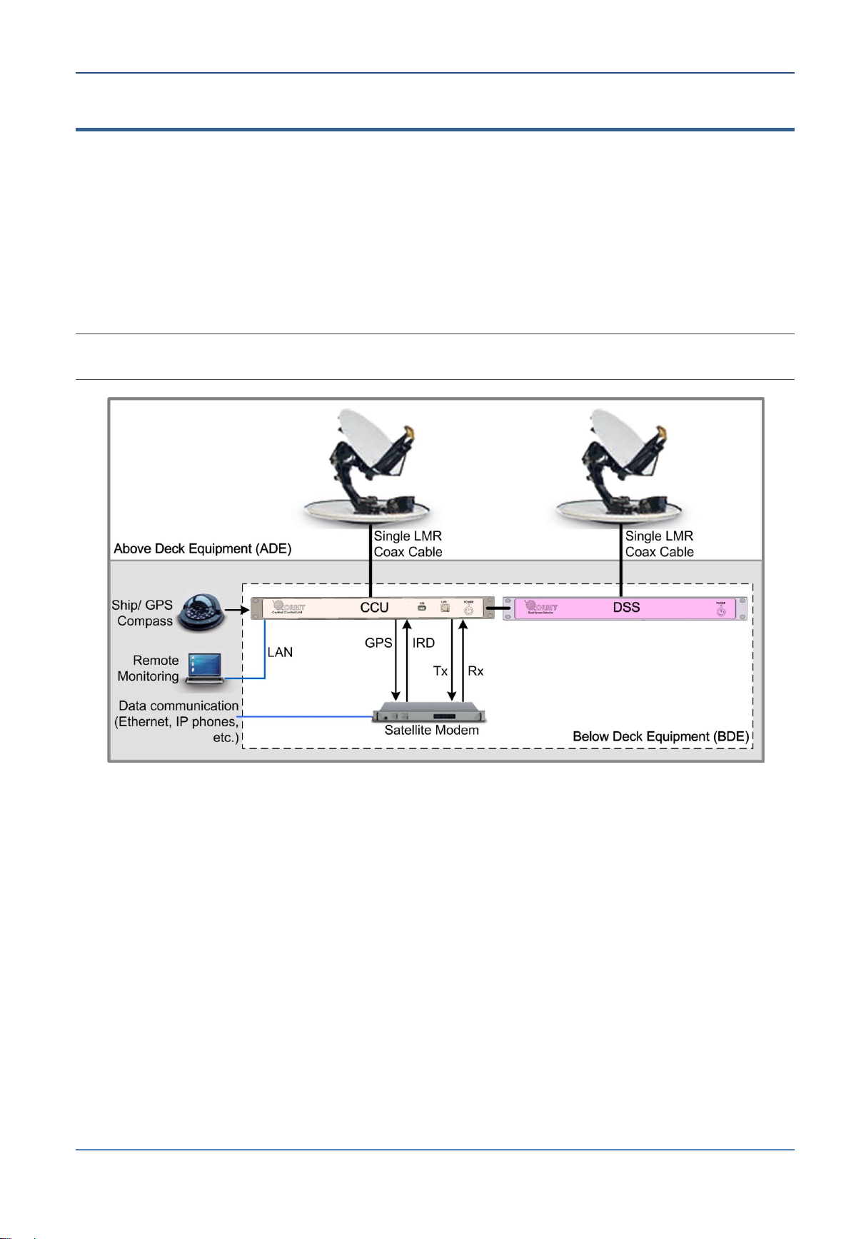
1.5 Dual System Topologies
Dual system topologies are used in scenarios where installation space and line-of-sight to
the sky/satellite is limited. In this type of scenario, the installation of two smaller antenna
systems instead of one larger antenna system is recommended.
In a dual-system topology, two smaller antenna systems (installed above deck), are
connected to the management equipment (located below deck), for single-source
management.
This type of installation utilizes a Dual-System-Selector (DSS) to provide single-source
management of both antenna assemblies via a single CCU.
NOTE: The illustration below provides an overview of the connections. It does not include the power
cables and other specific connections.
Figure 1-5: Dual System Configuration Architecture Overview
1-8 Ocean TRx™ 4500 Installation and Operations Manual

Introduction Ku-Band BUC Configurations
BUC/LNB
Band
Power
BUC Agilis 8W
Ku
8W
BUC Wavestream 16W
BUC Agilis 16W
Ku
Ku
16W
16W
BUC Wavestream 25W
BUC Agilis 25W
Ku
Ku
25W
25W
BUC Wavestream 40W
Ku
40W
1.6 Ku-Band BUC Configurations
Specific configurations of OceanTRx™4-500 system provide support for continuous
communication on global voyages via automatic beam switching between satellites. This
feature supports a wide variety of configurations that cover Global-Ku Band and future
Ka/X Band requirements and consists of the following components:
Global LNB – Covers the full Ku-Band receive range via selection of one of four LO
(local oscillator) ranges.
Cross Polarization Feed
The OceanTRxTM4-500 system is available with a wide variety of Ku-Band BUCs that work
with linear RF feeds. Antenna polarization is electrically switchable for Ku-Band feeds.
The OceanTRxTM4-500 system supports a two-BUC configuration with field replaceable
feeds, enabling easy switching between Ku-Feeds, and a dual system configuration (two
systems controlled from a single interface).
NOTE: The configurations below comprise fully integrated and operational systems including BUC and
dual or quad-band LNB. Available with linear polarization or Co-Cross Polarization Feed. Other
configurations may be available on request.
Table 1-1 BUC LNB Band Power
OceanTRxTM4-500 Installation and Operations Manual 1-9
Control and Monitoring Introduction
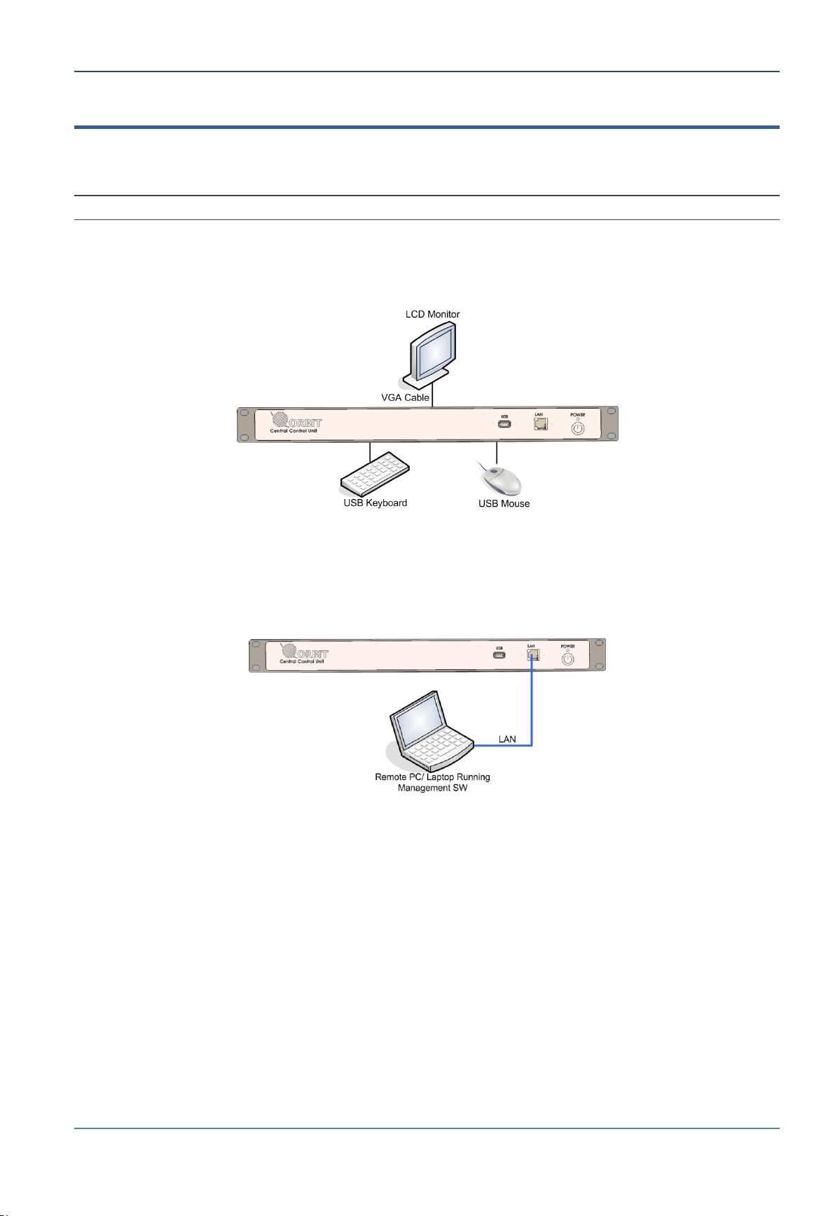
1.7 Control and Monitoring
The system can be managed by opening a local or remote session to the CCU. The CCU
supports Ethernet and USB connections on the front and on the rear panel.
NOTE: Optional - foldable LCD and 1U keyboard can be ordered from Orbit.
Local management – local connection to the CCU, where the CCU operates as the
management station and external peripherals (keyboard, mouse, screen) are
connected to the CCU. Management is performed via MtsVLink management SW.
Figure 1-6: Local Management
Remote management – opening a remote CCU session a standard MIB application or
MtsVLink: in-band (via modem), out-band (via L-band modems such as Fleetboard
band, airband)
Figure 1-7: Remote Management
1-10 Ocean TRx™ 4500 Installation and Operations Manual

2 System Description
The following information is included in this chapter:
2.1 System RF Layout ......................................................................... 2-2
2.2 Above Deck Equipment (ADE) - Antenna Unit ................................... 2-3
2.3 Central Control Unit (CCU) ............................................................. 2-4
2.4 Dual System Selector (DSS) ........................................................... 2-6
Ocean TRx™ 4500 Installation and Operations Manual 2-1
System RF Layout System Description
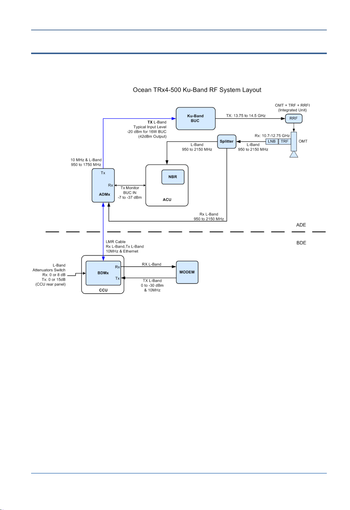
2.1 System RF Layout
The following figure shows the frequencies and RF measurements at various points in the
system.
Figure 2-1: OceanTRxTM4-500 RF Layout
2-2 Ocean TRx™ 4500 Installation and Operations Manual
System Description Above Deck Equipment (ADE) - Antenna Unit
Radome
Azimuth Axis
Radome Base
Hatch in
Radome Base
Tilt axis
Elevation axis
Marker location
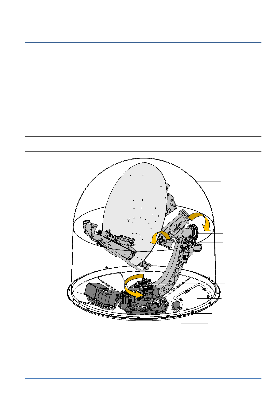
2.2 Above Deck Equipment (ADE) - Antenna Unit
The ADE consists of the antenna system, completely covered and protected by a Radome.
Maintenance access is provided by a service hatch in the Radome base.
The antenna system supports three rotary axes:
Azimuth axis – provides continuous unlimited 360 rotation.
Tilt axis – provides ±70 of horizontal rotation.
Elevation axis – provides 150 of vertical rotation (-30 to +120).
These three axes and their range of movement allow continuous focus on the satellite
under all specified sea conditions without exceeding the system’s mechanical limits or
encountering geometrical keyholes.
In addition to the above axes, an additional Polarization Skew axis provides 230 of
rotation (±115).
NOTE: The marker provides a reference to the optimal installation position – it should be (as much as
possible) in line with the ship’s vertical axis.
OceanTRxTM4-500 Installation and Operations Manual 2-3
Figure 2-2: Above Deck Equipment (ADE)
Central Control Unit (CCU) System Description
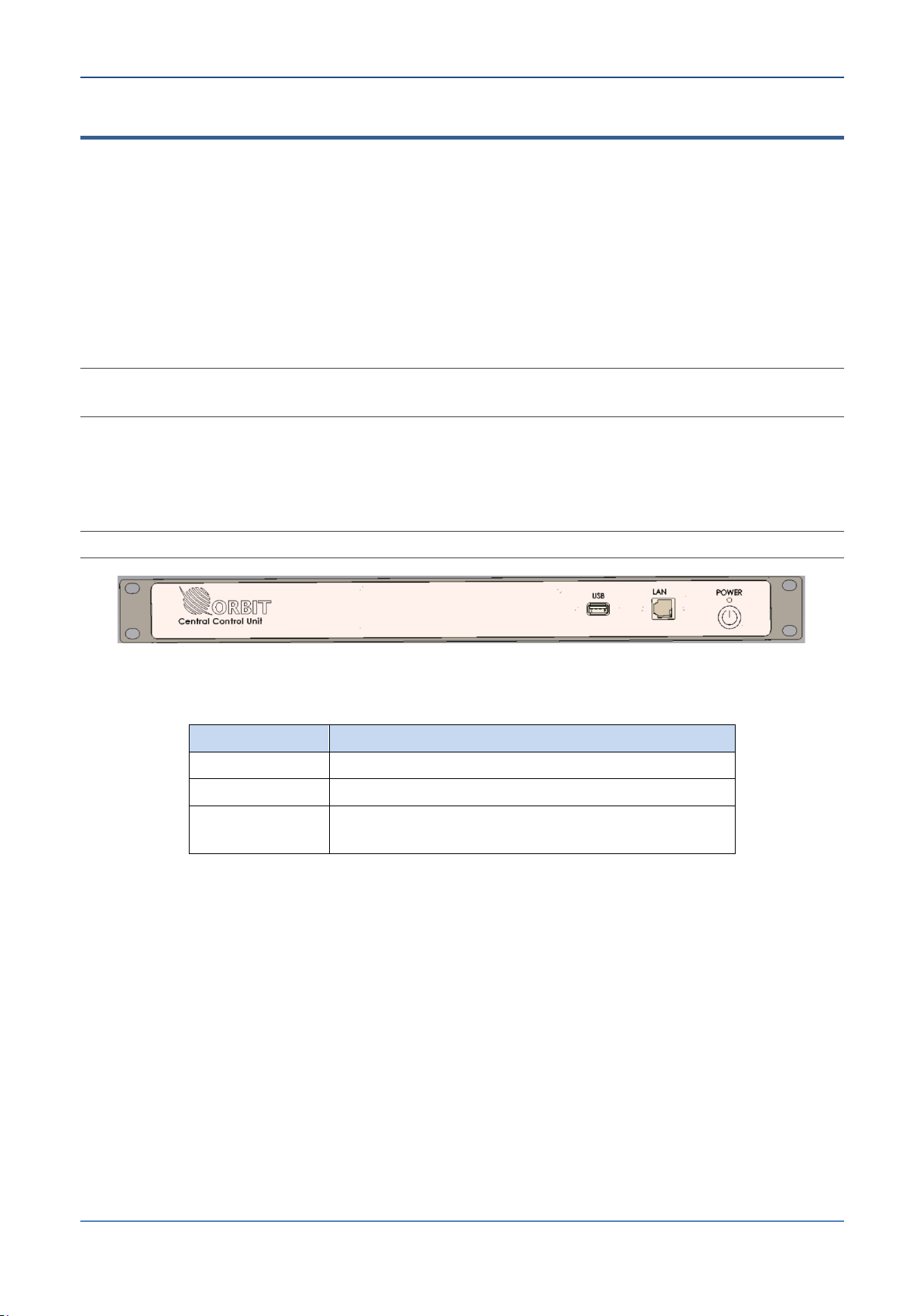
Interface
Function
USB
General purpose USB port
LAN
Network management connection.
POWER
On/Off (soft) switch. (Main power ON/OFF
switch is located on the rear panel).
2.3 Central Control Unit (CCU)
The CCU is installed below deck, in a 19” rack. It provides interfaces to the following:
ADE - Antenna unit
Ship’s compass
Satellite modem
Communication infrastructure
The CCU implements the required IF and RF conversion functions, and supports both local
and remote system management and control functionality via MtsVLink management
software installed on the CCU.
NOTE: There are two CCU models: with and without 10MHz reference signal. Models without the
reference signal require an external 10MHz reference signal from the ship’s modem.
2.3.1.1 CCU Front Panel
The CCU front panel contains the On/Off (soft) switch, a connection to the LAN and a USB
port.
NOTE: Additional Ethernet and USB connections are available on the rear panel.
Figure 2-3: CCU Front Panel
Table 2-1: CCU Front Panel Interfaces
2-4 Ocean TRx™ 4500 Installation and Operations Manual
System Description Central Control Unit (CCU)
Interface
Function
ADE
N-Type. Connection to ADE via ADE-BDE coaxial cable
AUX-IF1/IF2
F-Type. For CCU with 10MHz reference signal.
Connection to ship’s modem.
Tx/Rx
F-Type. For CCU without 10MHz reference signal.
Connection to ship’s modem.
LAN (2 ports)
General purpose Ethernet ports
USB (2 ports)
General purpose USB ports
VGA
HD15. External video monitor connection.
Used in conjunction with keyboard and mouse (USB
connections) for direct management connection to the CCU.
AUX COM
D-Type (15-pin).
Relevant for dual system configurations. Connects to the DSS.
MODEM
D-Type (9-pin). Modem management and control, M&C port
connections.
Optional: connection to IRD, GPS output etc.
COMPASS
Compass interfaces. Connect the compass to the connector
corresponding to the compass type operating on your ship:
NMEA: D-Type (9-pin)
SYNCHRO or SBS: D-Type (25-pin)
POWER (inlet)
Male. Connects to the mains AC power
POWER (switch)
Power ON/OFF
ATTENUATION Rx*
Rx attenuation ON or OFF (8dB Attenuation)
ATTENUATION Tx*
Tx attenuation ON or OFF (15dB Attenuation)
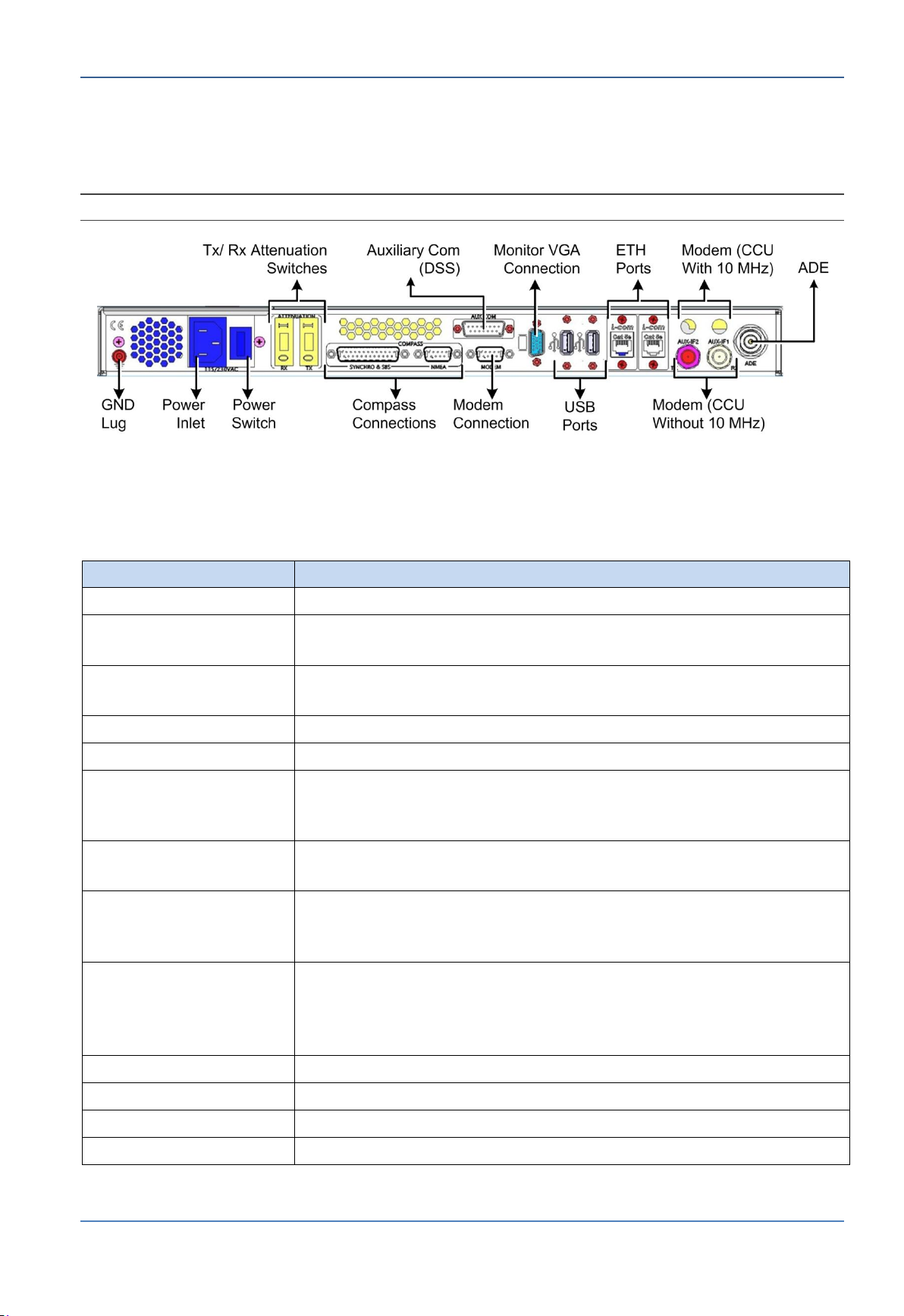
2.3.1.2 CCU Rear Panel
The CCU rear panel contains interfaces to the ADE and to the ship’s communication
equipment.
NOTE: BDE equipment pinouts are provided in Appendix D.
Figure 2-4: CCU Rear Panel
The following table describes the connectors and switches on the rear panel of the CCU.
Table 2-2: CCU Rear Panel Interfaces
*According to cable length.
OceanTRxTM4-500 Installation and Operations Manual 2-5
Dual System Selector (DSS) System Description
Interface
Function
POWER
Power switch. (Main power ON/OFF switch is
located on the rear panel).
2.4 Dual System Selector (DSS)
The DSS is used to implement dual-system configurations (see section 1.5). Both
systems are managed via the CCU. See section 1.5.
The DSS provides interfaces to the following:
Second Antenna unit
CCU for single source management and interface to the ship’s modem
2.4.1.1 DSS Front Panel
The DSS front panel contains the On/Off switch.
Figure 2-5: DSS Front Panel
Table 2-3: DSS Front Panel Interfaces
2-6 Ocean TRx™ 4500 Installation and Operations Manual
System Description Dual System Selector (DSS)
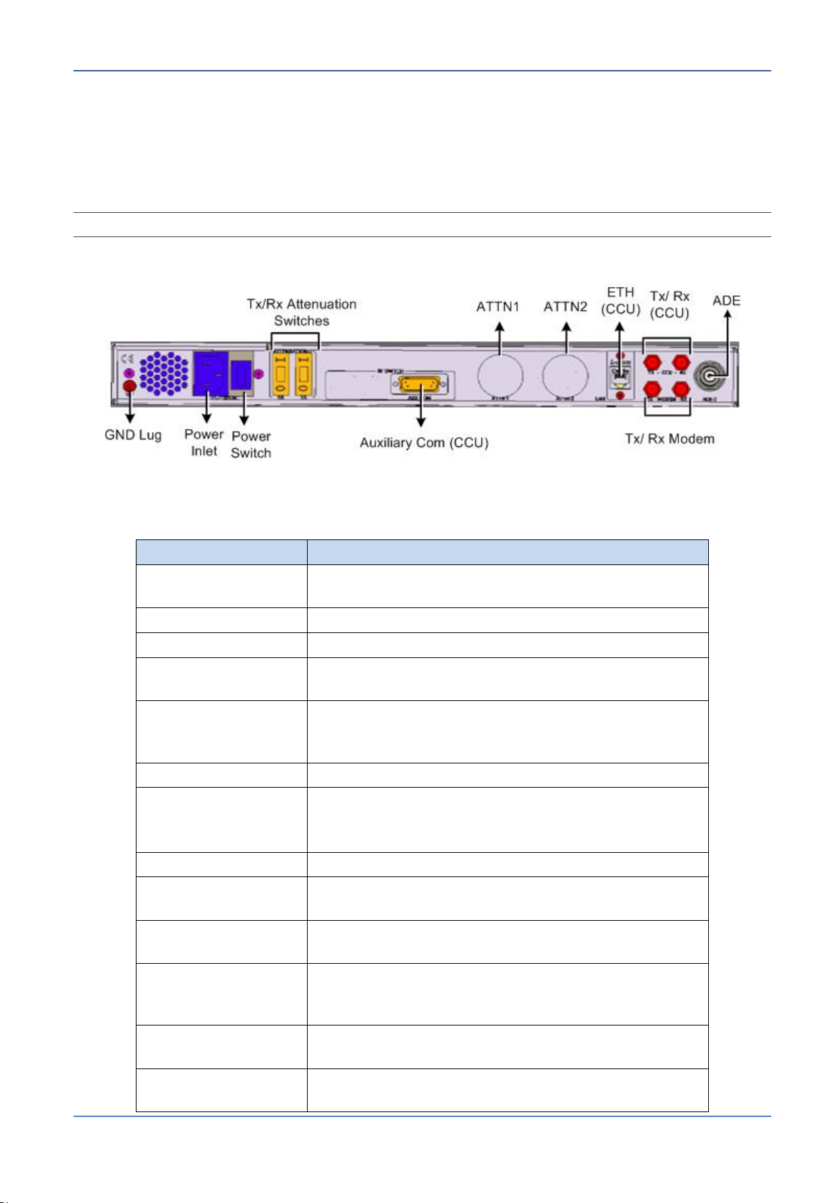
Interface
Function
ADE2
N-Type. Connects to the ADE-BDE coaxial cable
on the second system
CCU - RX
F-Type. Input, connects to the CCU RX port
CCU - TX
F-Type. Output, connects to the CCU TX port
MODEM - RX
F-Type. Output, connects to the CFE modem RX
port
MODEM - TX
F-Type. Input, connects to the CFE modem TX
port in systems with a CCU without 10MHz and to
the CCU AUX-IF2 port with a CCU with 10MHz
LAN
R-J45. Connects to one of the CCU LAN ports
AUX COM
D-Type. 15-pin - passes switching commands
from CCU to the DSS.
Connects to the CCU AUX COM port
POWER
Connects to the mains AC power
POWER
Turns the power to the internal DSS power supply
ON or OFF
ATTN-1
Raises or lowers attenuation of the first system
(attached to the CCU) Tx signal in 1dB steps
ATTN-2
Raises or lowers attenuation of the second
system (attached to the DSS) Tx signal in 1dB
steps
ATTENUATION-2 RX
Turns Rx attenuation of the second system ON or
OFF (8dB Attenuation)
ATTENUATION-2 TX
Turns Tx attenuation of the second system ON or
OFF (15dB Attenuation)
2.4.1.2 DSS Rear Panel Interfaces
The DSS rear panel contains the power interfaces, and connections to the CCU and
second antenna unit (ADE).
NOTE: BDE equipment pinouts are provided in Appendix D.
Figure 2-6: DSS Rear Panel
Table 2-4: DSS Rear panel Interfaces
OceanTRxTM4-500 Installation and Operations Manual 2-7


3 Pre-Installation Requirements
This chapter provides the criteria for choosing the exact installation site for the
satellite and the required installation equipment.
The following information is included in this chapter:
3.1 System Physical Specifications ........................................................ 3-2
3.2 Overview of the Pre-installation Requirements .................................. 3-2
3.3 Location for ADE ........................................................................... 3-4
3.4 Radome Support (Mast) Requirements ............................................. 3-5
3.5 Crane and Harness Specifications .................................................. 3-10
3.6 Main Power Cabling and UPS Guidelines ......................................... 3-11
3.7 Verify Tx/Rx Path Gain Budgets .................................................... 3-11
3.8 Pre-Installation Checklist .............................................................. 3-25
Ocean TRx™ 4500 Installation and Operations Manual 3-1

System Physical Specifications Pre-Installation Requirements
Unit
Weight*/**
Dimensions
Power
Source**
Antenna
System (ADE)
~200Kg/441lb*
Diameter = 1.68
Height 1.69
115/230 VAC
6A/3A
CCU/DSS
-----
1U x 48.26 x 47.4 cm
(h*w*d)
115/230 VAC
1.0A/0.5A
3.1 System Physical Specifications
Table 3-1: System Physical Specifications
* Model dependent
** Varies according to BUC model
NOTE: Since Orbit’s below deck equipment consists only of the CCU (and DSS for dual-system
configurations), most of the information in this chapter describes the pre-installation requirements for
the antenna system.
3.2 Overview of the Pre-installation Requirements
The antenna system and the Radome arrive as a single pre-assembled unit. Using a
crane and harness, the unit is mounted on a prepared support structure (provided by the
customer). A single cable connects between the antenna system and the CCU located
below-deck.
NOTE: For Dual-system assemblies, a single cable connects between the second antenna and the
DSS.
Pre-installation preparations
The antenna system pre-installation procedures consist of the following main phases:
Location - select exact location for the antenna system (section 3.3).
Link budget calculation
Satellite support structure (e.g. mast) - preparing (or verifying existence of) a
Antenna system support structure (section 3.4)
Lifting equipment - you will need a crane and harness – capable of lifting the antenna
system (section 3.5).
All BDE (Below Deck Equipment) is installed in a rack and must have access to
interfaces of relevant devices such as the ship’s compass, GPS and the communication
equipment.
3-2 Ocean TRx™ 4500 Installation and Operations Manual
 Loading...