

Orbit OBR170M Owner's Manual
OBR170M
• Warranty
• Assembly
• Parts
Owner's manual OBR170M
CAUTION: 1. Weight on this product should not exceed 150kg
2 Exercise of a strenuous nature, as is customarily done on this equipment,
Should not be undertaken without first consulting a physician.
No specific health claims are made or implied as they relate to the equipment.
Measurements made by the equipment are believed to be accurate, but only the
measurements of your physician should be relied upon.
IMPORTANT: Read all instruction carefully before using this product. Retain this product owner's
manual for future reference.

1
01
Assembly
PRECAUTIONS
WARNING: This bicycle has been designed and constructed to provide maximum safety. Nevertheless, certain
precautions should be taken when using exercise equipment. Read the whole manual before assembling and using
the bicycle. The following safety precautions should also be observed:
1. Before using the exercise bike, please read all instructions in this manual.
2. It is the responsibility of the owner to ensure that all users of the bike are adequately informed
of all precautions. Use the exercise bike only as described in this manual.
3. Use the bike indoors on a level surface and keep it away from moisture and dust. Place a mat
under the stabilizers to protect the carpet or floor.
4. Inspect and tighten all parts regularly. Replace and worm parts immediately
5. Keep children away from this equipment at all times. DO NOT leave them unsupervised in the room where this
bicycle is kept.
6. Wear appropriate exercise clothing when using the bike. Do not wear loose clothing that could
become caught in the bike.
7. If you feel pain or dizziness while exercising, stop immediately and cool down.
8. The pulse sensor is not a medical device. Various factors including the user’s movement, may
affect the accuracy of the heart rate readings. The Pulse sensor is intended only as an exercise
aid in determining heart rate rends in general.
Pre-assembly notes
OPEN THE BOXES
Make sure to inventory all the parts that are included in the boxes. Check The Hardware Chart
for a full count of the number of parts included for proper assembly.
GATHER YOUR TOOLS
Before starting the assembly of your unit, gather the necessary tools. Having all of the equipment at hand
will save time and make the assembly quick and hassle-free.
CLEAR YOUR WORK AREA
Make sure that you have cleared away a large enough space to properly
assemble the unit. Make sure the space is free from anything that may cause
injury during assembly. After the unit is fully assembled, make sure there is a
comfortable amount of free area around the unit for unobstructed operation.
2
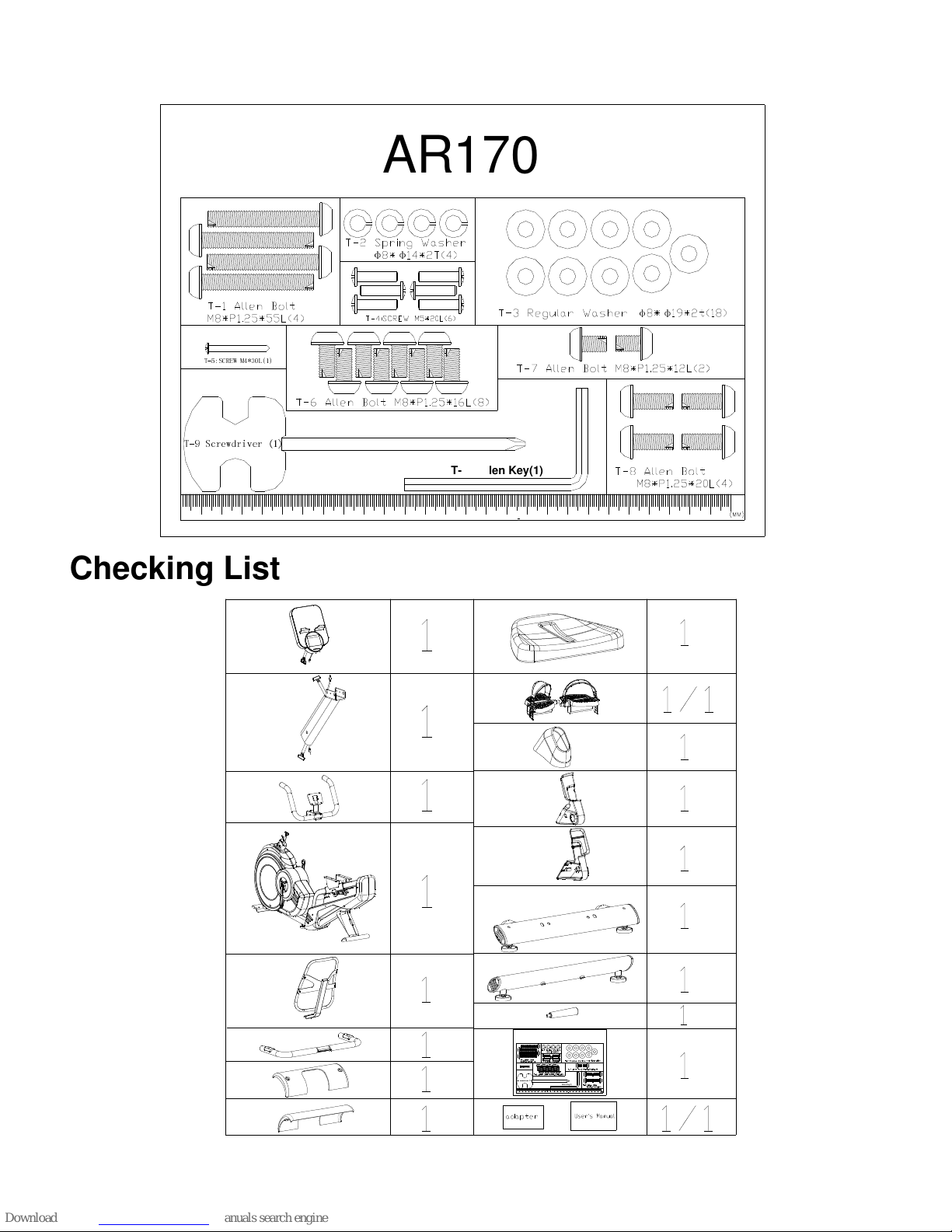
Hardware chart
AR170
φ φ
T-9 Screwdriver (1)
T-10 Allen Key(1)
φ φ
T-5:SCREW M4*30L(1)
Checking List
AR170
φ φ
T-9 Screwdriver (1)
T-10 Allen Key(1)
φ φ
T-5:SCREW M4*30L(1)

3
Part list
Item Description Q'ty
A Computer Set 1 SET
A-1 Computer 1 PCS
A-2 Screw M5 4 PCS
B HBR Post assembly 1 SET
B-1 Handlebar post 1 PCS
B-2 Wire 600mm for post 1 PCS
B-3 Wire 650mm for post 1 PCS
B-4 Screw M8 4 PCS
B-5 Flat washer 2 PCS
B-6 Wave washer 2 PCS
C Front Handlebar assembly 1 SET
C-1 Front Handlebar 1 PCS
C-2 Hand grip 2 PCS
C-3 End cap 2 PCS
D Axle assembly 1 SET
D-1 Axle set 1 PCS
D-2 Hex screw M8 3 PCS
D-3 Pulley 1 PCS
D-4 Bushing 1 PCS
E-2 Spring 1 PCS
E-3 Bearing 6203 2 PCS
E-4 Wave washer 1 PCS
E-5 Flat washer 1 PCS
E-6 C clip 1 PCS
4
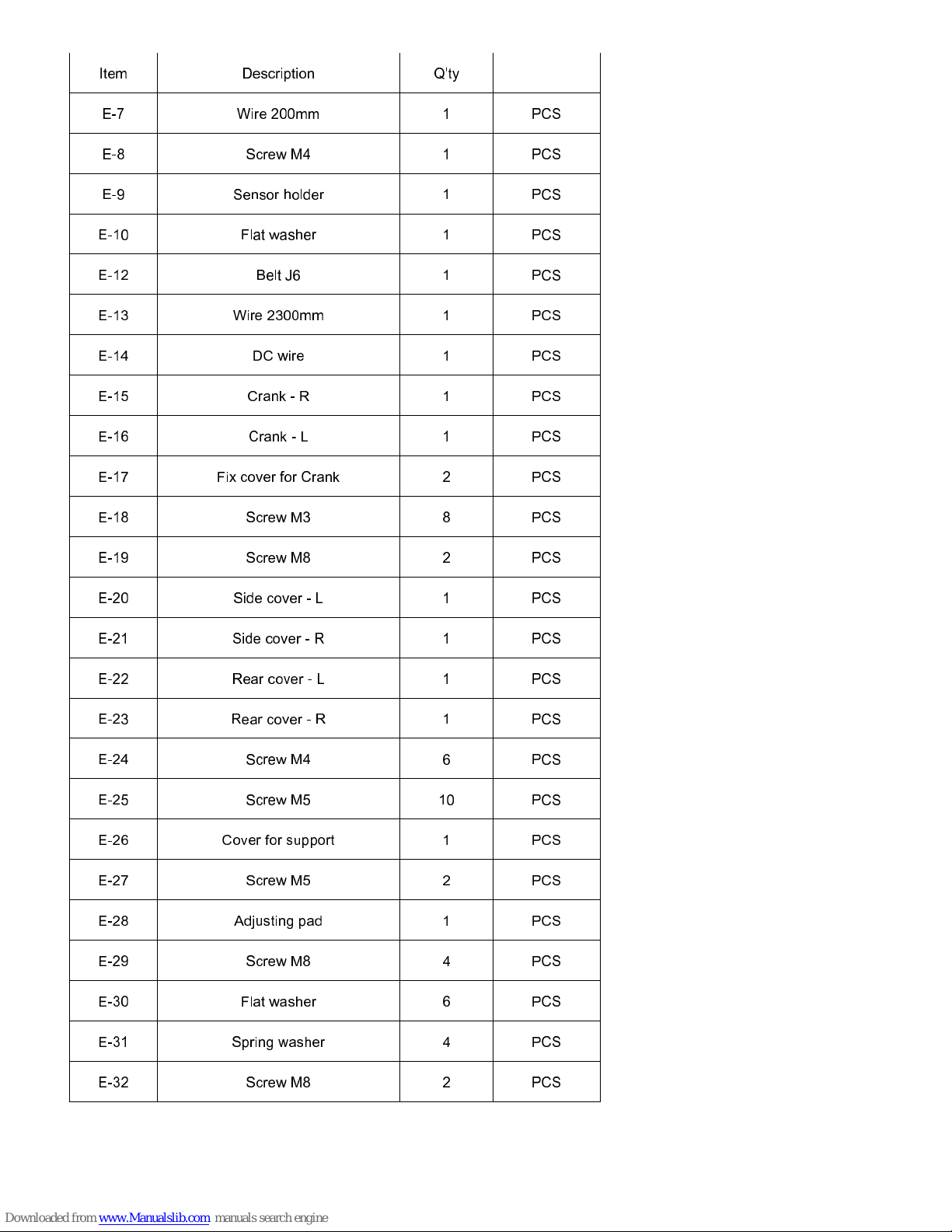
Item Description Q'ty
E-7 Wire 200mm 1 PCS
E-8 Screw M4 1 PCS
E-9 Sensor holder 1 PCS
E-10 Flat washer 1 PCS
E-12 Belt J6 1 PCS
E-13 Wire 2300mm 1 PCS
E-14 DC wire 1 PCS
E-15 Crank - R 1 PCS
E-16 Crank - L 1 PCS
E-17 Fix cover for Crank 2 PCS
E-18 Screw M3 8 PCS
E-19 Screw M8 2 PCS
E-20 Side cover - L 1 PCS
E-21 Side cover - R 1 PCS
E-22 Rear cover - L 1 PCS
E-23 Rear cover - R 1 PCS
E-24 Screw M4 6 PCS
E-25 Screw M5 10 PCS
E-26 Cover for support 1 PCS
E-27 Screw M5 2 PCS
E-28 Adjusting pad 1 PCS
E-29 Screw M8 4 PCS
E-30 Flat washer 6 PCS
E-31 Spring washer 4 PCS
E-32 Screw M8 2 PCS
5
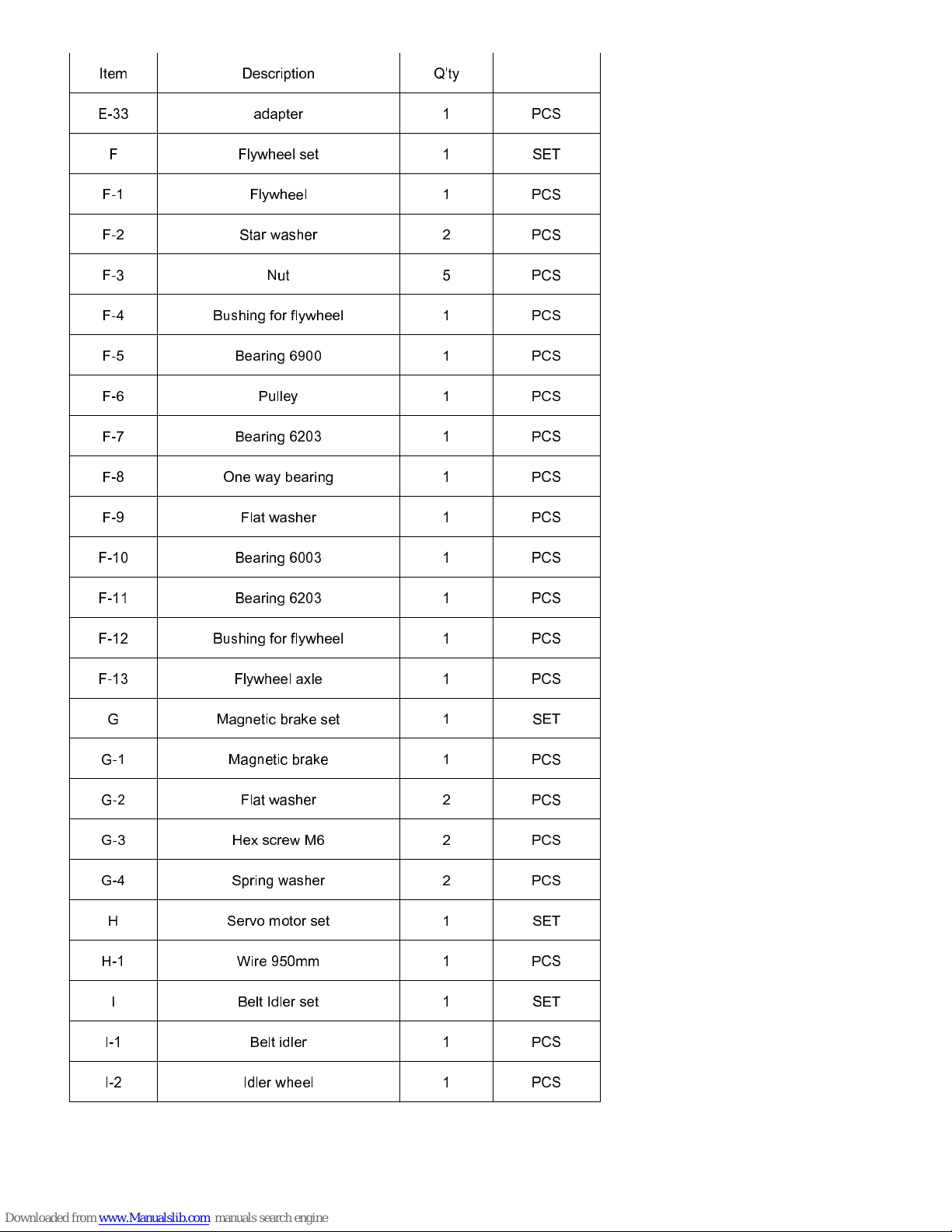
Item Description Q'ty
E-33 adapter 1 PCS
F Flywheel set 1 SET
F-1 Flywheel 1 PCS
F-2 Star washer 2 PCS
F-3 Nut 5 PCS
F-4 Bushing for flywheel 1 PCS
F-5 Bearing 6900 1 PCS
F-6 Pulley 1 PCS
F-7 Bearing 6203 1 PCS
F-8 One way bearing 1 PCS
F-9 Flat washer 1 PCS
F-10 Bearing 6003 1 PCS
F-11 Bearing 6203 1 PCS
F-12 Bushing for flywheel 1 PCS
F-13 Flywheel axle 1 PCS
G Magnetic brake set 1 SET
G-1 Magnetic brake 1 PCS
G-2 Flat washer 2 PCS
G-3 Hex screw M6 2 PCS
G-4 Spring washer 2 PCS
H Servo motor set 1 SET
H-1 Wire 950mm 1 PCS
I Belt Idler set 1 SET
I-1 Belt idler 1 PCS
I-2 Idler wheel 1 PCS
6
Item Description Q'ty
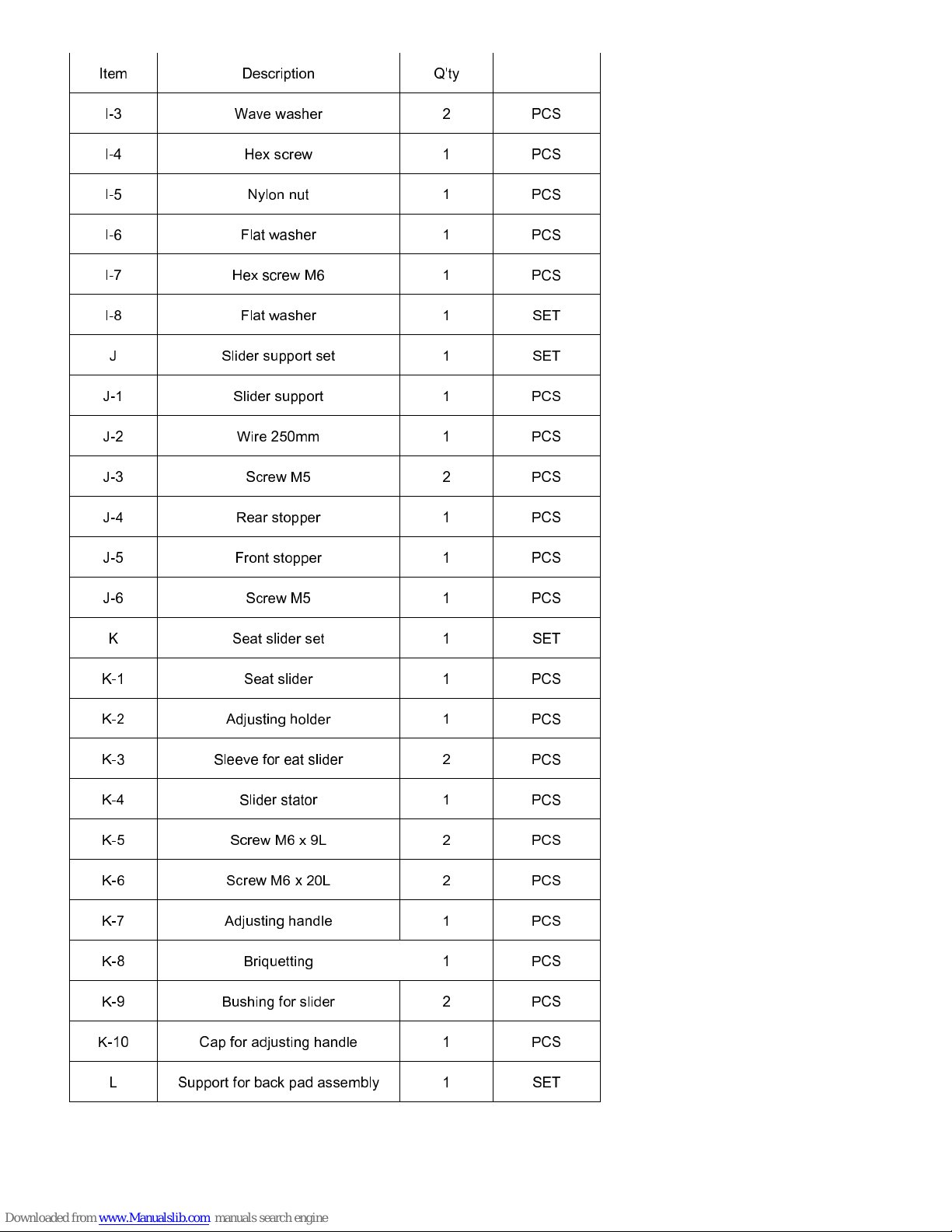
I-3 Wave washer 2 PCS
I-4 Hex screw 1 PCS
I-5 Nylon nut 1 PCS
I-6 Flat washer 1 PCS
I-7 Hex screw M6 1 PCS
I-8 Flat washer 1 SET
J Slider support set 1 SET
J-1 Slider support 1 PCS
J-2 Wire 250mm 1 PCS
J-3 Screw M5 2 PCS
J-4 Rear stopper 1 PCS
J-5 Front stopper 1 PCS
J-6 Screw M5 1 PCS
K Seat slider set 1 SET
K-1 Seat slider 1 PCS
K-2 Adjusting holder 1 PCS
K-3 Sleeve for eat slider 2 PCS
K-4 Slider stator 1 PCS
K-5 Screw M6 x 9L 2 PCS
K-6 Screw M6 x 20L 2 PCS
K-7 Adjusting handle 1 PCS
K-8 Briquetting 1 PCS
K-9 Bushing for slider 2 PCS
K-10 Cap for adjusting handle 1 PCS
L Support for back pad assembly 1 SET
 Loading...