

Orbit OBEI50A Owner's Manual
Owner’s Manual
A

Table of Contents
Product Safety …………………………………………….. 01.
Part Drawing & Contents ……………………...………….. 02.
Hardware & Tools ………………………………………….. 03.
Assembly …………………………………….…………….. 04.
Adjustment …………………………………….…………….. 10.
Trouble Shooting & Maintenance ……………..………… 11.
Computer ………………………………….……..………… A.
Warm Up ……………………………………..……………. B.
Part List ……………………………………..…………….. C.
Exploded View ……………………………………………. #.
FE150A18-20150422.1

1
Product Safety
Basic precautions should always be followed, including the following safety instructions when using this
equipment: Read all instructions before using this equipment.
1. Read all the instructions in this manual and do warm up exercises before using this equipment.
2. Before exercise, in order to avoid injuring your muscles, warm-up exercise for every muscle group is highly
recommended. Please refer to the Warm Up pages for pre and post workout.
3. Please make sure all components are not damaged and in working order before use. This equipment should be
placed on a flat surface while in use. Using a mat or other material on the ground is recommended.
4. Please wear proper clothes and shoes when using this equipment; do not wear clothes that might catch in any
part of the equipment.
5. Do not attempt any maintenance or adjustments other than those described in this manual. Should any problems
arise, discontinue use and consult an Authorized Service Representative.
6. Be careful when stepping on or leaving the pedals. Always hold the handlebars first and make sure the pedal at
your side is at its lowest position. Step on the pedal, and stride over the main frame then step on the other pedal.
When using, please hold onto the handlebars. To ensure the pedals run smoothly push or pull on the handlebars
first, then follow with leg motion. When stepping off the machine, make sure one pedal is at its lowest position
and step out of there before stepping out of the pedal at the highest position.
7. Do not use the equipment outdoors.
8. This equipment is for household use only.
9. Only one person should be on the equipment while in use.
10. Keep children and pets away from the product while in use. This machine is designed for adults only. If you feel
any chest pains, nausea, dizziness, or short of breath, you should stop exercising immediately and consult your
physician before continuing.
11. If you feel any chest pains, nausea, dizziness, or short of breath, you should stop exercising immediately and
consult your physician before continuing.
12. The maximum weight capacity for this product is 275 lbs / 125 kgs.
WARNING: Before beginning any exercise program consult your physician. This is especially important for the
persons who are over 35 years old or who have pre-existing health problems. Read all instructions
before using any fitness equipment.
CAUTION: Read all instructions carefully before operating this product. Retain this Owner’s Manual for future
reference.
2
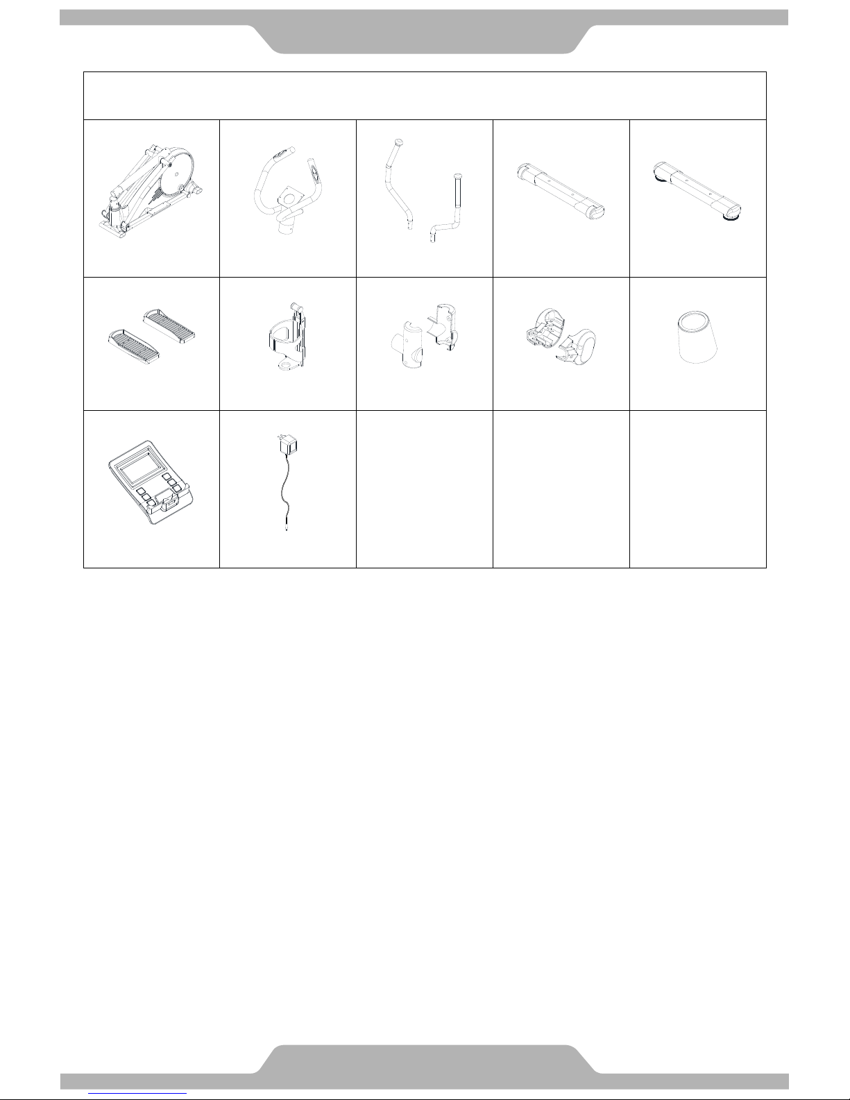
Part Drawing & Contents
Box Contents
A01 1Set
A09 1Set
A12/A13 2Set
A07 1Set
A08 1Set
Main Frame
Stationary Handlebar
Left/Right
Dual Action Handlebar
Front Stabilizer Tube
Rear Stabilizer Tube
C12/C30 2PC
C24 1PC
C29/C31 2Set
C03/C18 2Set
C06/C27 1Set
Foot Pedal
Water Bottle Holder
Dual Action Arm
Decorative Cover –A/B
Foot Tube Pivot
Decorative Cover –A/B
Hat Cover
Rubber Gasket
D02 1PC
D08 1PC
Computer
AC Adapter
3
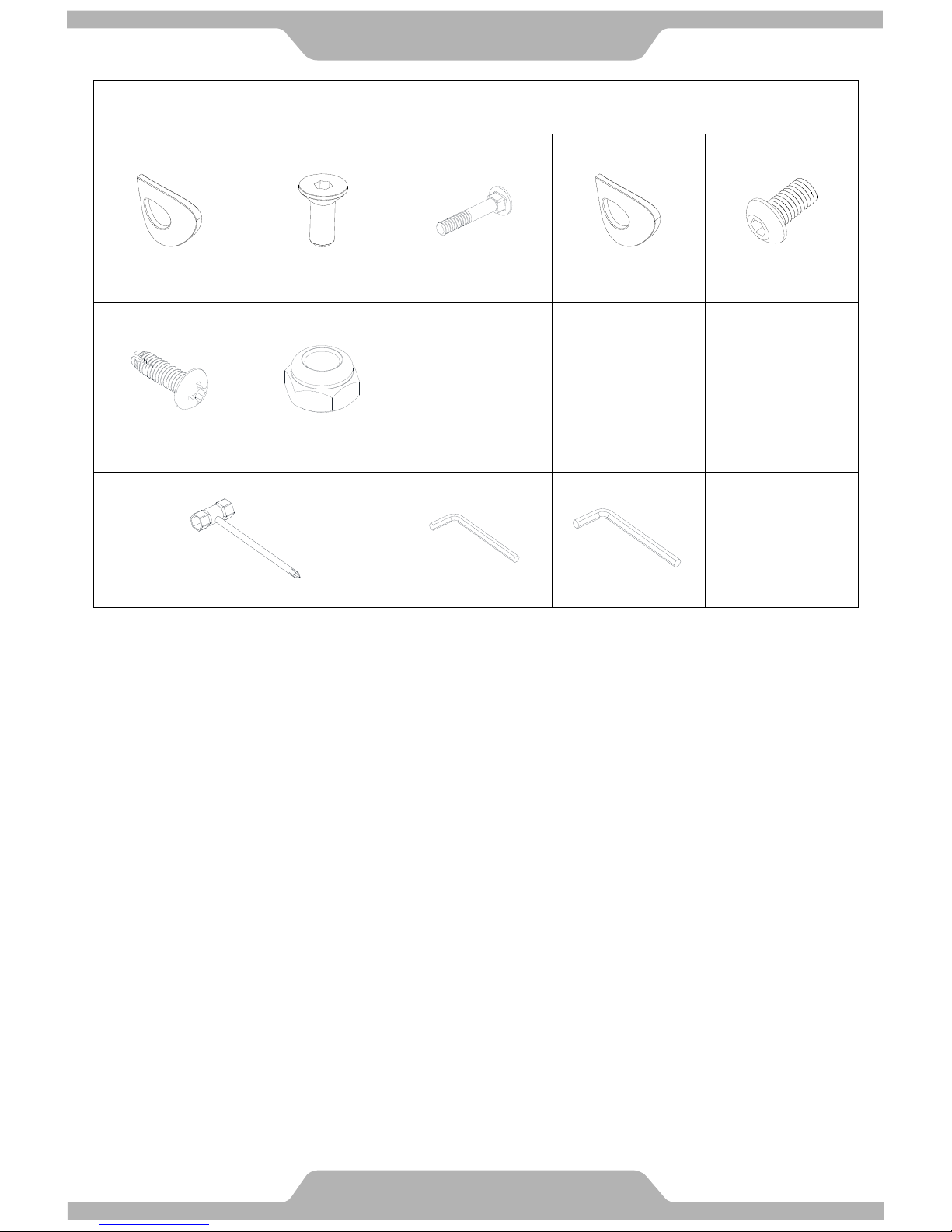
Hardware & Tools
Pack Contents
B01 (1) 6PC
B05 (2) 8PC
B04 (3) 4PC
B12 (4) 4PC
B02 (5) 6PC
Curve Washer
M8
Bolt
M6
Carriage Bolt
M8
Curve Washer
M8
Bolt
M8
B19 (6) 18PC
B09 (7) 4PC
Screw
M5
Nut
M8
(10) 1PC
(8) 1PC
(9) 1PC
Hex Tool with Phillips Screwdriver (13mm/14mm)
Allen Key (M4)
Allen Key (M5)
4
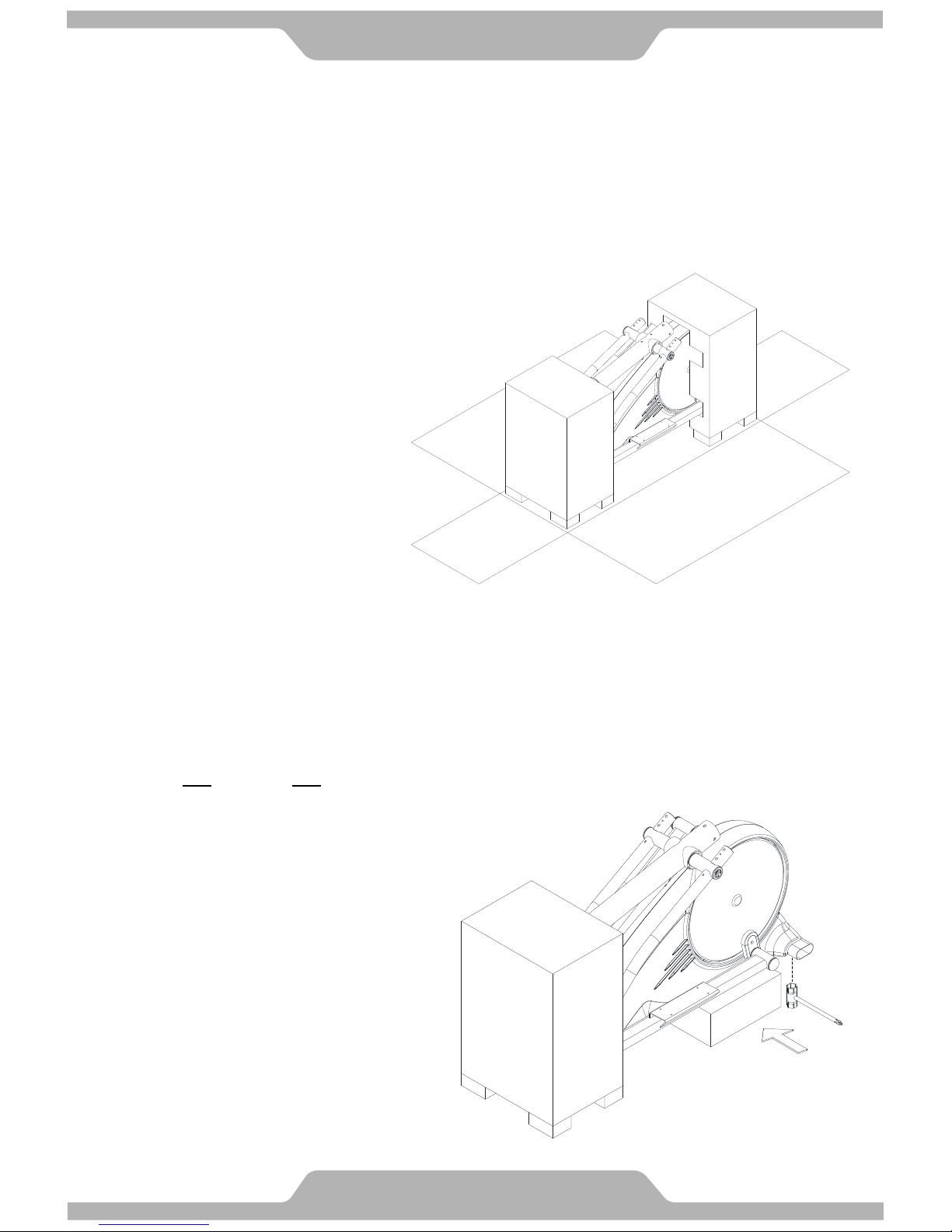
Assembly
1. Preparation
1.1 Clear a 2 meters time 2.5 meters working space before unpacking your Elliptical Cross Trainer.
1.2 The assembly steps required two persons.
2. Open carton
2.1 Use a sharp knife, open the carton and lay it flat on the floor.
2.2 Remove all loose components.
2.3 Refer to the checklist and check that everything is present.
NOTE:
To protect the Elliptical Cross Trainer while assembling we suggest that you do not remove the protective
packing material until it is absolutely necessary.
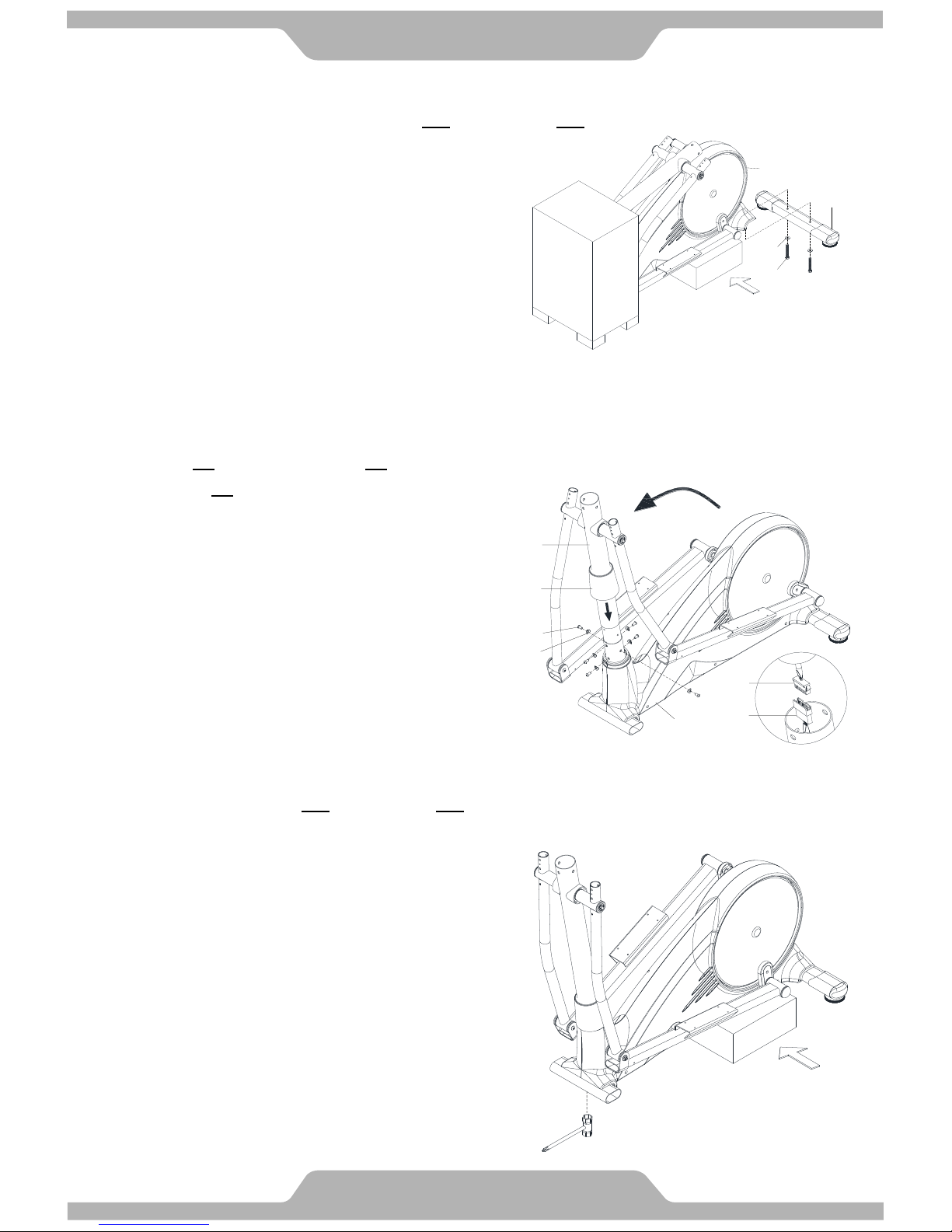
3. Remove Rear Protection Tube
3.1 Lift the rear of the machine off the floor and slide a polystyrene block under the rear of the machine.
3.2 Remove Two Bolts [B11], Two Washers [B10] and remove the Protection Tube.
[Remove bolts with the Hex Tool with Phillips Screw Driver provided.]
5
Assembly
4. Rear Stabilizer Tube Installation
4.1 Assemble the Rear Stabilizer Tube [A08] with Two Bolts [B11] and Two Washers [B10] which were removed from
step 3.2 and tighten firmly.
[Tighten bolts with the Hex Tool with Phillips Screw Driver provided.]
5. Upright Support Tube Installation
5.1 Lift the Upright Support Tube [A02] until it is vertical while the other person connects the matching connectors of
cable [D04/D05] as shown in the illustration below.
5.2 Then slide the Upright Support Tube [A02] into the hole of Main Frame [A01].
5.3 Assemble Six Blots [B02] by fingers, Six Curve Washers [B01] into Main Frame [A01]. Align all bolts slightly then
firmly tighten Six Bolts [B02].
5.4 Slide down the Hat Cover [C06] and push firmly.
[Tighten bolts with the M5 Allen Key provided.]
Attention: Cables can't be folded.
6. Remove Front Protection Tube
6.1 Remove the front polystyrene and place it under the front of the machine to lift it off the floor.
6.2 Refer the step 3 to remove Two Bolts [B11] and Two Washers [B10] from the front of machine and remove front
protection tube.
[Remove bolts with the Hex Tool with Phillips Screwdriver provided.]
D04
D05
C06
A01
A02
B02
B01
A08
B10
B11
A01
6
Assembly
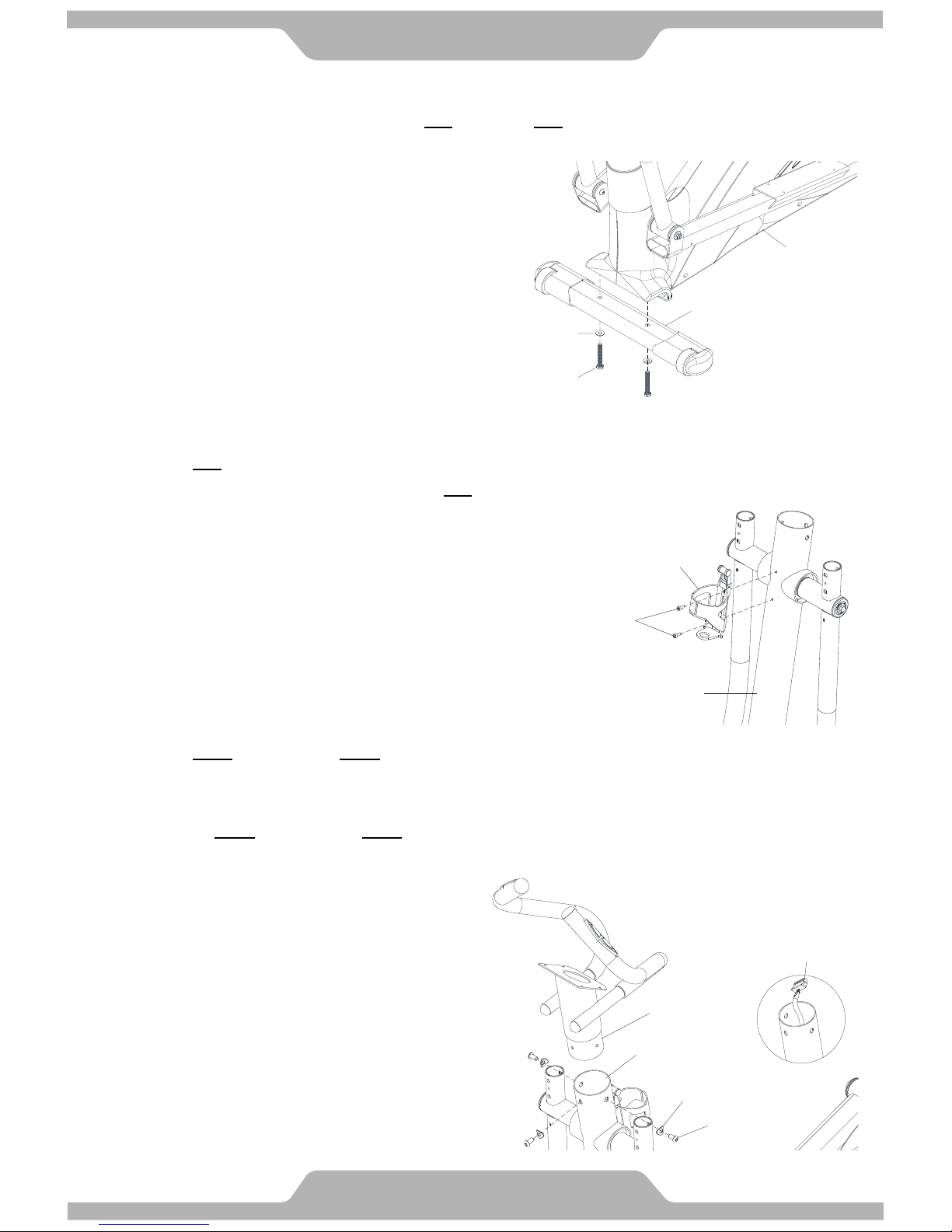
7. Front Stabilizer Tube Installation
7.1 Assemble the Front Stabilizer Tube [A07] with Two Bolts [B11], Two Washers [B10] which were removed from the
step 6.2 and tighten firmly.
7.2 Remove the polystyrene block and discard.
[Tighten bolts with the Hex Tool with Phillips Screwdriver provided.]
8. Water Bottle Holder Installation
8.1 Remove Two Screws [B16] from Upright Support Tube [A02].
8.2 Align Water Bottle Holder [C24] and fasten with Two Screws [B16] which were removed from step 8.1.
[Remove/Tighten screws with the M4 Allen Key provided.]
9. Stationary Handlebar Installation
9.1 Remove Three Bolts [B23] and Three Curve Washers [B01] from Stationary Handlebar [A09].
9.2 Route Cable [D04] through the bottom of Stationary Handlebar [A09] out the top of Stationary Handlebar [A09],
then slide the Stationary Handlebar [A09] into the opening hole of Upright Support Tube [A02].
9.3 Secure with Three Bolts [B23] and Three Curve Washers [B01] which were removed from step 9.1.
Before tightening make sure the Stationary Handlebar [A09] correctly positioned.
[Remove/Tighten bolts with the M5 Allen Key provided.]
Attention: Cables can't be folded.
B10
B11
A07
A01
A02
C24
B16
A09
B23
B01
D04
A02
 Loading...