

Orbit OBE8731B Owner's Manual

OBE8731B
OBE8731B

Before You Start
Thank you for purchasing this Product! For your safety and benefit, read this manual carefully before using
the machine.
Prior to assembly, remove comp onents from the box and verify t hat all the listed parts were supplied.
Assembly instructions are described in the following steps and illustr ations.
IMPORTANT SAFETY NOTICE
PRECAUTIONS
BE SURE TO READ THE ENTIRE MANUAL BEFORE YOU ASSEMBLE OR OPERATE YOUR
MACHINE. IN PARTICULAR, NOTE THE FOLLOWING SAFETY PRECAUTIONS:
01- Check all the screws, nuts and other connections before using the machine for the first time and ensure
that the trainer is in the safe condition.
02- Set up the machine in a dry level place and leave it away from moisture and water.
03- Place a suitable base (e.g. rubber mat, wooden board etc.) beneath the machine in the area of assembly
to avoid dirt and etc..
04- Before beginning training, remove all objects within a radius of 2 meters from the machine.
05- DO NOT use aggressive cleaning articles to clean the machine, Only use the supplied tools or suitable
tools of your own to assemble the machine or repair any parts of machine. Remove drops of sweat from
the machine immediately after finishing training.
06- Your health can be affected by incorrect or excessive training. Consult a doctor before beginning a training
program. He can define the maximum setting (Pulse. Watts. Duration of training etc) to which you may
train yourself and can get precise information during training. This machine is not suitable for therapeutic
purpose.
07- Only do training on the machine when it is in correct working way. Use only original spare parts for any
necessary repairs.
08- This machine can be used for only one person’s training at a time.
09- Wear training clothes and shoes which are suitable for fitness training with the machine. Your training
shoes should be appropriate for the trainer.
10- If you have a feeling of dizziness, sickness or other abnormal symptoms, please stop training and consult
a doctor asap.
11- People such as children and handicapped persons should only use the machine in the presence of
another person who can give aid and advice.
12- The power of the machine increases with increasing the speed, and the reverse.
13- To reduce the risk of electrical shock, burns, fire or other possible injuries to the user, it is important to
review this manual and the precautions before operation.
WARNING: BEFORE BEGINNING ANY EXERCISE PROGRAM, CONSULT YOUR PHYSICIAN.
THIS IS ESPECIALLY IMPORTANT FOR INDIVIDUALS OVER TH E AGE OF 35 OR PERSONS WITH
PRE-EXISTING HEALTH PROBLEMS. READ ALL INSTRUCTIONS BEFORE USING ANY FITNESS
EQUIPMENT.
SAVE THESE INSTRUCTIONS / Maximum user’s weight: 130KGS
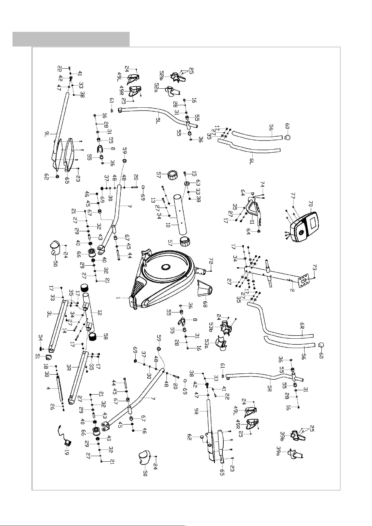
EXPLODED DIAGRAM

PARTS LIST
Part
No.
Description
Qty
Part
No.
Description
Qty
1
Main frame
1
38
Nylon nut M8
4
2
Handlebar post
1
39a/b
Right swing tube cover
1/1
3L/R
Guide rail
1/1
40
Bearing 6003Z
4
4
Rear supporting tube
1
41
Bushing
2
5L/R
Swing bar
1/1
42
Universal joint
2
6L/R
Handlebar
1/1
43
Short axle
2
7
Roller bracket
2
44
Hex bolt M12x125
2
8
Connecting joint
2
45
Flat washerφ12*φ24*2
4
9L/R
Pedal bar
1/1
46
Nylon nut M12
2
10
Front bottom tube
1
47
Hex nut M12
2
11
Handrail
1
48
Bushing
4
12
Rear bottom tube
1
49L/R
Pedal bar cover
2/2
13
Inner hex screw M8 XL93
2
50
Roller cover
2
14
Inner hex screw M8 XL75
2
51
End cap
2
15
Hex bolt M8×38×L12
2
52a/b
Left swing tube cover
1/1
16
Hex bolt M8X20
4
53a/b
Handlebar cover
1/1
17
Hex bolt M8X16
22
54
Adjustable pad
2
18
Hex bolt M10X20
2
55
Axle bushing
8
19
Adaptor
1
56
Foam grip
2
20
Bolt M10×65×L20
2
57
End cap
2
21
Bolt M8*16
4
58
Oval cap
2
22
Bolt M8*30
2
59
Axle bushing
2
23
Cross taping screw M6×15
8
60
Round end cap
2
24
Cross taping screw ST4.2*18
8
61
Round end cap φ32*2
2
25
Cross taping screw ST4.2*12
6
62
Round end cap φ28*1.5
2
26
Spring washer D10
2
63
Roller
2
27
Spring washer D8
22
64
Round end cap
2
28
Spring washer D8
4
65
Pedal
2
29
Flat washerφ17*φ22*2
4
66
Roller of guide rail
2
30
Flat washer D10*D20*2
4
67
Axle bushing
4
31
Flat washer D8 XD32 X2
4
68
Front cover
1
32
Flat washer D8 XD20X2
4
69
End cap S17
4
33
Flat washer D8 XD16 X1.5
8
70
Computer
1
34
Arch washerφ8*1.5*φ25
12
71
Screw M4*10
4
35
Arch washerφ8*1.5*φ20
10
72
Sensor wire
1
36
Wave washer D21
4
73
Extension wire
1
37
Nylon nut M10
2
74
Pulse wire
2
NOTE:
Most of the listed assembly hardware has been packaged separately, but some hardware
items have been preinstalled in the identified assembly parts. In these instances, simply remove
and reinstall the hardware as assembly is required.
Please reference the individual assembly steps and make note of all preinstalled hardware.

♦ Take time to review the manual and familiarize yourself with the entire assembly process
before proceeding.
♦ Although this product can be assembled by one person, we recommend having the
assistance of another individual. This is especially convenient when assembling multiple parts or
moving the equipment.
Assembly Tip: It is always helpful to pre-stage the items needed for each assembly step.
ASSEMBLY INSTRUCTIONS
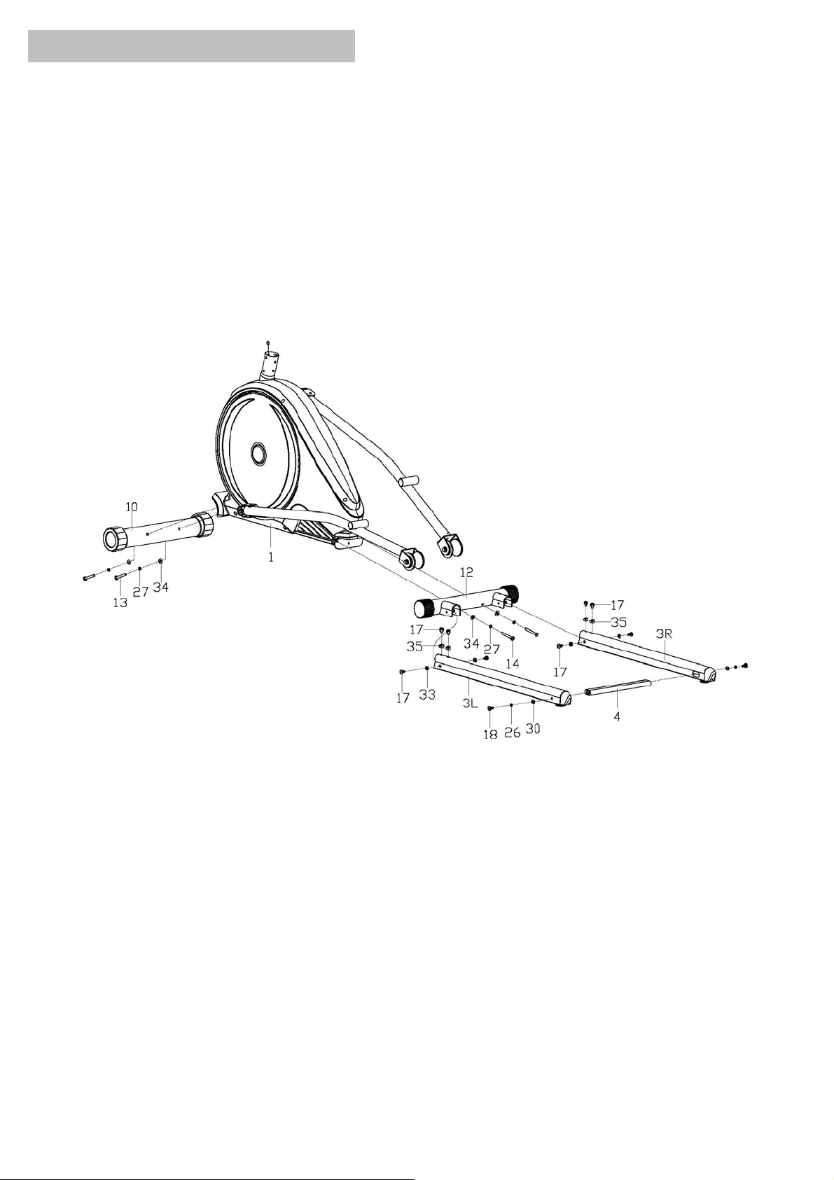
Step 1:
A: Lock the Front Bottom Tube (10) into the Main Frame (1) with Inner Hex Screw (13), Spring Washer
(27), and Arch Washer (34).
B: Lock the Rear Bottom Tube (12) into the Main Frame (1) with Inner Hex Screw (14), Spring Washer
(27), and Arch Washer (34).
C: Insert the Rear Supporting Tube (4) into the Guide Rail (3L/R), and lock it with Hex Bolt (18), Spring
Washer (26), and Flat Washer (30).
D: Lock the Guide Rail (3L/R) into the Rear Bottom Tube (12) with Hex Bolt (17), Spring Washer (35),
and Flat Washer (33).
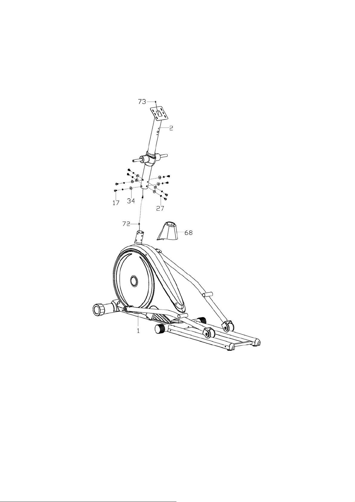
Step 2:
A: Insert the Front Cover (68) to the Handlebar Post (2), then connect the Sensor Wire (72), and
Extension Wire (73).
B: Insert the Handlebar Post (2) into the Main Frame (1) and lock it tightly with Hex Bolt (17), Spring
Washer (27), and Arch Washer (34).
 Loading...