

Orbit OBE165AF Owner's Manual
OBE165AF
Elliptical Cross Trainer

TABLE OF CONTENTS
FE165AFQ-20151007.r1
PRODUCT SAFETY …………………………………………….. 01.
PART DRAWING & CONTENTS ………………...…………….. 02.
HARDWARE & TOOLS ………………………………………….. 04.
ASSEMBLY ……………………………………………………….. 05.
FOLDING ……………………………………………………….. 11.
ADJUSTMENT …………………………………………………….. 12.
TROUBLE SHOOTING & MAINTENANCE …………………… 13.
COMPUTER ……………………………….…………………… A.
WARM UP ………………………………………….……………. B.
PART LIST ……………………………………………………….. C.
EXPLODED VIEW ………………………………………………. #.

1
PRODUCT SAFETY
BASIC PRECAUTIONS SHOULD ALWAYS BE FOLLOWED, INCLUDING THE FOLLOWING SAFETY INSTRUCTIONS WHEN
USING THIS EQUIPMENT: READ ALL INSTRUCTIONS BEFORE USING THIS EQUIPMENT.
1. Read all the instructions in this manual and do warm up exercises before using this equipment.
2. Before exercise, in order to avoid injuring your muscles, warm-up exercise for every muscle group is highly
recommended. Please refer to the Warm Up pages for pre and post workout.
3. Please make sure all components are not damaged and in working order before use. This equipment should be
placed on a flat surface while in use. Using a mat or other material on the ground is recommended.
4. Please wear proper clothes and shoes when using this equipment; do not wear clothes that might catch in any
part of the equipment.
5. Do not attempt any maintenance or adjustments other than those described in this manual. Should any problems
arise, discontinue use and consult an Authorized Service Representative.
6. Be careful when stepping on or leaving the pedals. Always hold the handlebars first and make sure the pedal at
your side is at its lowest position. Step on the pedal, and stride over the main frame then step on the other pedal.
When using, please hold onto the handlebars. To ensure the pedals run smoothly push or pull on the handlebars
first, then follow with leg motion. When stepping off the machine, make sure one pedal is at its lowest position
and step out of there before stepping out of the pedal at the highest position.
7. Do not use the equipment outdoors.
8. This equipment is for household use only.
9. Only one person should be on the equipment while in use.
10. Keep children and pets away from the product while in use. This machine is designed for adults only. If you feel
any chest pains, nausea, dizziness, or short of breath, you should stop exercising immediately and consult your
physician before continuing.
11. If you feel any chest pains, nausea, dizziness, or short of breath, you should stop exercising immediately and
consult your physician before continuing.
12. The maximum weight capacity for this product is 300 lbs / 135 kgs.
WARNING: Before beginning any exercise program consult your physician. This is especially important for the
persons who are over 35 years old or who have pre-existing health problems. Read all instructions
before using any fitness equipment.
CAUTION: Read all instructions carefully before operating this product. Retain this Owner’s Manual for future
reference.
2
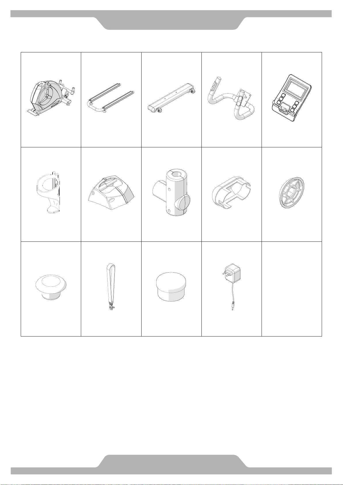
PART DRAWING & CONTENTS
BOX CONTENTS -A
A01 1SET
A12 1SET
A16 1SET
A15 1SET
D02 1PC
Main Frame
U Shape Rail
Front Stabilizer
Stationary Handlebar
Computer
C16 1PC
C07/ C08 1SET
C17/ C18 2SET
C04 2PC
C11 4PC
Water Bottle Holder
Upright Post Decorative
Cover /L & R
Handrail Arm Decorative
Cover -A/B
Oval End Cap
Nut Cap M8
C31 8PC
F02 2PC
1pc
D08 1PC
End Cap for Pedal
Ribbon & Hook
Lubricant
AC Adapter
3
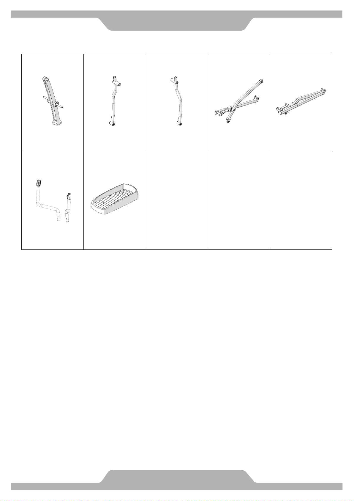
PART DRAWING & CONTENTS
BOX CONTENTS -B
A02 1SET
A03 1SET
A04 1SET
A05/ A07 1SET
A06/ A08 1SET
Upright Post
Handrail Arm /L
Handrail Arm /R
Foot Bar Set /L
Foot Bar Set /R
A13/ A14 2SET
C12 2PC
Handrail /L & R
Foot Pedal
4
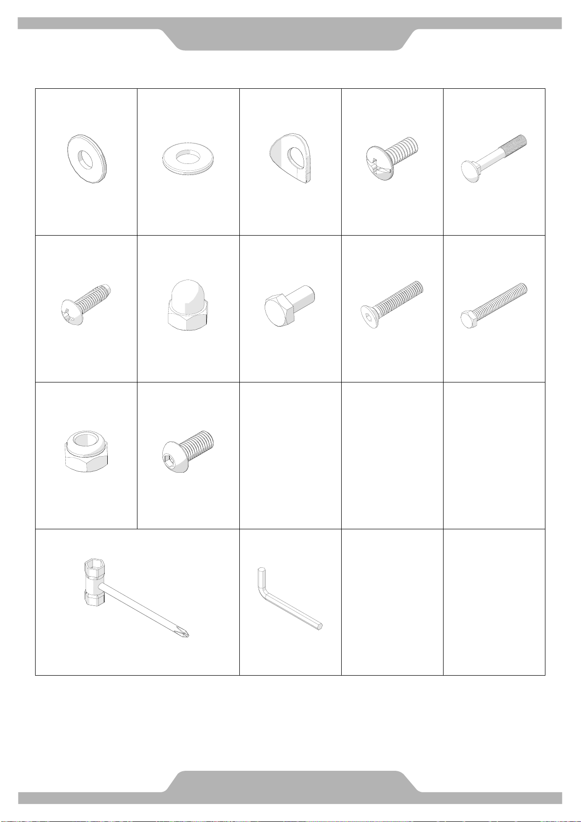
Hardware & Tools
PACK CONTENTS
B33 4PC
B42 4PC
B30 12PC
B23 8PC
B28 4PC
Washer
5/16''x20x2.0T
Washer
3/8"x20x2.0T
Curve Washer
M8x20x1.5T
Screw
M6x15
Carriage Bolt
M8x50
B21 10PC
B43 2PC
B32 4PC
B40 2PC
B41 2PC
Screw
M5x16
3/8" Dome Nut
Bolt
M8x16
Screw
M8x25
Bolt
3/8"x2-1/2”
B29 4PC
B13 8PC
Nylon Nut
M8
Bolt
M8x18
1PC
1PC
Hex Tool with Phillips Screwdriver (13mm/14mm)
Allen Key (M5)
5
ASSEMBLY
C04
A01
Tool
A01
B41
B42
B43
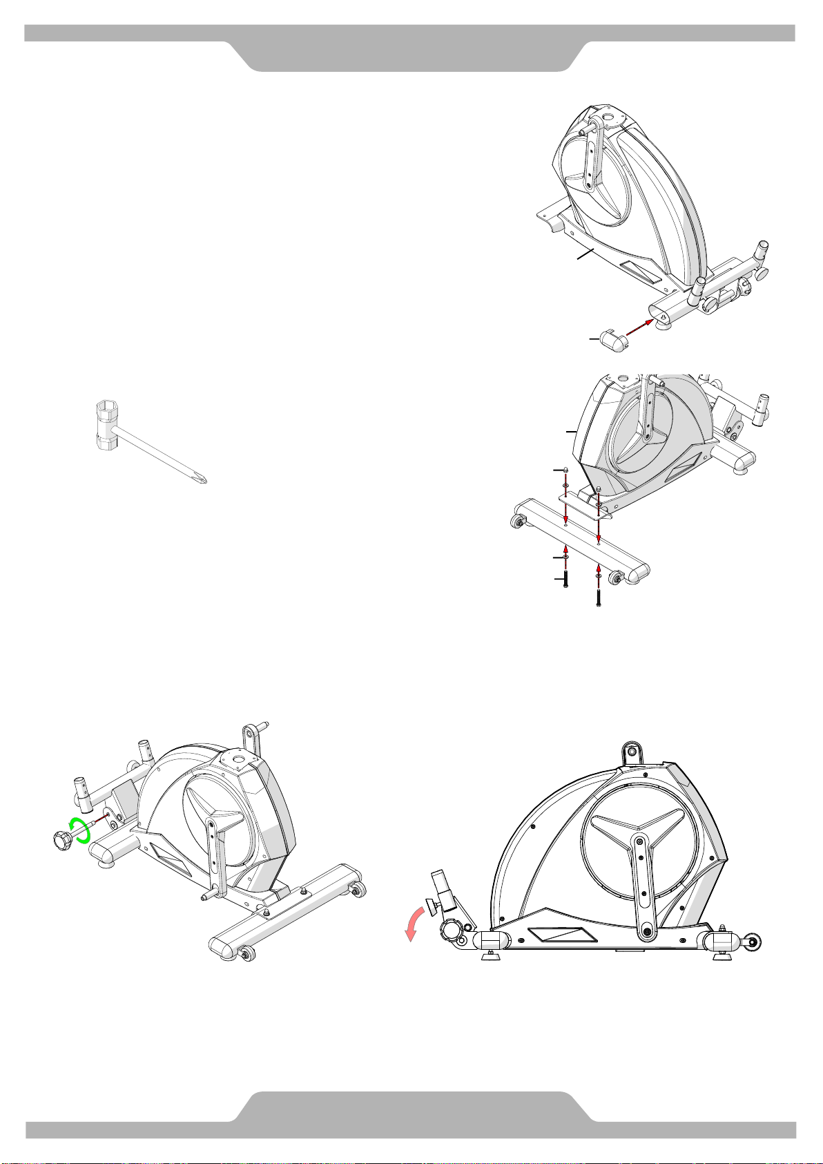
1. END CAPS INSTALLATION
1.1 Refer the right figure to assemble the end cap of other side.
2. FRONT STABILIZER TUBE INSTALLATION
3. ADJUST THE FOLDING MECHANISM OF MAIN FRAME.
6
ASSEMBLY
Lubricant
(Both Shaft)
Allen Key (M5)
B13
B30
A12
A17
Tool
B14
A02
A01
A02
A03
B32
B33
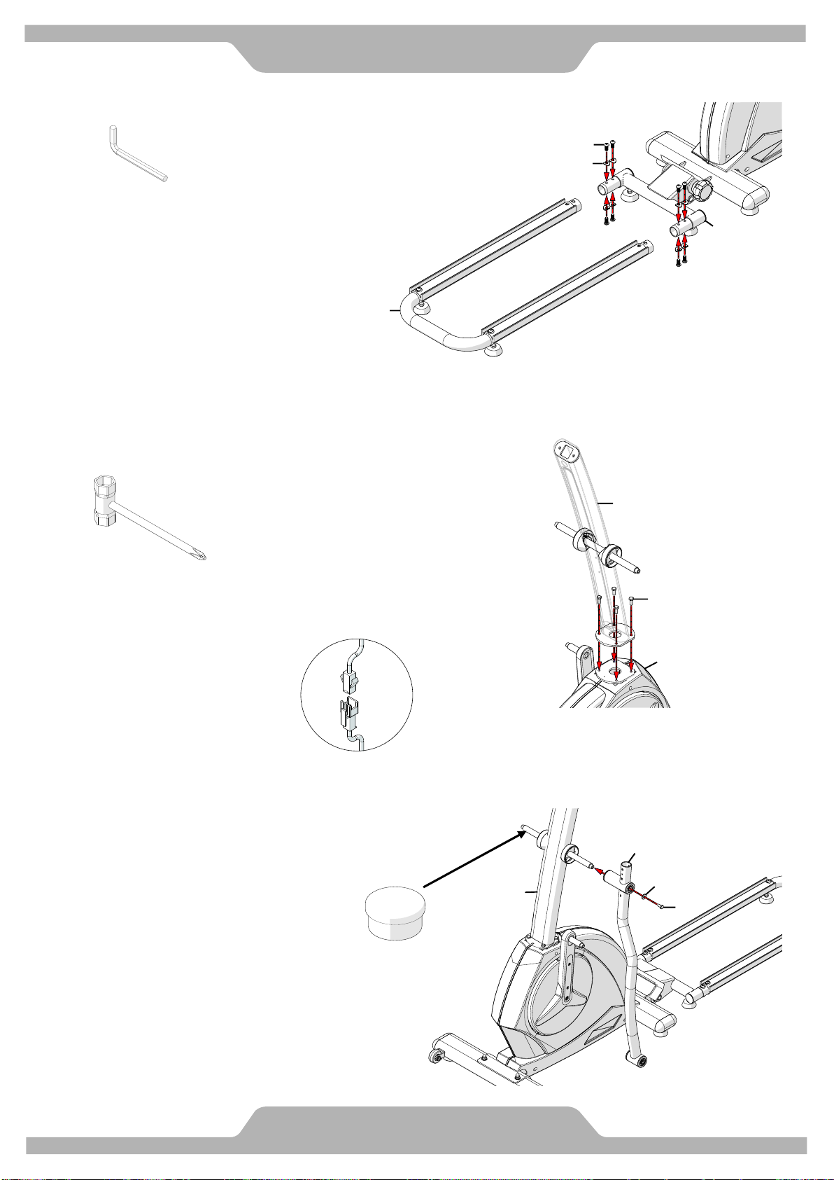
4. RAIL TUBE INSTALLATION
5. UPRIGHT POST INSTALLATION
5.1 Remove screws from the plate of Main Frame.
Attention: Cables can't be folded.
6. HANDRAIL ARMS INSTALLATION
6.1 Refer the right figure to assemble the Handrail Arm of other side.
7
ASSEMBLY
Tool
C11
B32
B33
A07
A11
A05
A03
C11
B29
B33
B24
Tool
A03
A13
B28
B29
B30
B40
A15
A02
Allen Key (M5)
Lubricant
(Both Shaft)
Allen Key (M5)
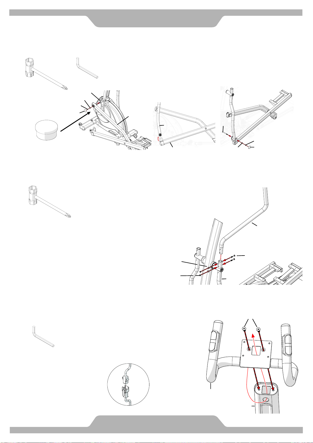
7. FOOT BAR SET INSTALLATION
7.1 Refer the below figures to assemble the Foot Bar Set of other side.
7.2 Remove screw, washer, nut and nut cap from Foot Pedal Tube. (mid-figure)
8. HANDRAILS INSTALLATION
8.1 Refer the right figure to assemble the Handrail of other side.
9. STATIONARY HANDLEBAR INSTALLATION
9.1 Route the cables from Stationary Handlebar through the round hole at Upright Post.
9.2 Route all cable from Upright Post through the Stationary Handlebar.
Attention: Cables can't be folded.
 Loading...