

Orbit OBA2123A Owner's Manual
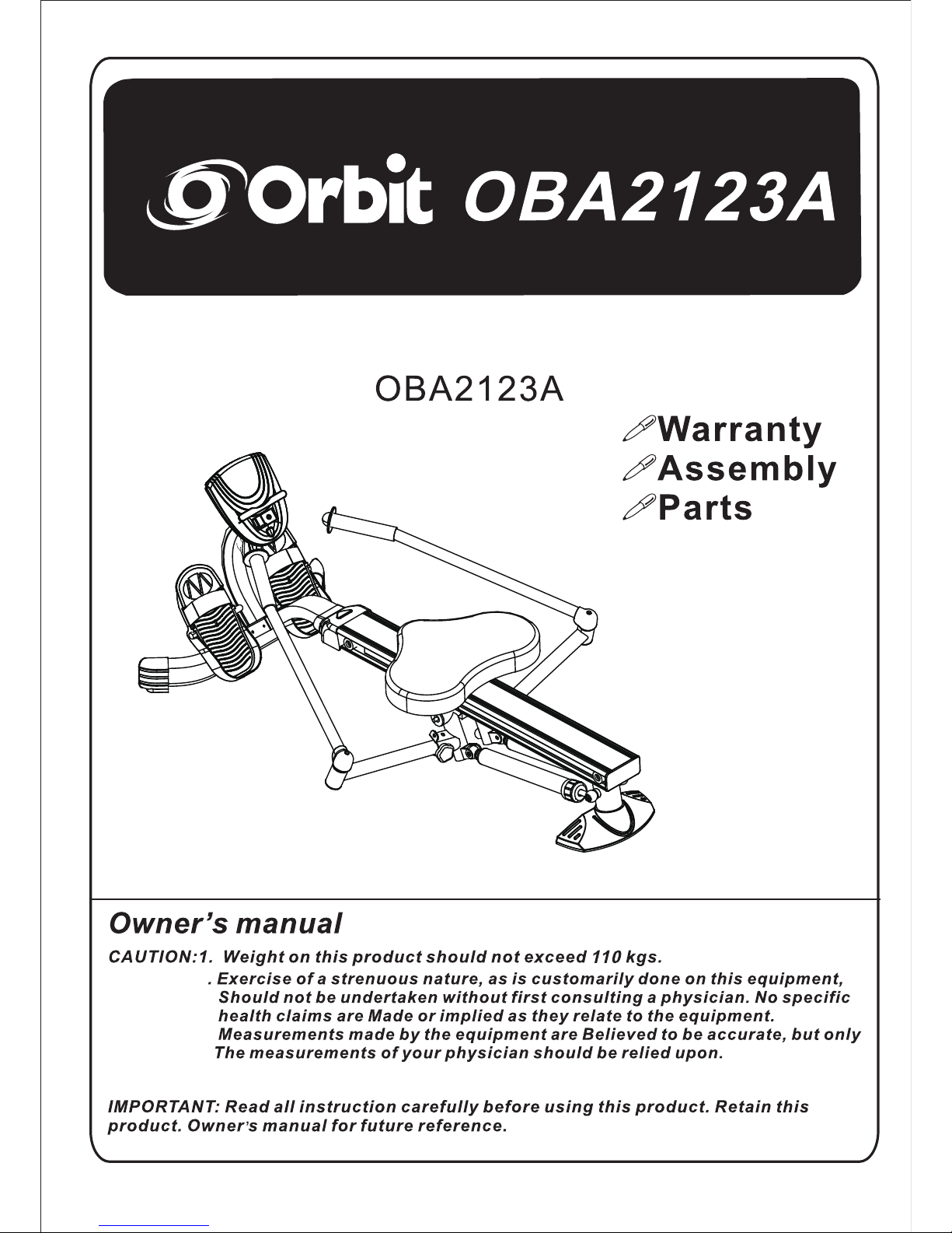
O BA2123A
2

TABLE OF CONTENTS
Safety Instructions ...................................... 2
Before You Begin ........................................
4
Equipment Warning, Caution & Notice Labels ... 5
Hardware Identication Chart .................... 6
Assembly Instructions ................................ 7
Operational Instructions ........................... 12
Maintenance ...............................................
13
Storage ....................................................... 14
Conditioning Guidelines ........................... 15
Warm-Up and Cool-Down ......................... 16
Warranty .....................................................
17
Product Parts Drawing .............................. 18
Parts List .................................................... 19
Notes ........................................................... 21
Fax/Mail Ordering Form ............................ 22
SAFETY INSTRUCTIONS
1
1.
S
ave these instructions and ensure that other exercisers read this manual prior to using the
product
for the first time.
2. Read all warnings and cautions posted on the product.
3. The product should only be used after a thorough review of the Owner’s Manual. Make sure
that it is properly assembled and tightened before use.
4. We recommend that two people be available for assembly of this product.
5. Keep children away from the product. Do not allow children to use or play on the product.
Keep children and pets away from the product when it is in use.
6. It is recommended that you place this exercise equipment on an equipment mat.
7. Set up and operate the product on a solid level surface. Do not position the product on
loose rugs or uneven surfaces.
8. Make sure that adequate space is available for access to and around the product.
9. Keep fingers clear of all pinch points when folding and unfolding the product.
10. Before using, inspect the product for worn or loose components, and securely tighten or replace
any worn or loose components prior to use.
11. Shocks on rowers get HOT during use. To avoid burns, do not touch the shock until it has time to
cool.
12. Consult a physician prior to commencing an exercise program and follow his/her
recommendations in developing your tness program. If at any time during exercise you feel faint,
dizzy, or experience pain, stop and consult your physician.
13. Always choose the workout which best ts your physical strength and exibility level. Know your
limits and train within them. Always use common sense when exercising.
14. Do not wear loose or dangling clothing while using the product.
15. Never exercise in bare feet or socks; always wear proper footwear such as running, walking, or
cross training shoes that t well, provide foot support, and feature non-skid rubber soles.
16. Be careful to maintain your balance while using, mounting, dismounting, or assembling the
product, loss of balance may result in a fall and serious bodily injury.
17.
Do not use the seat to move the product. The Seat will move and the Seat Carriage may pinch
your hand or fingers.
18.
The product should not be used by persons weighing over 250 pounds.
19.
The product should be used by only one person at a time.
20.
The product is for consumer use only. It is not for use in public or semipublic facilities.
!
WARNING
This product contains a chemical known to the State of California to cause
cancer and birth defects or other reproductive harm.
Consult your physician before starting this or any exercise program. This is
especially important if you are over the age of 35, have never exercised before,
are pregnant, or suffer from any health problem. This product is for home use
only. Do not use in institutional or commercial applications. Failure to follow
all warnings and instructions could result in serious injury or death.
To reduce the risk of serious injury, read the following Safety Instructions
before using the product.
!
WARNING
!
WARNING
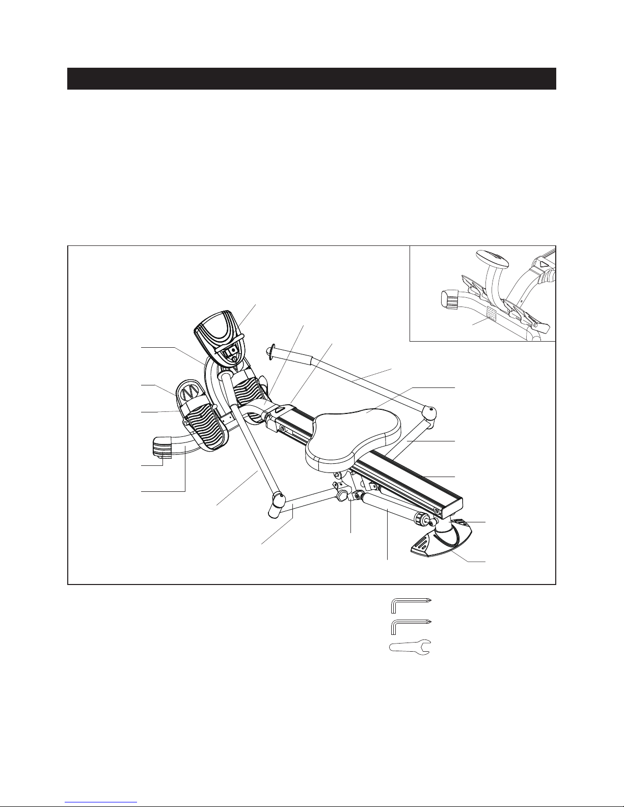
Bef ore reading f urt he r, pleas e rev i ew th e drawing below and familiarize yourself with the
parts that are labeled.
BEFORE YOU BEGIN
Be sure to have the name and model number of the product available when you contact us.
2
THE FOLLOWING TOOLS ARE REQUIRED FOR ASSEMBLY : Allen Wrench (5mm)
Allen Wrench (5mm)
Wrench (13mm)
Center Beam
Extension Arm
Extension Arm
Pivot Connector
Shock
Rear
Support
Stabilizer
Cap
Seat
Left Handlebar
Right Handlebar
Front Cover
Front Support
Meter
Meter Post
Pedal
Front
Stabilizer
Left
Stand Cap
Warning Label
Pedal Strap

Label is larger than actual size
This chart is provided to help identify the warning, caution, and notice labels on the product.
Please take a moment to familiarize yourself with all of the warning, caution, and notice labels.
EQUIPMENT WARNING, CAUTION & NOTICE LABELS
WARNING LABEL(67)W1
3
110kg
4
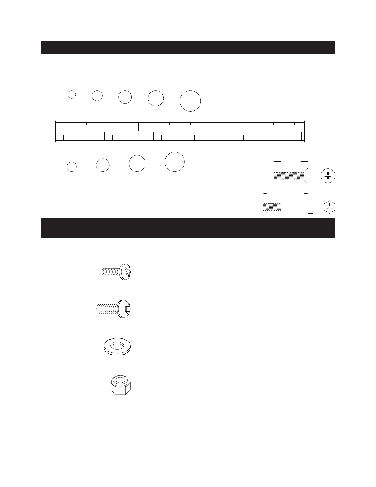
length
length
mm.
in.
INCHES
This chart is provided
to help identify the fasteners used in the assembly process. Place the washers or
the ends of the bolts or screws on the circles to check for the correct diameter. Use the small scale to
check the length of the bolts and screws.
NOTICE: The length of all bolts and screws, except those with flat
heads, is measured from below the head to the end of the bolt
or screw. Flat head bolts and screws are measured from the
top of the head to the end of the bolt or screw.
After unpacking
the unit, open the hardware bag and make sure that you have all the following
fasteners. Some fasteners may be already attached to the parts.
MILLIMETERS
0 10 20 30
40 50 60 70 80 90
100 110 120 130 140
150
0 1/2
1 1/2 2 1/2 3 1/2
4 1/2 5 1/2 6
6 8
10 12
3/16"
1/4" 5/16" 3/8" 1/2
"
HARDWARE IDE N TIFICA
TION CHART
Part No. and Description Qty
17
Large W
asher (M8) 2
9
W
asher (M8) 8
8 Bolt, Button Head (M8 x 1.25 x 15mm) 8
13 Bolt, Button Head (M8 x 1.25 x 25mm) 2
10 Screw, Round Head (M5 x 0.8 x 12mm) 2
14 Nylon Nut (M8 x 1.25) 2
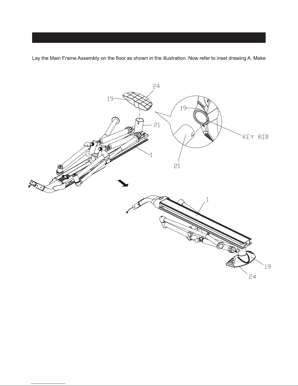
ASSEMBLY INSTRUCTIONS
STEP 1
sure the Key Rib
in the STABILIZER CAP(5) aligns with the slot in the REAR SUPPORT(21), then press the
STABILIZER CAP(5) onto the REAR SUPPORT(4). Turn the Main Frame Assembly to the normal upright
position and make sure the STABILIZER PAD(24) is secured to the STABILIZER CAP(19).
5
 Loading...