

Page 1

OWNER’S MANUAL
CAUTION: Exercise of a strenuous nature as is customarily done on this equipment, should not be undertaken without rst
consulting a physician before beginning any exercise program.
No specic health claims are made or implied as they relate to the equipment.
IMPORTANT: Read all assembly instructions and safety precautions carefully in the Owners manual before using this product.
Reference all safety guidelines and warning labels. Retain this products Owners Manual for future references.
SAFETY: Always warm up your muscles before starting a workout. Stretching should be performed in both the warm
up and cool down phases of a training program. Should you feel dizziness at any time while exercising, stop
immediately and consult your physician.
• Warranty
• Assembly
• Parts
TOOLS REQUIRED
FOR ASSEMBLY
- Adjustable Wrench
- Pliers
- Hammer
Page 2

1
Catalogue
Catalogue------------------------------------------------------------------ 1
Warning-------------------------------------------------------------------- 1
Assembling steps -----------------------------------------------------2-15
Exploded view ------------------------------------------------------16-17
Parts list --------------------------------------------------------------18-22
Daily Maintenance------------------------------------------------------22
Warning
1. Before exercise, please check to make sure all bolts are tightened and handlebar welds are
intact.
2. Wear appropriate footwear during work out. Do not flip the handlebars during exercise.
3. When weight stack, suspender or other parts are caught, ask another person’s help to avoid the
sudden drop of weight stack.
4. Do not distort the cable when you adjust its length (tightness). After using for a period of time,
you should check if cable skin has worn out or the cable is badly stretched, contact the
serviceman to repair or replace as soon as you find problems.
5. Do not drop weight stacks all of a sudden to avoid damage and injury. You should always lower
the weight stacks slowly.
6. Do not insert hand and other parts of the body between/under weight stacks and other moving
parts to avoid injury.
7. Children under 16 should exercise under adult’s guidance.
8. People have special conditions (for example, aged or diseased) should always consult your
physician before starting exercise.
Page 3
2
Assembling steps
1. Remove all parts out of boxes and place around area of installation! Place bolt packs in front of
the area where you want the gym.
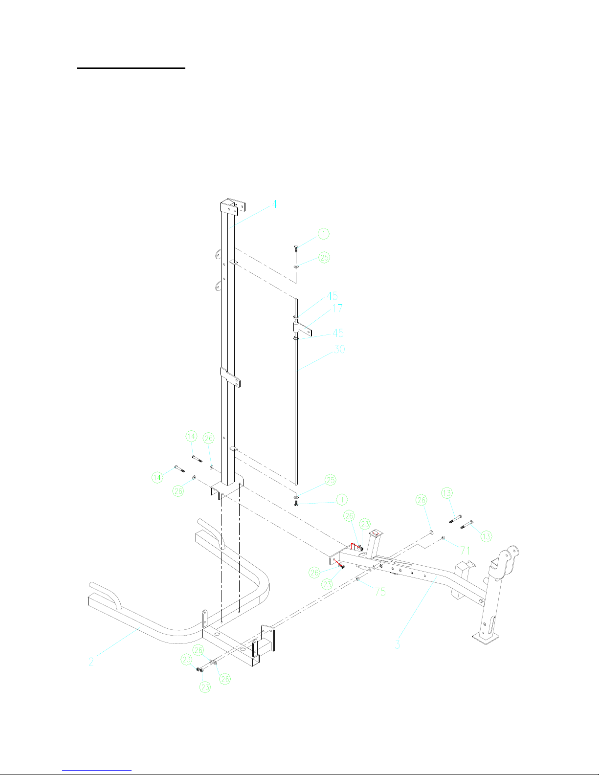
2. Place part (2) in desired position, then connect part (3) with part (4) using bolts
(M10x75mm)(13), bolts (M10x80mm)(14), washers (26) and locknuts (23). Slide pulley limiting
board (17) through the leaderII (30), connecting to vertical tube (4) with hex bolts (M6x20mm)(1)
and washer(8) (25).
Page 4
3
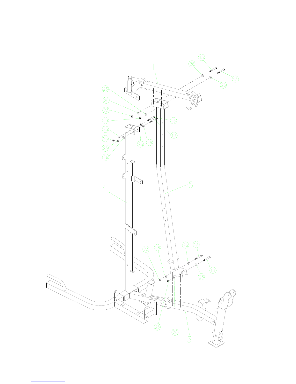
3. Connect backrest tube (5) to seat tube (3) with bolts (M10x75mm)(13) , washers (26) and
locknuts (23). Connect tube (1) to backrest tube (5) and vertical tube (4) with (M10x75mm)(13) ,
washers (26) and locknuts (23).
Page 5
4
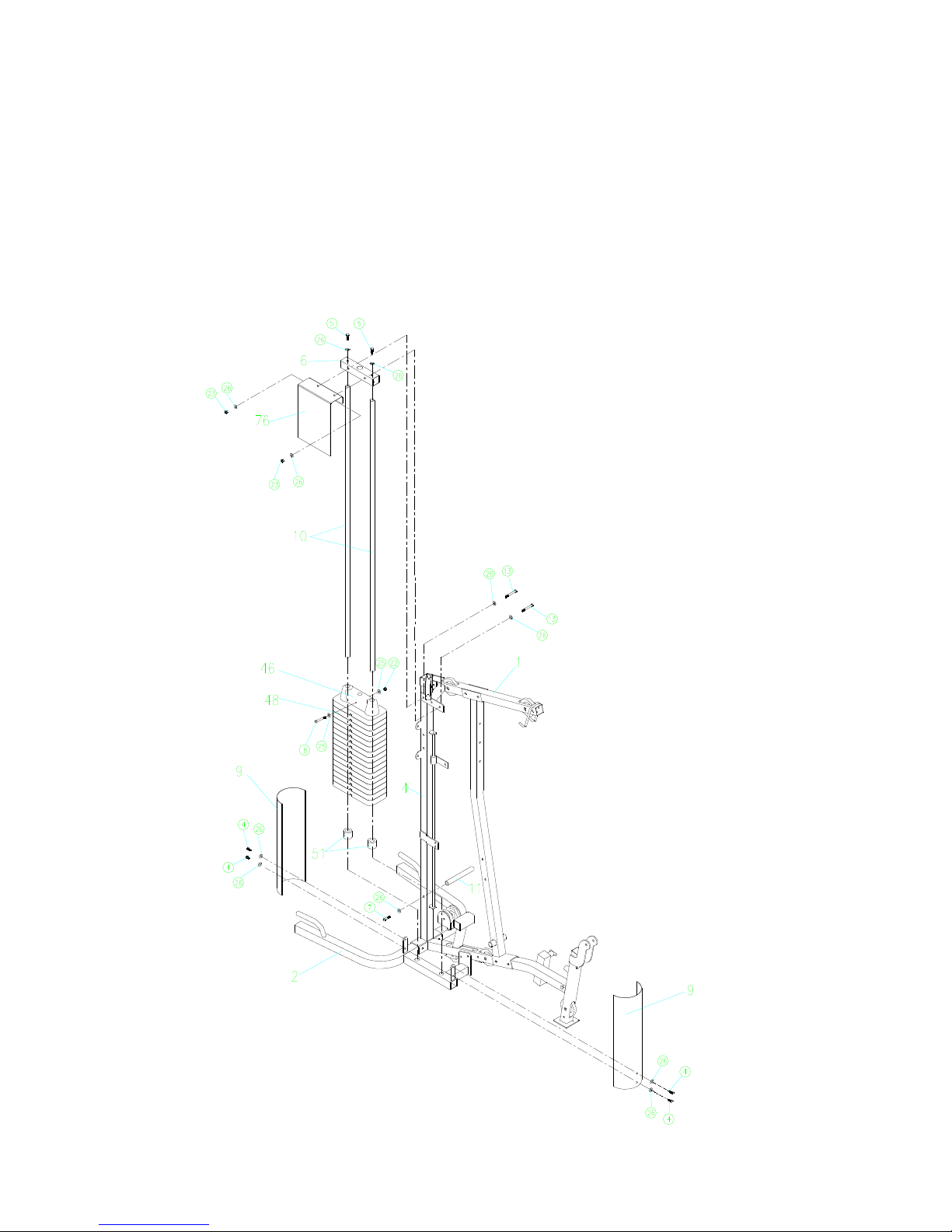
4. Insert leaders (10) into the oriented holes on the bottom of the curl base tube (2), in turn, slide
cover bumpers (51), rubber weight stack (48) and plastic top plate (46). Mount leader top tube(6)
to the leader (10) by washers (26) and bolts (M10x20mm)(5). Connect exercise chart flip (76),
leader top tube (6) and Lab pull down top tube (1) with bolts (M10x75mm)(13), washers (26)
and locknuts (23).
Attach shrouds (9) to the curl base tube (2) with washers (26) and bolts (M10x16mm)(4). Attach
handlebar tube (11) to the vertical tube (4) with washer (26) and bolt (M10x30mm)(7).
Attach plastic briquetting(46) to the leader(22) with bolt(M8x70mm)(8),washers(8)(25) and
locknut(M8)(22).
Page 6
5
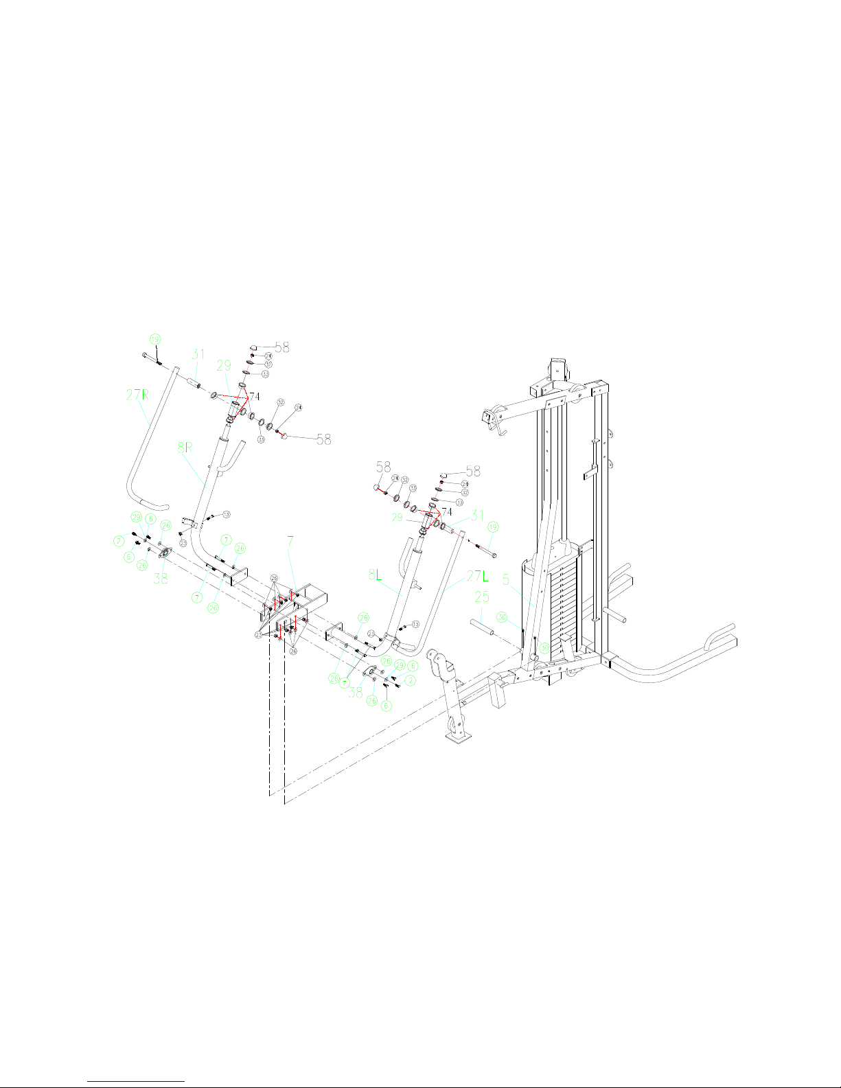
5. Connect backrest tube (5) and chest-extension rotating frame (7) through the rotating bearing
(25), tighten with Hexangular floriated bolt(M8*10mm) (30). Secure bearing bases (38), washers
(26) and bolts (M10x25mm)(6).
Attach chest-extension handlebars (8R&L) to the chest-extension rotating frame (7), which was
already attached to backrest tube (5) in step 4, with washers (26) and bolt (M10x30mm)(7). Slide
crossed bearing covers (29) to the chest-extension handlebars (8R&L), tighten with nut canopy (58).
Connect pulling bar (27R&L) and crossed bearing cover (29) through limiting bushing (31), bolt
(M12x120mm)(19), powder metallurgy bushing (74) ,flat washer (33),dish washer(32) and locknut
(24).
Attach chest-extension handlebars(8L&R) to the fixing tube(50) with bolt(M10x75)(13) and
locknut(M10)(23).
Page 7
6
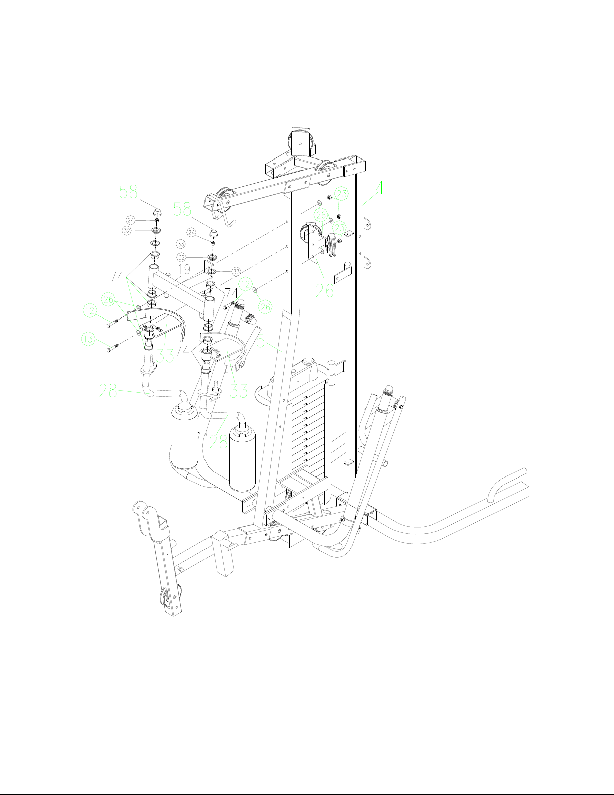
6.Connect the chest-extension frame (19), backrest tube (5) and pulley fixing frame (26) with bolts
(M10x70mm)(12), bolts (M10x75mm)(13), washers (26) and locknuts (23). Fit chest-extension arm
(28), chest-extension adjusting board (33) to chest-extension frame (19) with locknut (24) and
powder metallurgy bushing (74),flat washer(12)(33),dish washer(12)(32),nut canopy(M12)(58).
Page 8
7
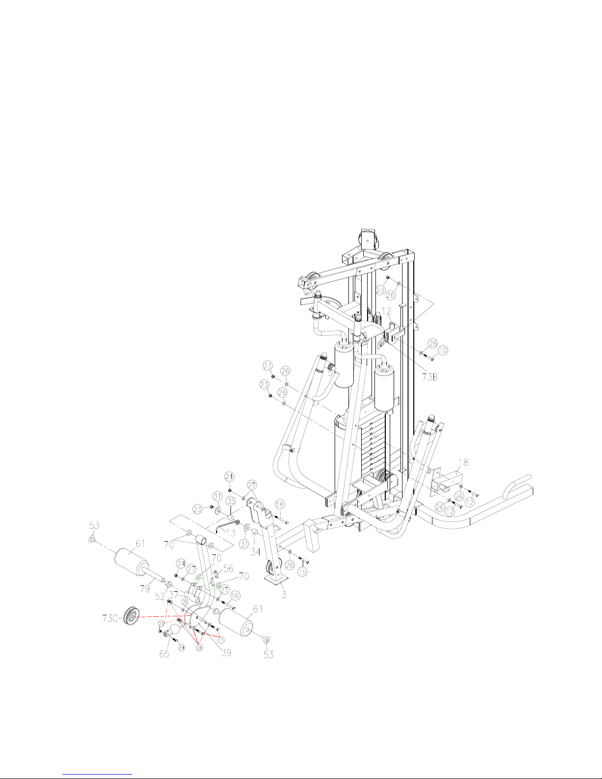
7. Attach oriented hook (13) and zinc bushing(34)、separate ring(35) to seat tube (3) with bolt
(M10x90mm)(15), washer (26), flat washer (31) and locknut (23). Attach rubber cushion (56) to
the back of leg-kicking frame (39).
Connect seat tube (3) and leg-kicking frame (39) with powder metallurgy bushing (70), bolt
(M12x80mm)(18), washers (27) and locknut (24). Attach leg-extension connecting cover (37) to
leg-kicking frame (39) with powder metallurgy bushing (70), bolt (M12x70mm)(16), washers
(27) and locknut (24). Slide tube (79) through the leg-extension connecting cover (37), slide the
bolsters (61) onto both end of the tube, block with leg-kicking sofa hole covers (52) and plastic
briquetting (53).
Attach backrest adjusting bushing (18) to backrest tube (5) with bolt (M10x70mm)(12), washers
(26) and locknut (23). Connect narrow single pulley fork (12), pulley (73B) and pulley limiting
board (17) with bolt (M10x55mm) (10), washers (26) and locknut (23).
Page 9
8
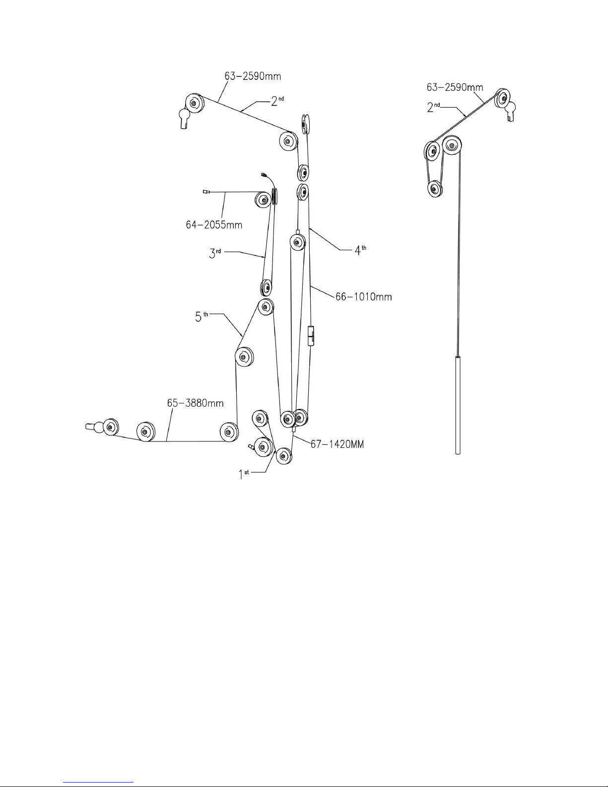
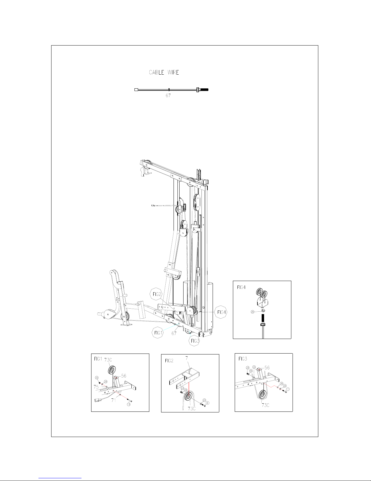
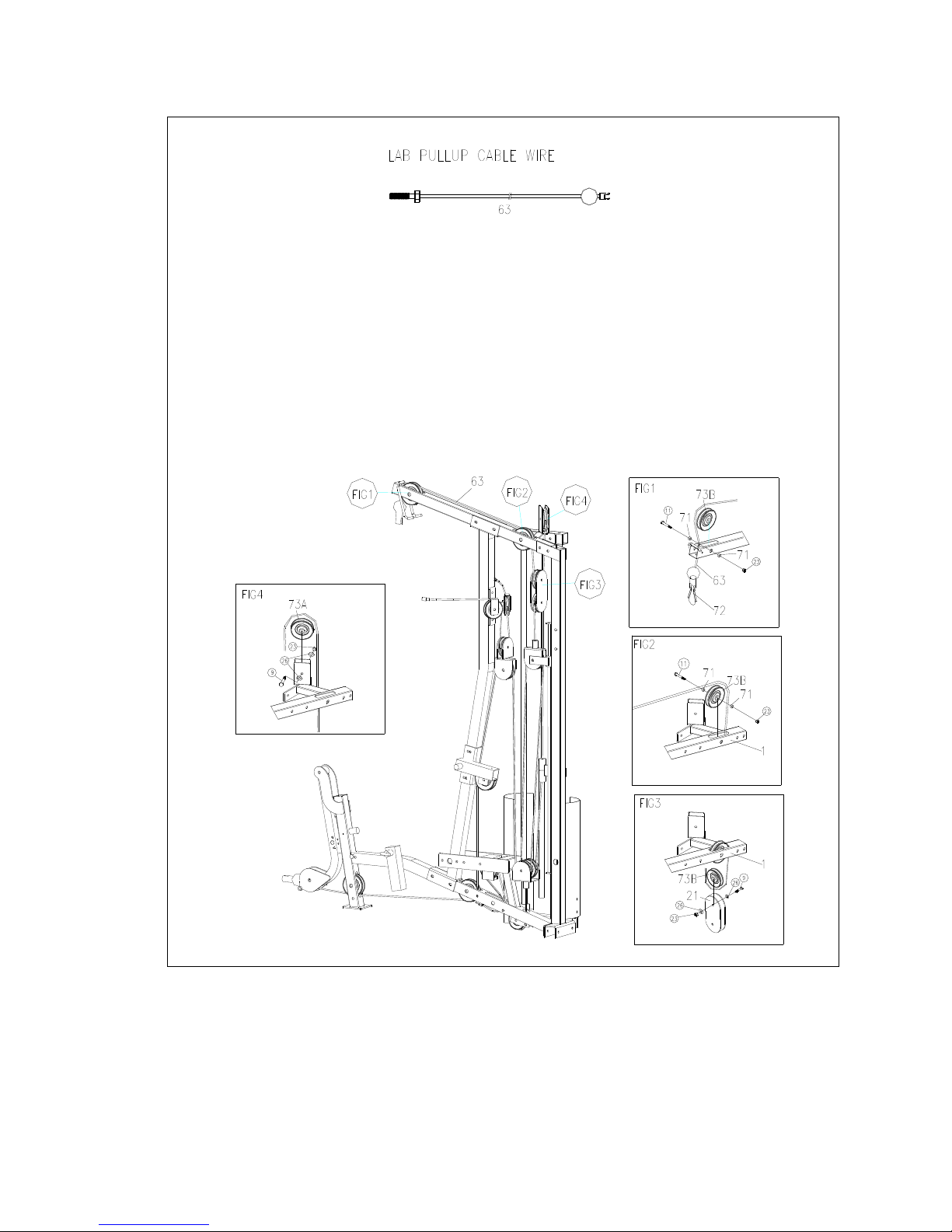
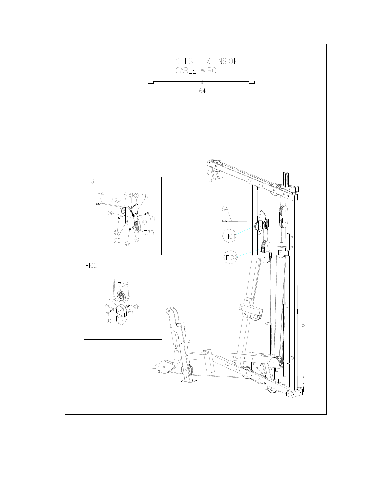
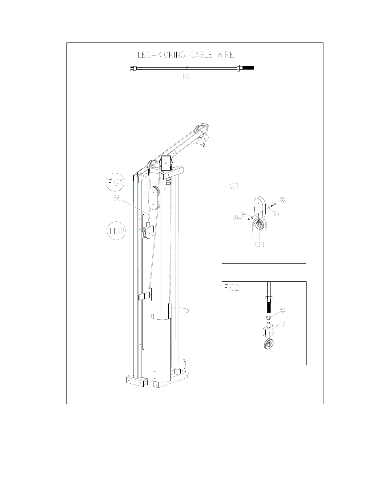
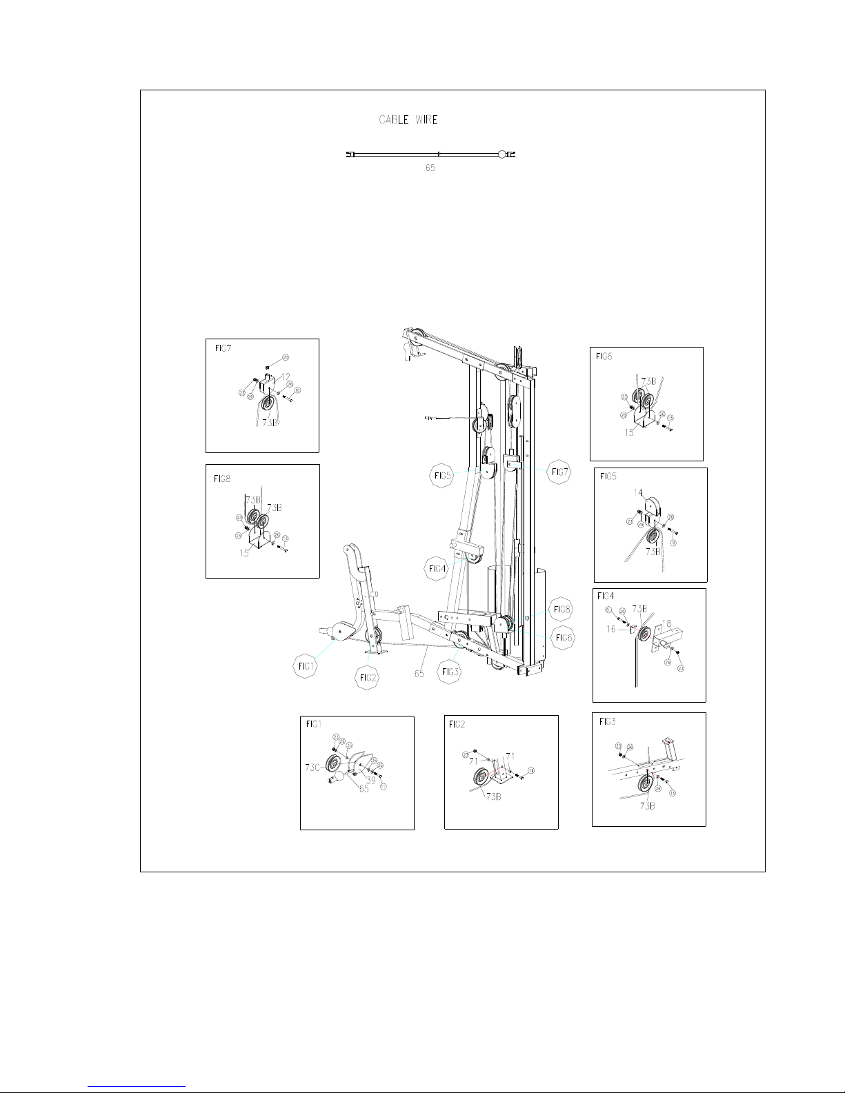
8. Wire circling way:
Cables to be installed in order cable (67) first, cable (63) second, cable (64) third, cable (66) fourth
and cable (65) last. View following 5 pages for figure diagrams.
Page 10
9
The 1
ST
wire: (refer to the following illustration)
Page 11
10
The 2nd wire: (refer to the following illustration)
Page 12
11
The 3rd wire: (refer to the following illustration)
Page 13
12
The 4th wire: (refer to the following illustration)
Page 14
13
The 5th wire: (refer to the following illustration)
Page 15
14
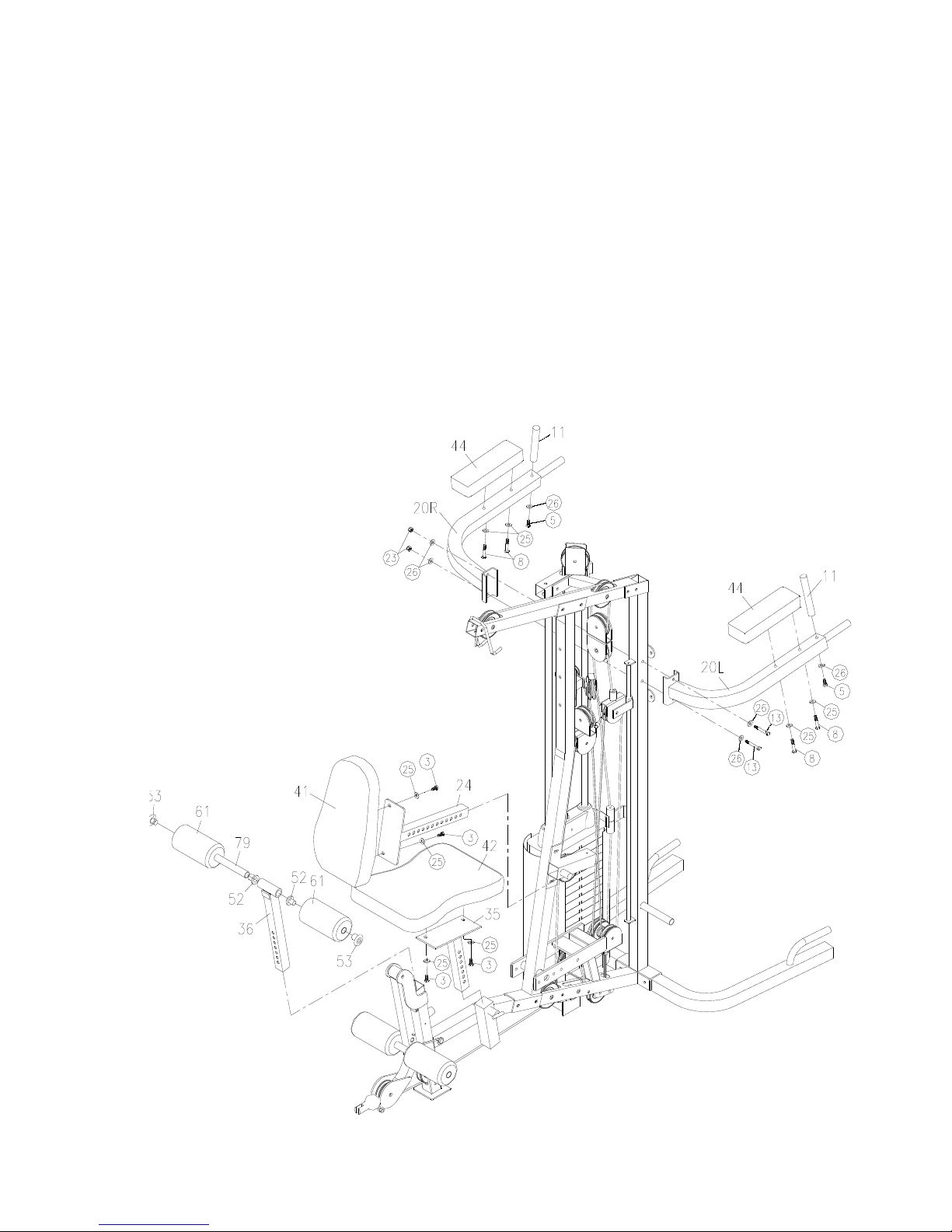
9. Attach handlebar tube (11) to the parallel bar with washer (26) and bolt (M10x20mm)(5). Attach
parallel bar (20) to the vertical tube (4) with bolts (M10x75mm)(13), washers (26) and locknuts
(23).
Attach arm cushion (44) to the parallel bar (20) with washers (25) and bolts (M8x70mm)(8).
Connect backrest cushion (41) and backrest adjusting tube (24) with washers (25) and bolts
(M8x30mm)(3), then insert backrest adjusting tube (24) into backrest adjusting bushing (18),
and lock it with T-shaped adjustable pin (68).
Connect seat adjusting tube (35) and seat cushion (42) with washers (25) and bolts
(M8x30mm)(3), then insert seat adjusting tube (35) into the side bushing on seat tube (3), and
lock it with T-shaped adjustable pin (68).
Slide tube (79) through the leg-kicking adjusting tube (36), slide the bolsters (61) onto both end
of the tube, lock with leg-kicking sofa hole covers (52) and plastic briquetting (53). Insert
leg-kicking adjusting tube (36) into the front bushing on seat tube (3), lock it with T-shaped
adjustable pin (68).
Page 16
15
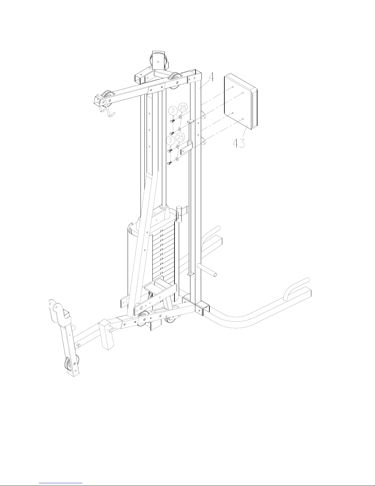
10. Attach backrest cushion (43) to the vertical tube (4) with washers (25) and bolts
(M8x20mm)(2).
Page 17
16
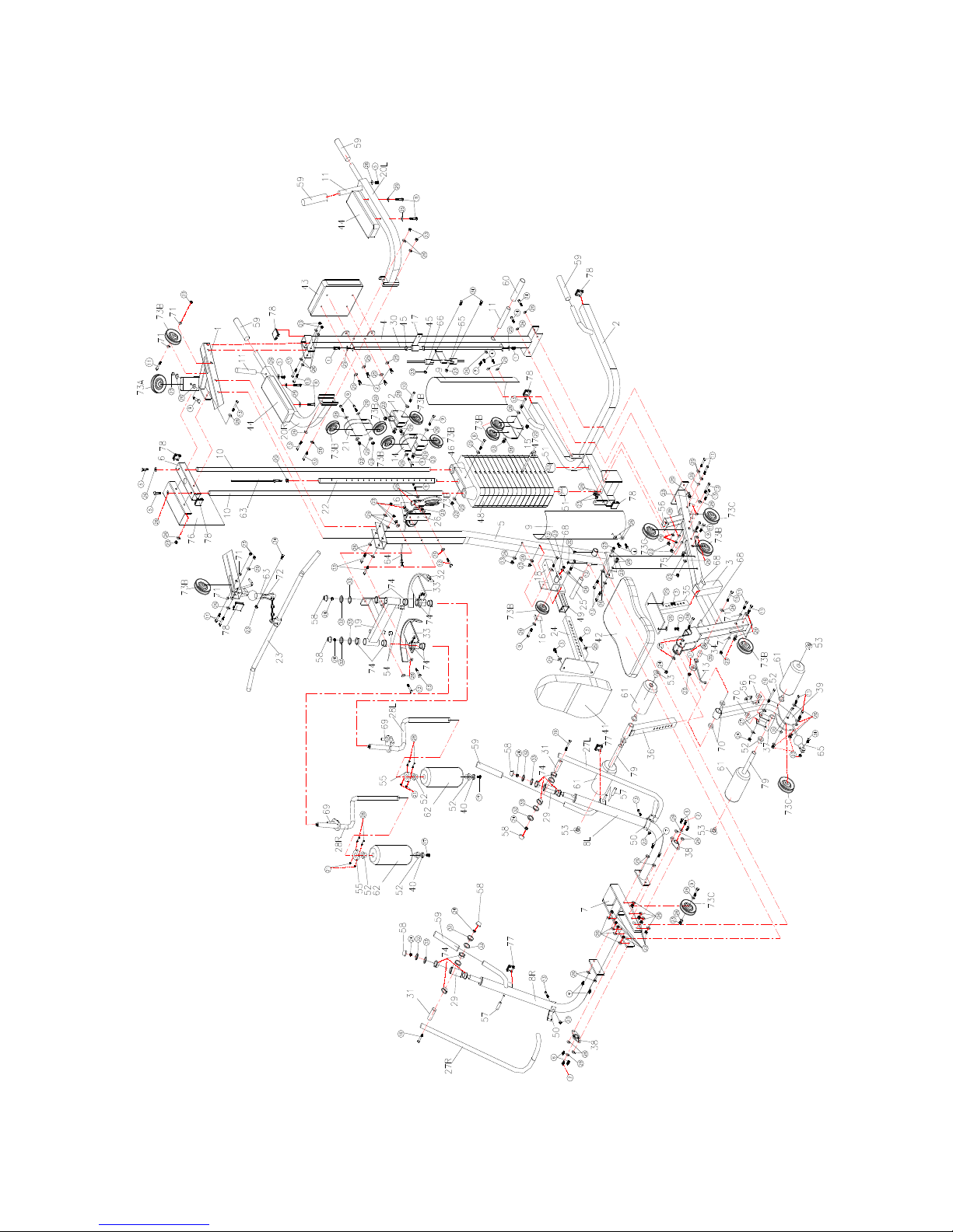
EXPLODED VIEW
Page 18
17
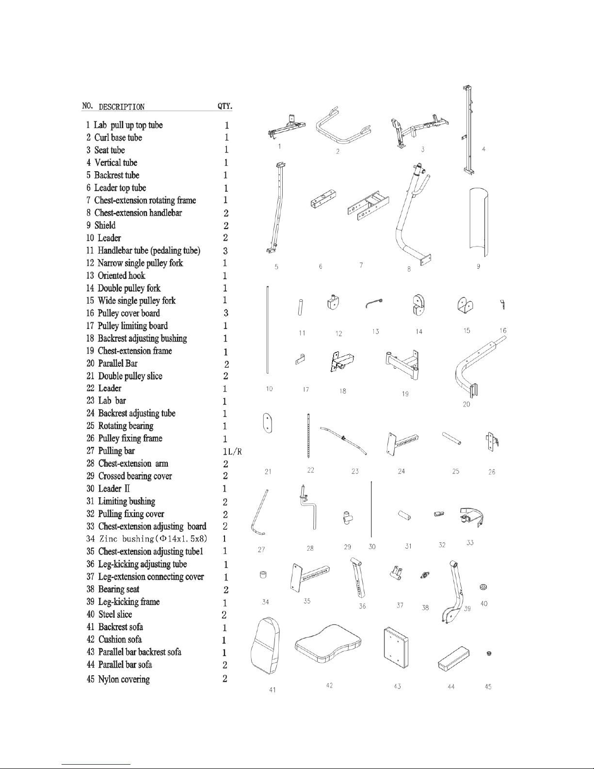
Parts List I
Page 19
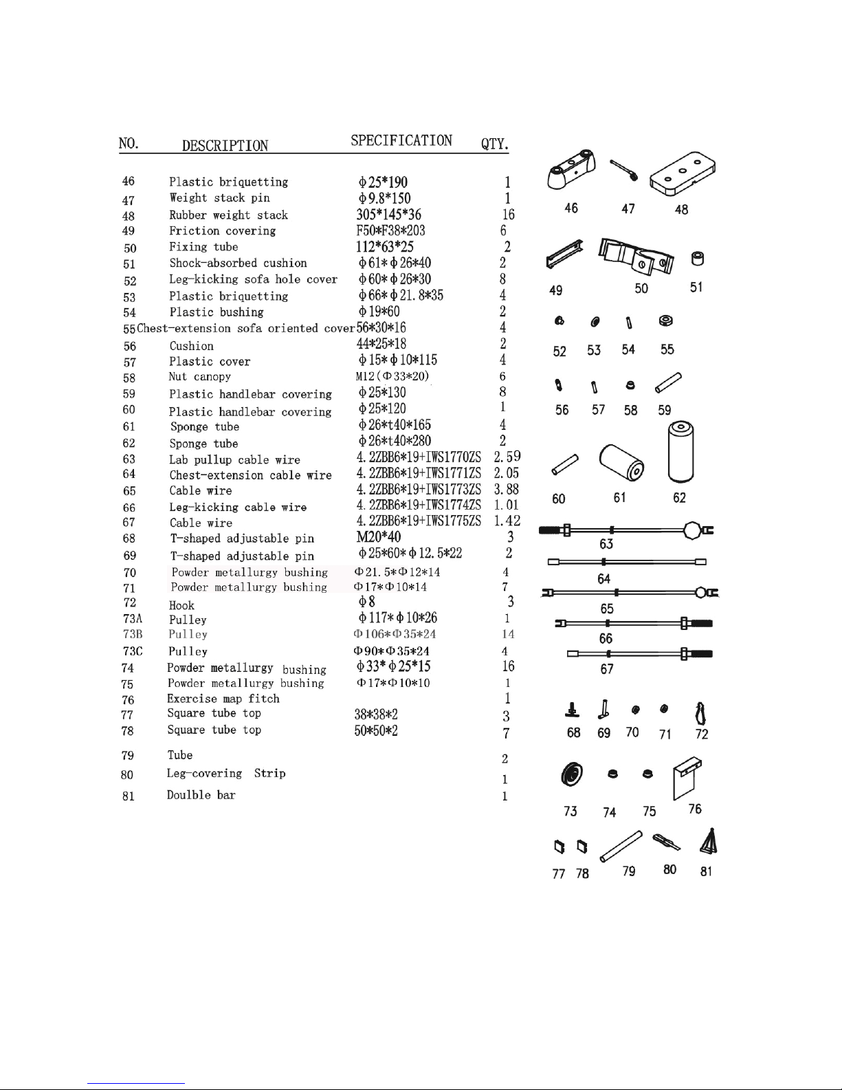
18
Parts List II
Page 20
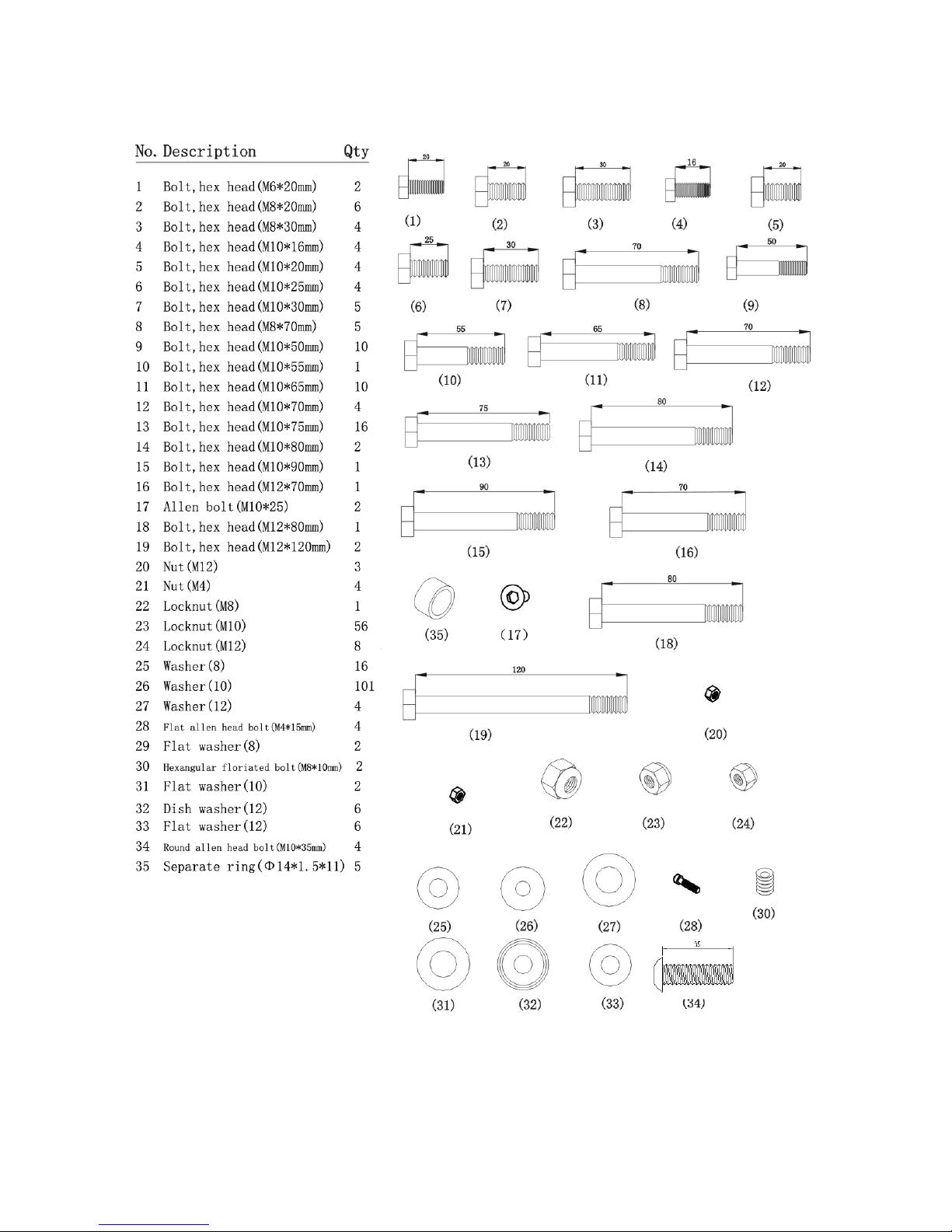
19
Parts List III
Page 21
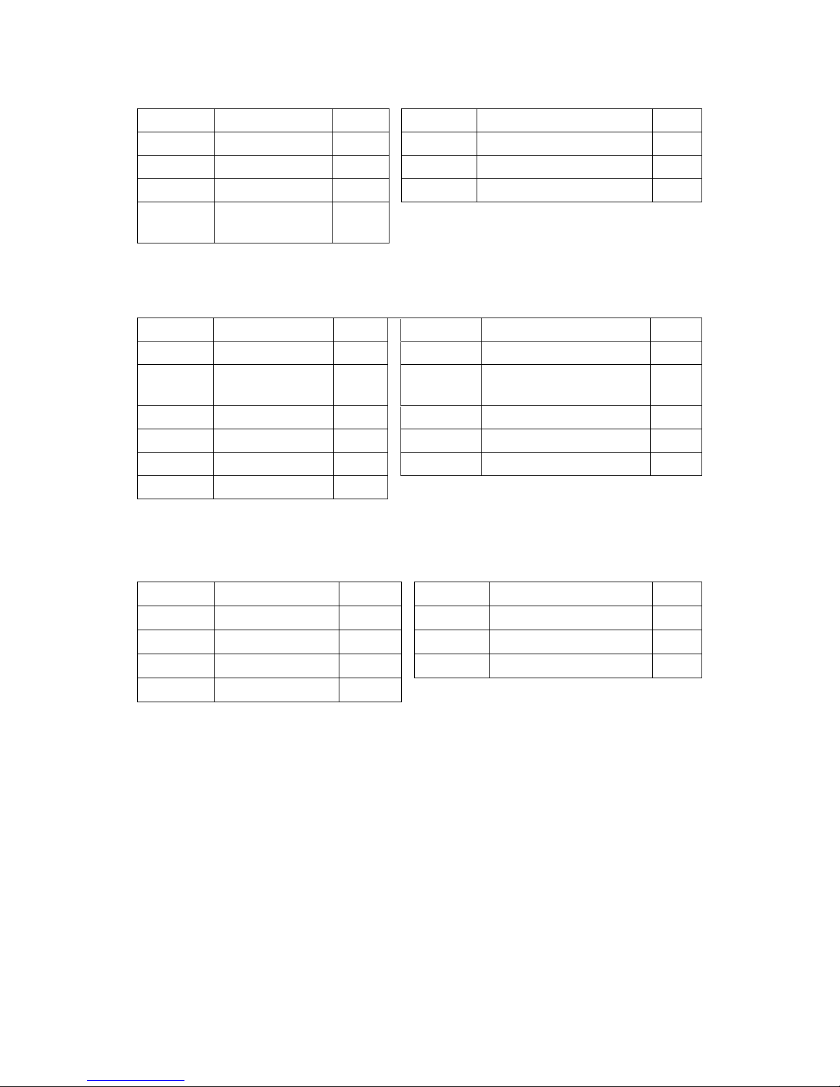
20
1 box of 4; box size: 1295*875*220mm
PART NO. DESCRIPTION QTY. PART NO.
DESCRIPTION QTY.
2 Curl base tube 1
20 Parallel bar 2
3 Seat tube 1
8 Chest-extension handlebar 2
76 Exercise map fitch 1
27/29/31 Pulling bar 2
1
Lab pull up top
tube
1
2 box of 4; box size: 1965*285*220mm
PART NO. DESCRIPTION QTY.
PART NO.
DESCRIPTION QTY.
4 Vertical tube 1
26 Backrest adjusting tube 1
5 Backrest tube 1
35
Chest-
extension adjusting
tube
1
10 Leader 2
36 Leg-kicking adjusting tube 1
30 Leader II 1
28/40 Chest-extension arm 2
22 Leader 1
9 Shield 2
23 Lab bar 1
3 box of 4; box size:675*295*290mm
PART NO. DESCRIPTION QTY.
PART NO.
DESCRIPTION QTY.
42 Seat cushion 1
61 Sponge tube 4
41 Backrest sofa 1
81
Double bar
1
43
Backrest cushion
1
80
Leg-covering strip
1
44
Arm cushion
2
Page 22
21
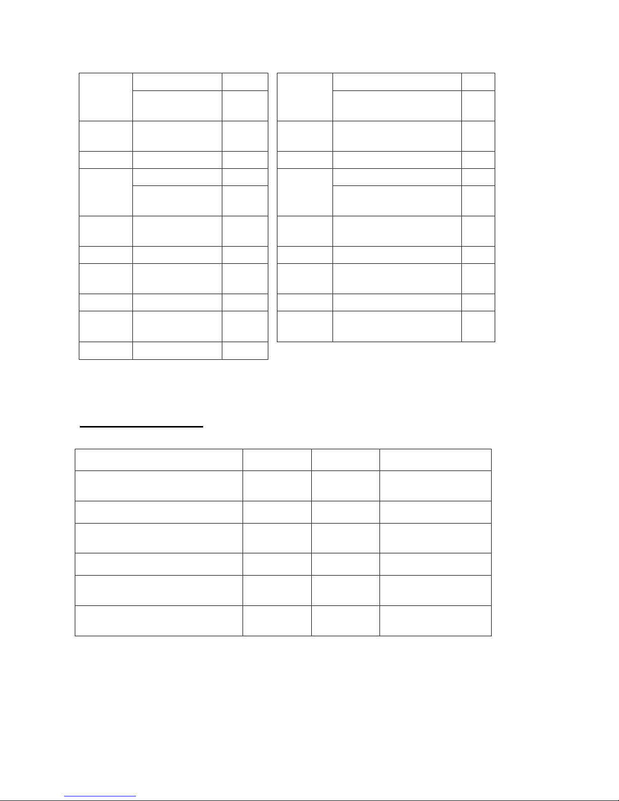
Daily Maintenance
It is recommended that you maintain the equipment as the below chart:
Maintain Every day Every week Every three months
Check: joint, pinning bolt,
pinning bolt of weight stack
√
Clean: sofa and cover
√
Lubricate: Moving and rotating
position.
√
Check if the bolts are tightened
√
Check if the cable wire is loose or
damaged
√
Lubricate: bearing and bearing
seat
√
4 box of 4; box size: 675*365*270mm
PART NO. DESCRIPTION QTY.
PART NO.
DESCRIPTION QTY.
19/54
Chest-extension
frame
1
33/32
Adjusting board/P
ulling
fixing cover
2
7
Chest-extension
rotating frame
1
11
Handlebar tube (pedaling
tube)
3
46 Plastic briquetting
1
18/49
Backrest adjusting bushing
1
39 Leg-kicking frame
1
51 Bumper 2
14
Double pulley fork
1
63/64/65/
66/67
Cable 5
15
Wide si
ngle pulley
fork
1
38 Bearing base 2
21 Double pulley slice
1
25 Rotating bearing 1
12/17/45
Narrow single
pulley fork
1
13 Oriented hook 1
79 Tube 2
50 Fixing tube nip 2
6 Leader top tube 1
37
Leg-
extension connecting
cover
1
26 Pulley fixing frame
1
 Loading...