

Orbit LWP25-80W, LWP25-100W-480V, LWP25-40W-480V, LWP25-120W, LWP25-50W Installation Instructions Manual
...
Category:
Orbit Industries, Inc.
LWP25 - SERIES
INSTALLATION INSTRUCTIONS
WARNING: All work must be performed by qualified electrician. Luminaire must be installed and grounded in
accordance with the National Electrical Code (NEC) and local codes. Failure to do so may result in serious
injury and/or damage to the luminaire.
WARNING: To avoid risk of fire, explosion, or electric shock, this product should be installed, inspected, and
maintained by a qualified electrician only and in accordance with all applicable codes.
WARNING: To avoid electric shock:
Be certain electrical power is OFF before and during installation and maintenance.
Luminiare must be connected to a wiring system with an equipment grounding conductor.
WARNING:
Make sure the supply voltage is the same as the rated luminaire voltage.
Do not operate in ambient temperatures above those indicated on the luminaire nameplate.
Keep lens tighly closed when in operation.
NOTE: Save these instructions for future reference.
NOTE: PHOTOCELL IS EITHER 120V OR 277V, BEFORE INSTALLING CHECK SUPPLY VOLTAGE.
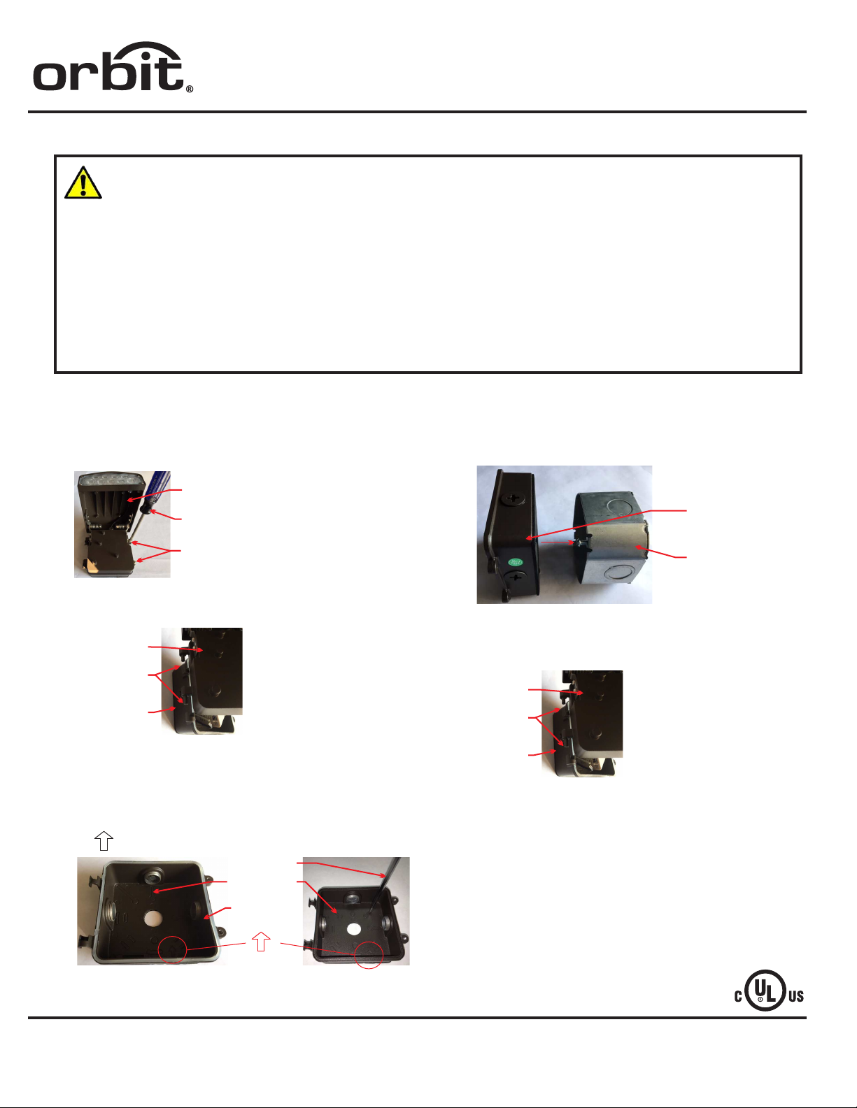
4. Install the fixture junction box to the wall junction
JUNCTION BOX (WALL) MOUNT:
1. Open the fixture head at least 90 degree
to loosen the two screws by screw driver.
FIXTURE HEAD
SCREW DRIVER
box (3O or 4O steel boxes). Remove one screw
of the wall junction box and install the slot of
fixture junction box.
100~277V
347~480V
FIXTURE JUNCTION BOX
SCREWS
2. Open and lift the fixture head from the junction box
from the hinge.
FIXTURE HEAD
HINGE
JUNCTION BOX
3. Fixture junction box has a guided pre-punch
holes. Check your wall junction box mounting
screws and knock-out the pre-punch holes
by a screw driver.
NOTE: Before punching the holes, check the
UP direction.
SCREW DRIVER
PRE-PUNCH HOLES
FIXTURE
JUNCTION BOX
UP
WALL JUNCTION BOX
NOTE: ABOVE PICTURE IS FOR ILLUSTRATION PURPOSES ONLY.
IT MAY DIFFER IN ACTUAL INSTALLATIONS.
5. Re-install the fixture head thru the hinge of the
fixture junction box.
FIXTURE HEAD
HINGE
JUNCTION BOX
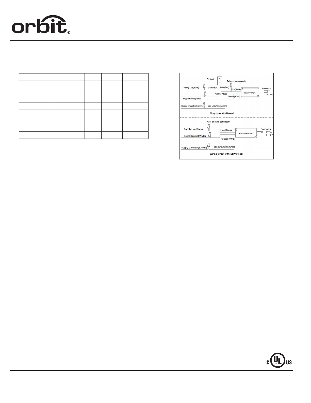
6. Attach fixture leads to line observing polarity,
black to black, white to white and green to
ground to junction box.
7. Close the fixture and tighten the two screws.
Check GASKET if sitting properly.
For better waterproofing apply a silicone
around the fixture junction box and wall
surface.
If 1/2” threaded holes on the sides is used,
apply a silicone after installation.
8. Adjust the fixture to a proper angle.
9. Turn ON power and check for proper
operation.
2100 S. Figueroa St. Los Angeles, CA 90007
Tel (213) 745-8884 Fax (213) 745-2015
www.orbitelectric.com
Orbit Industries, Inc.
INSTALLATION INSTRUCTIONS
Category:
LWP25 - SERIES
100~277V
347~480V
MODEL NO.
LWP25-12W 100~277V
LWP25-30W 100~277V
LWP25-40W 100~277V
LWP25-40W-480V 347~480V
LWP25-50W 100~277V
LWP25-80W 100~277V
LWP25-100W-480V
LWP25-120W 100~277V
INPUT VOLTAGE
347~480V
WATTS
12W
30W
40W
75W
50W
50W
100W
120W
INPUT AMP.
0.15A
0.38A N/A
0.44A
0.22A 0-10V/PWM/VR
0.52A
1.0A
0.48A
1.5A
DIMMING
N/A
N/A
N/A
0-10V/PWM/VR
0-10V/PWM/VR
0-10V/PWM/VR
2100 S. Figueroa St. Los Angeles, CA 90007
Tel (213) 745-8884 Fax (213) 745-2015
www.orbitelectric.com
 Loading...