

Page 1
295 lbs/135 kgs.
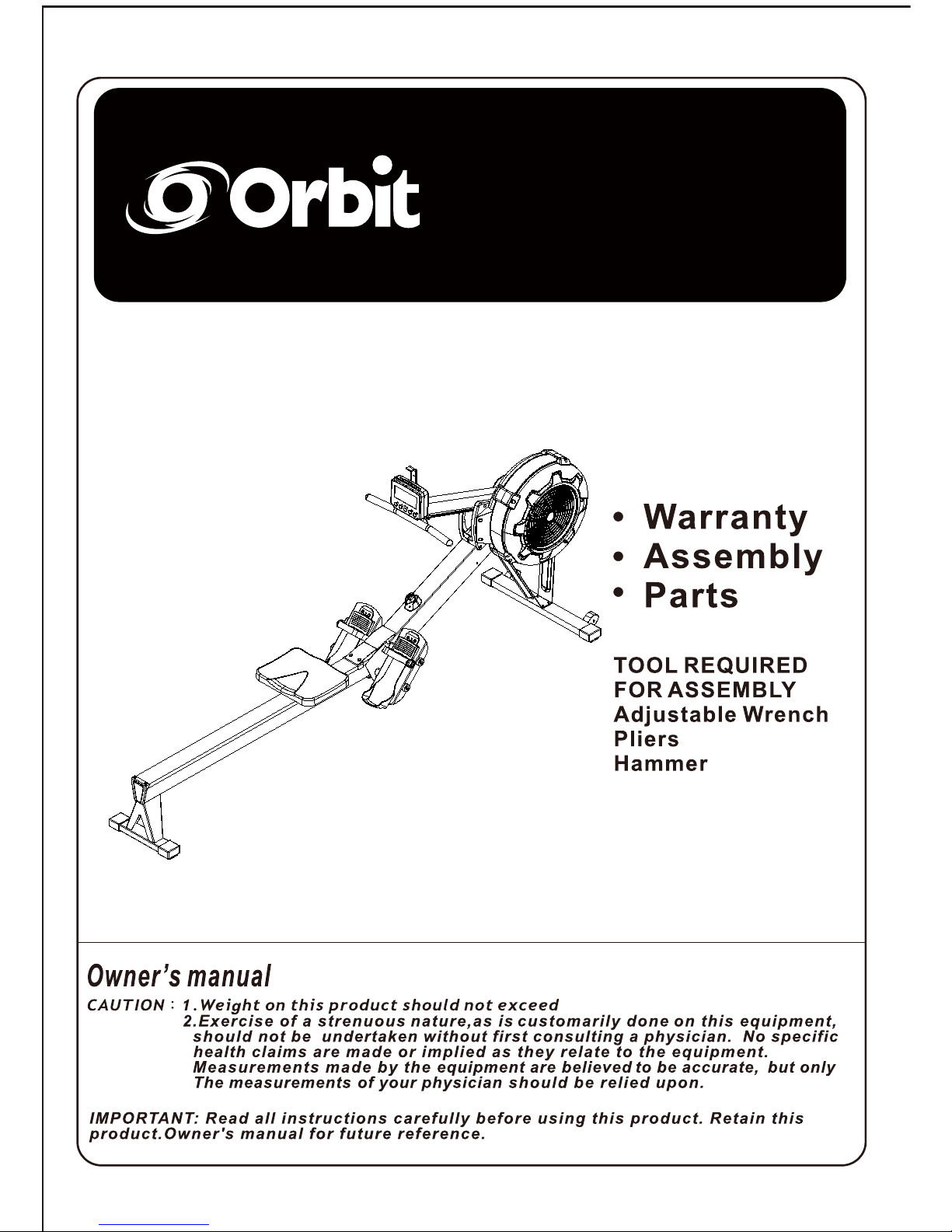
ERGO6.0
ERGO6.0
ERGO6.0
Page 2

2
TABLE OF CONTENTS
Safety Instructions ...................................... 2
Before You Begin ........................................ 4
Equipment Warning, Caution Labels………5
Hardware Identification Chart ................... 6
Assembly Instructions .............................. 7
Computer Instructions ...............................11
Operational Instructions ..........................18
Maintenance ...............................................19
Storage........................................................ 20
Conditioning Guidelines............................21
Warm-Up and Cool-Down........................... 22
Warranty......................................................23
Product Parts Drawing............................... 24
Parts List..................................................... 25
SAFETY INSTRUCTIONS
! WARNING
Cancer and Reproductive Harm www.P65Warnings.ca.gov
! WARNING
! WARNING
Consult your physician before starting this or any exercise program. This is
especially important if you are over the age of 35, have never exercised before,
are pregnant, or suffer from any health problem. This product is for home use
only. Do not use in institutional or commercial applications. Failure to follow all
warnings and instructions could result in serious injury or death.
To reduce the risk of serious injury, read the following Safety Instructions
before using the ERGO6.0 AIR ROWER.
1.
Save these instructions and ensure that other exercisers read this manual prior to using the
ERGO6.0 AIR ROWER
for the first time.
2.
Read all warnings and cautions posted on the
ERGO6.0 AIR ROWER.
3.
The
ERGO6.0 AIR ROWER
should only be used after a thorough review of the Owner’s Manual. Make sure
that it is properly assembled and tightened before use.
4.
We recommend that two people be available for assembly of this product.
5.
Keep children away from the
ERGO6.0 AIR ROWER.
Do not allow children to use or play on the
ERGO6.0 AIR ROWER.
Keep children and pets away from the
ERGO6.0 AIR ROWER
when it is in use.
6.
It is recommended that you place this exercise equipment on an equipment mat.
7.
Set up and operate the
ERGO6.0 AIR ROWER
on a solid level surface. Do not position the
ERGO6.0 AIR ROWER
on loose rugs or uneven surfaces.
8.
Make sure that adequate space is available for access to and around the
ERGO6.0 AIR ROWER.
9.
Before using, inspect the
ERGO6.0 AIR ROWER
for worn or loose components, and securely tighten or
replace any worn or loose components prior to use.
10.
Before using, check the condition of the CHAIN(36). Replace the CHAIN(36) if it is cracked or broken.
11.
Consult a physician prior to commencing an exercise program and follow his/her recommendations in developing
your fitness program. If at any time during exercise you feel faint, dizzy, or experience pain, stop and consult your
physician.
12.
Always choose the workout which best fits your physical strength and flexibility level. Know your limits and train
within them. Always use common sense when exercising.
13.
Do not wear loose or dangling clothing while using the
ERGO6.0 AIR ROWER.
14.
Never exercise in bare feet or socks; always wear proper footwear such as running, walking, or cross training
shoes that fit well, provide foot support, and feature non-skid rubber soles.
15.
Be careful to maintain your balance while using, mounting, dismounting, or assembling the
ERGO6.0 AIR
ROWER,
loss of balance may result in a fall and bodily injury.
16.
Do not use the SEAT(51) to move the
ERGO6.0 AIR ROWER.
The SEAT(51) will move and the SEAT
CARRIAGE(10) may pinch your hand or fingers. When assembling or separating the unit, keep all children
away and make sure your hands are clear of any pinch point.
17.
The
ERGO6.0 AIR ROWER
should not be used by persons weighing over 300 pounds.
18.
The
ERGO6.0 AIR ROWER
should be used by only one person at a time.
19.
The
ERGO6.0 AIR ROWER
is for consumer use only. It is not for use in public or semipublic facilities.
Central Time Friday, 8:00 AM-3:00 PM, Centr
Page 3
4
BEFORE YOU BEGIN
Thank you for choosing the ERGO6.0 AIR
ROWER. We take great pride in producing this
quality product and hope it will provide many hours
of quality exercise to make you feel better, look
better, and enjoy life to its fullest.
It's a proven fact that a regular exercise program
can improve your physical and mental health.
Too often, our busy lifestyles limit our time and
opportunity to exercise. The ERGO6.0 AIR
ROWER provides a convenient and simple method
to begin your journey of getting your body in shape
and achieving a happier and healthier lifestyle.
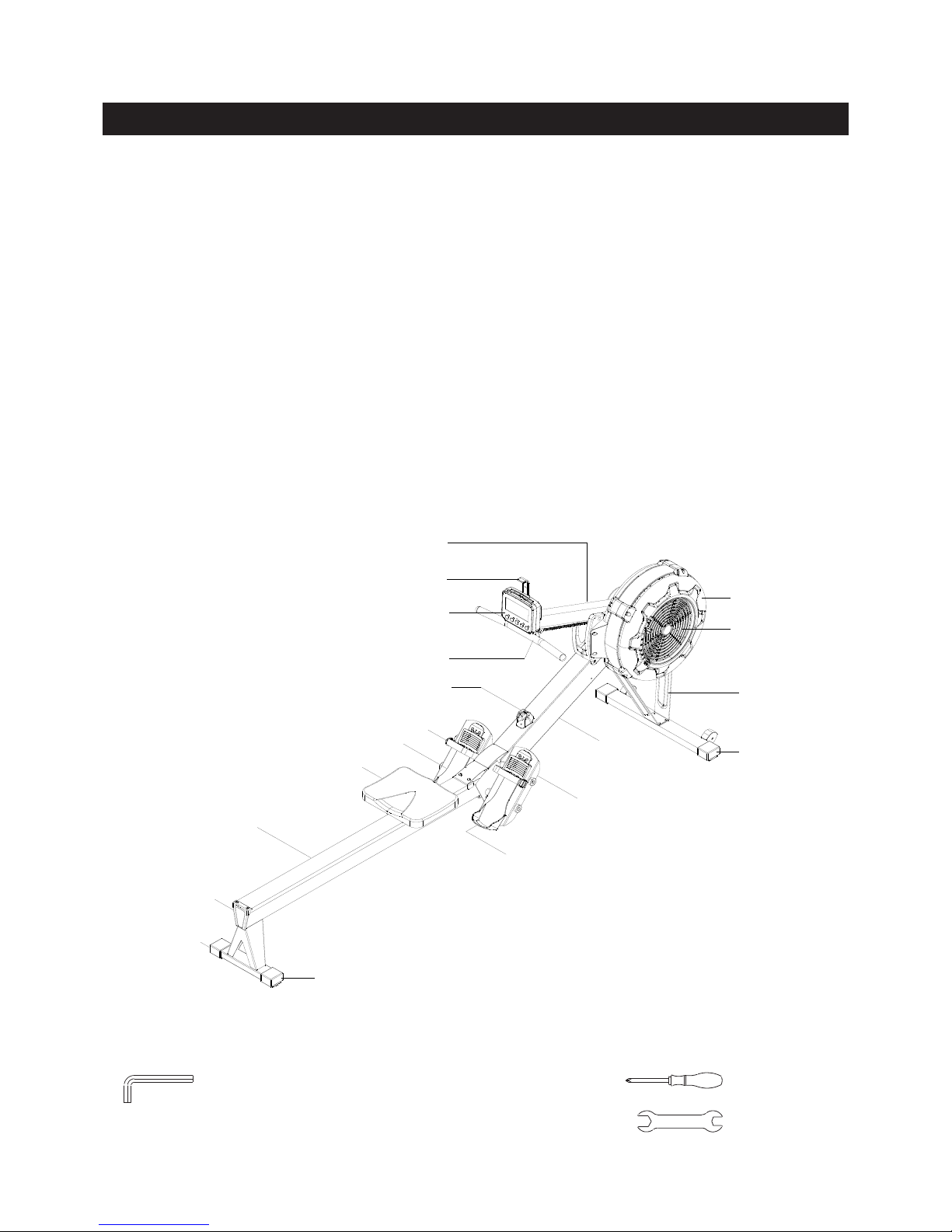
Before reading further, please review the
drawing below and familiarize yourself with the
parts that are labeled.
Read this manual carefully before using the
ERGO6.0 AIR ROWER.
THE FOLLOWING TOOLS ARE INCLUDED FOR ASSEMBLY :
Allen Wrench (6mm) Screwdriver
Allen Wrench (5mm)
Wrench
Computer Post
Cell Phone Bracket
Computer
Handlebar
Handlebar Holder
Pedal Strap
Pedal Cap
Seat
Rail Frame
Rail Cap
Endcap
Endcap
Endcap
Pedal Cap
Pedal Support
Main Frame
Right Fan Cage
Damper
Support Leg
Page 4
5
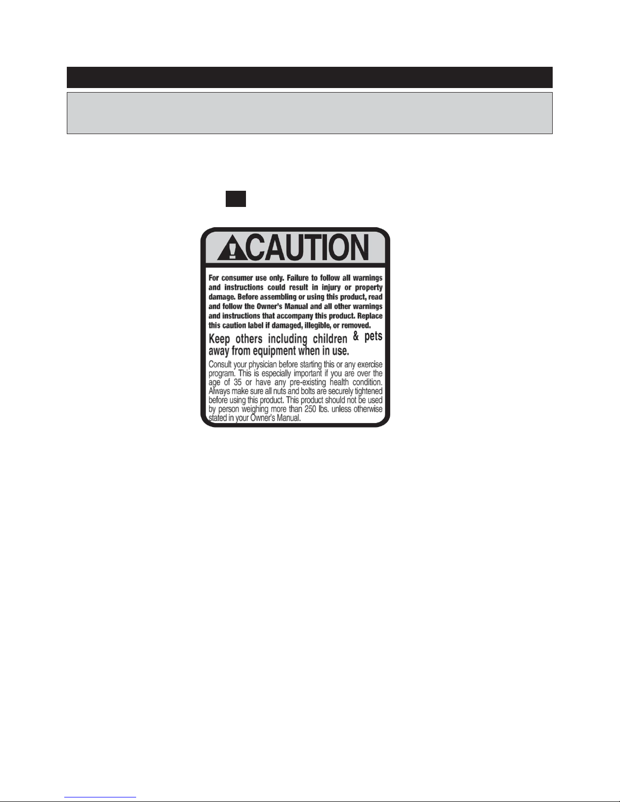
EQUIPMENT WARNING, CAUTION LABELS
This chart is provided to help identify the warning, caution, and notice labels on the ERGO6.0
AIR ROWER. Please take a moment to familiarize yourself with all of the warning, caution, and
notice labels.
Label is larger than actual size
C1 CAUTION LABEL
Page 5
6
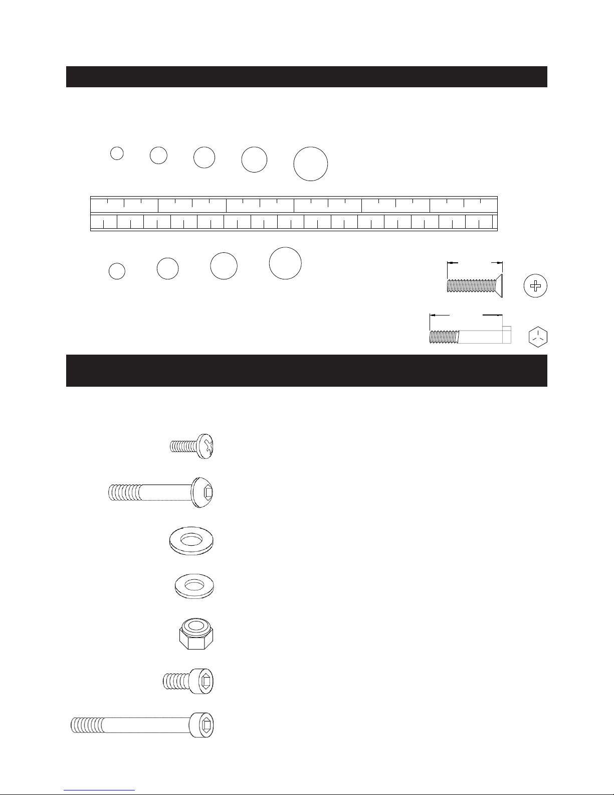
HARDWARE IDENTIFICATION CHART
This chart is provided to help identify the fasteners used in the assembly process. Place the washers or
the ends of the bolts or screws on the circles to check for the correct diameter. Use the small scale to
check the length of the bolts and screws.
3/16" 1/4" 5/16" 3/8" 1/2"
INCHES
0 1/2 1 1/2 2 1/2 3 1/2 4 1/2 5 1/2 6
in.
0 10 20 30 40 50 60 70 80 90 100 110 120 130 140 150
mm.
MILLIMETERS
length
6 8 10 12
NOTICE: The length of all bolts and screws, except those with flat
heads, is measured from below the head to the end of the bolt
or screw. Flat head bolts and screws are measured from the
top of the head to the end of the bolt or screw.
length
After unpacking the unit, open the hardware bag and make sure that you have all the following
fasteners. Some fasteners may be already attached to the parts.
Part Number and Description Qty
72 Bolt, Round Head (M6 x 1 x 10mm) 2
78 Bolt, Button Head (M8 x 1.25 x 75mm) 1
79 Washer (M8) 1
76 Washer (M6) 8
80 Nylock Nut (M8 x 1.25) 1
81 Bolt, Socket Head (M6 x 1 x 16mm) 8
84 Bolt, Socket Head (M8 x 1.25 x 150mm) 4
Page 6
7
ASSEMBLY INSTRUCTIONS
ASSEMBLY INSTRUCTIONS
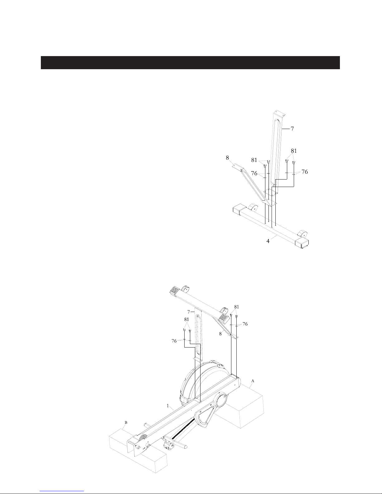
STEP 1
Attach FRONT SUPOORT LEG A(7) and FRONT SUPPORT LEG B(8) to FRONT
STABILIZER(4) using: M6X16mm SOCKET HEAD CAP SCREW(81) and M6 FLAT
WASHER(76).
NOTE: Do not fully tighten bolts until instructed.
STEP 2
Attach FRONT SUPPORT LEG A(7) and FRONT SUPPORT LEG B(8) to MAIN FRAME(1)
using: M6X16mm SOCKET HEAD CAP SCREW(81) and M6 FLAT WASHER(76).
NOTE: Complete this step before taking the item out from its packing material styrofoam A and B.
Page 7
8
ASSEMBLY INSTRUCTIONS
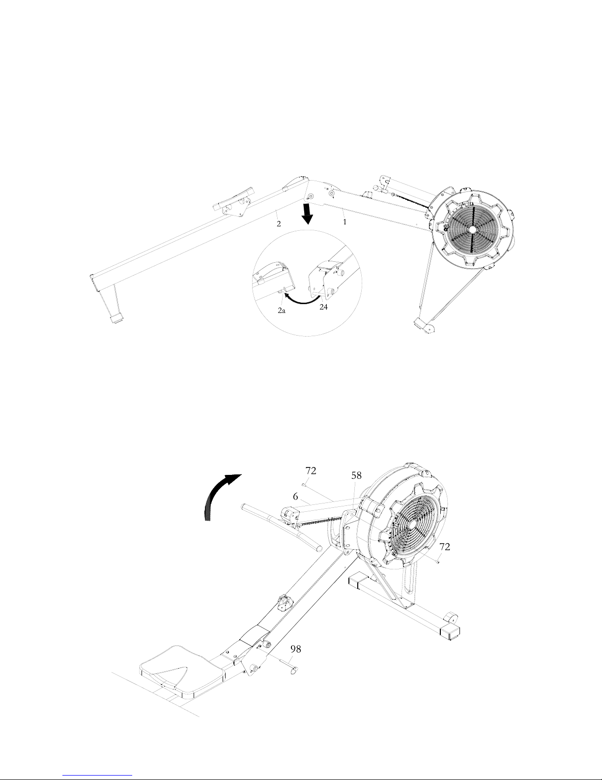
STEP 3
Lift up the MAIN FRMAE(1) and RAIL FRAME(2), then insert RAIL FRAME(2) into the MAIN
FRMAE(1). Fit the SHAFT(24) on the MAIN FRAME(1) into the gap of the RAIL FRAME(2).
NOTE: Fully tighten bolts at end of this step.
STEP 4
Insert the PULL PIN(98) into the MAIN FRAME(1) and RAIL FRAME(2).
Attach CONSOLE MONITOR POST(6) to the SIDE COVERS (57)(58): M6X10 PHILLIPS HEAD
SCREW(72).
NOTE: Fully tighten bolts at end of this step.
Page 8
9
ASSEMBLY INSTRUCTIONS
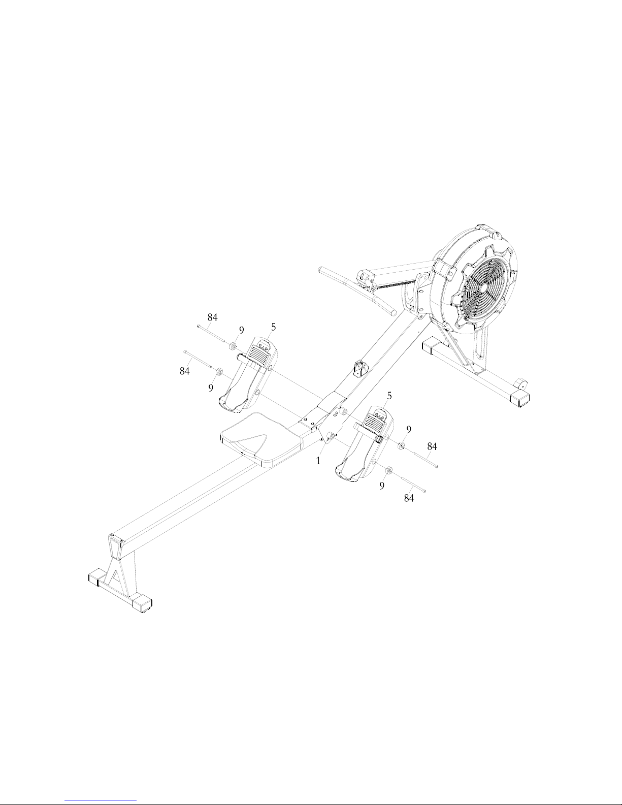
STEP 5
Attach PEDAL SUPOORT PLATEs(5) to the MAIN FRAME(1) using: M8X150mm SOCKET
HEAD CAP SCREW(84) and FOOT PEDAL END CAP(9).
NOTE: Fully tighten bolts at end of this step.
Page 9

COMPUTER INSTRUCTIONS
10
STEP6
Attach CELL PHONE BRACKET(20) to the CONSOLE MONITOR(19) using RUBBER
BAND(21).
STEP
7
Attach the CONSOLE MONITOR(19) to the CONSOLE MOUNTING BRACKET(69) using:
M8X75mm BUTTON HEAD CAP SCREW(78), M8 FLAT WASHER(79), and M8 NYLON LOCK
NUT(80).
STEP
8
Connect SENSOR CABLE(23) into the back of the CONSOLE MONITOR(19a).
Finish
Page 10

COMPUTER INSTRUCTIONS
11
COMPUTER INSTRUCTIONS
Your ERGO6.0 AIR ROWER utilizes an air fan system to create resistance for your workout. We
recommend that you use this computer console to vary your workout from session to session and note
your progress toward your fitness goals. When used regularly in this way, the computer console can
become an important source of motivation and interest which will help keep you on track.
POWER ON: Move the handlebar or press any button.
POWER OFF: In IDLE mode, automatically shuts off after 20 seconds of inactivity.
During workout, except running an Interval Program, a after 30 seconds of inactivity.
When running an Interval Program, automatically shuts off after two minutes of inactivity
FUNCTION BUTTONS:
SELECT : In IDLE mode, press and release SELECT to cycle through each program option. Stop
on the program of your choosing. You can preset target values for DISTANCE, TIME, and
CALORIES, play the GAME, or select an Interval Program of 20/10, 10/20, or 10/10.
(UP) : Press to increase the preset values. Press the button and hold it down, the presetting
value will go faster, release the button to stop.
(DOWN) : Press to decrease the preset values. Press the button and hold it down, the presetting
value will go faster, release the button to stop.
BACK : When selecting the programs, press the button to return to the previous program.
When you finish a running program, press the button to jump into the IDEL model.
ENTER/STOP : When selecting the programs and presetting target values, press the button to confirm.
Press the button and hold it down for three seconds to reset all functions to zero and
restart the computer.
During exercise, when back light is turned off, the first pressing of this button will turn on
the back light. When the back light is still lit, press the button a second time to pause the
counting of all function values. Press the button a third time to restart the workout and
continue of the counting of all function values.
Page 11

COMPUTER INSTRUCTIONS
12
LCD DISPLAY INSTRUCTIONS
1. Stroke
1.1 Stroke value sums up for every stroke.
2. Stroke Rate
2.1 Stroke Rate displays how many strokes in each minute.
2.2 The semicircle equals to stroke rate when in workout mode.
3. Time
3.1 Display range: 00:00 ~ 99:59 (Min: Sec)
3.2 The workout time is accumulated when under any workout mode.
3.3 Time counting backwards under Time mode, displays how much time is left. Setting
range is 0-99.
3.4 Time won’t be saved under User intermittent mode. Setting range is 10 ~ 99.
4. Distance
4.1 Distance counting range is 0 ~ 9999 Meter. If it’s over 9999 Meter, distance will
recalculate from 0.
4.2 The distance is accumulated when under any workout mode.
4.3 Under Distance mode, distance counts backward. Setting range 500 Meter〜9999
Meter.
5. Cycle
5.1 Under intermittent modes, cycle value displays present workout period. Setting
range is 1~99. Pre-set value is 8.
6. Pulse
6.1 Display range is 40~ 220 bpm.
6.2 When pulse has been sensed, the heart symbol flashes in the Pulse window and
shows value.
6.3 Pulse window displays nothing if heartbeat not being sensed.
Page 12

COMPUTER INSTRUCTIONS
13
7. Calories:
7.1 Calories convert by each stroke/row. Range is 0~999
(Calories/Hour = Kcal/ht = (Watts)*4*0.8604+300)
7.2 Calories mode counts backward. Setting range is 10cal〜999cal.
8. Watts
8.1 Watts convert by each stroke/row. (Watts=2.80 / (sec/meter)^3)
8.2 If watts over 999, display shows 999.
9. Paddle width
9.1 Display range: 0~99M
9.2 Display current distance of each stroke/row.
9.3 Distance of each stroke/row
9.3.1 1 Metric Units: Each stroke/row = 2.094*paddle wave/100 (Meter)
9.3.2 Imperial Units: Each stroke/row = (2.094*paddle wave/100) /0.3048 (Feet)
9.3.3 1 Feet = 0.3048 Meter
10. Low battery reminder
10.1 The low battery symbol appears only when the battery is low.
10.2 No back light when in low battery.
11. Buzzer
11.1 The “beep” sound appears when any effective button has pushed.
11.2 If function is ineffective, no sound.
PROGRAM DESCRIPTIONS
This console monitor contains the following programs: (1) Normal, (2) Distance, (3) Time, (4)
Calories, (5) Game, (6) 20/10 Interval, (7) 10/20 Interval, and (8) 10/10 User Setting Interval.
In power OFF state, press any button to power up the meter, into LCD full display, and “beep”
sound for 2 seconds enter IDLE MODE. User will enter Normal Program directly when the speed
sensor receives signal.
Push “Select” to change workout program according to the following sequence: Normal
Distance Time Calories Game 20/10 Interval 10/20Interval 10/10 User Setting
Interval
1. Normal Program
1.1 Users take first stroke/row and the workout starts.
1.2 Beginning state: Static wave (waiting for first stroke/row).
Page 13

COMPUTER INSTRUCTIONS
14
1.3 The wave changes with rowing speed.
1.4 Time window display 0:00 and other windows display 0. Paddle width window
display distance of each stroke/row.
1.5 Time and Distance window display accumulated value. Stroke display amount of
total strokes. Stroke rate display stroke/min. Calories and Watts display value
conversion by each stroke.
1.6 When users take stroke and hear beep, the workout starts. All values start counting.
1.7 If doesn’t sense RPM in 30 seconds, meter will power down automatically.
1.8 Press STOP to finish workout and all values stop counting, WATT, and CALORIES
display 0. Keep rowing, the value will continue to count, or long push STOP to restart
the meter.
2. Distance Countdown Program (Distance)
1.1 Press Select to choose distance.
1.2 Distance window display flashes every second, and other windows display no value.
1.3 To set workout distance, press UP/DOWM for 500 Meter unit adjustment. The preset distance is 500 Meter.
1.4 In distance mode the window displays expected workout time at the very beginning.
1.5 Time window display as stated in “3. Time”, Stroke display amount of total strokes,
Stroke rate display each stroke/min. Calories and Watts display the value conversion
by each stroke. Distance window display how many distances left.
1.6 When users take stroke and hear beep, the workout starts. All values start counting.
Meter displays how much time it takes to reach 500 Meter with current speed.
1.7 If doesn’t sense RPM in 30 seconds, meter will power down automatically.
1.8 Press STOP button to finish workout and all values stop counting. Keep rowing, to
restart distance mode, or long push STOP restart the meter.
1.9 When distance counting to 0, workout accomplished. The Matrix display shows
"WINNER" from right to left for 6 seconds/3 times. After hearing 4 beeps, users back
to beginning state.
3. Time Countdown Program (Time)
1.1 Time window display flashes every second, and other windows display no value.
1.2 To set workout time, push UP/DOWM for 1 minute adjustment. The pre-set time is
00:00. When first stroke/row sensed, the time mode begins.
1.3 Beginning display: Static wave (waiting for first stroke/row).
1.4 The wave changes with rowing speed.
1.5 Distance window display as stated above in “2. Distance”. Stroke display amount of
total strokes. Stroke rate display each stroke/min. Calories and Watts display the
value conversion by each stroke.. Time window display how much time left.
1.6 If doesn’t sense RPM in 30 seconds, meter will power down automatically.
1.7 Press STOP to finish workout and all values stop counting, WATT and CALORIES
display 0. Keep rowing, the meter will restart, or long push STOP back to beginning
state.
1.8 When Time counting to 00:00, keep rowing to repeat Countdown time mode.
4. Calories Countdown Program (Calories)
1.1 Press Select to choose calories.
1.2 Meter display flashes every second and other windows display no value.
1.3 To set countdown calories, push UP/DOWM for 10 calories adjustment. The pre-set
calories is 100. When first stroke/row sensed, the mode begins.
1.4 Beginning display: DM display target calories (unit: kcal).
1.5 Time, Distance and Calories window display accumulated value. Stroke display
Page 14

COMPUTER INSTRUCTIONS
15
amount of total strokes. Stroke rate display each stroke/min. Watts display each
stroke and value conversion.
1.6 When users take stroke and hear beep, the workout begins. All values start counting.
1.7 During workout, Stroke and Freq.Min value display alternately every 5seconds. And
distinguish Stroke and Freq.Min with an arrow.
1.8 If doesn’t sense RPM in 30 seconds, meter will power down automatically into Sleep
state.
1.9 Press STOP to finish workout and all values stop counting, display WATT and
CALORIES display 0. Keep rowing, the meter will restart, or long push STOP back to
beginning state.
1.10 When calories countdown to 0, workout accomplished. The display shows "END".
5. Game Program (Scoring)
1.1 Speed senses range 30~5, upper layer and down layer difference is 3. Start from 5
(the lowest) to 30 (the highest)
1.2 When users take stroke and hear beep, the game begins. Each game start from 5
minute, finish when time out.
1.3 The left three dots is gamer position, two dots for 2 scores, 4 dots for minus 3 scores.
The dots moves to the left every second repeatly.
1.4 Gamers’ position (three dots) won’t move to left. The faster gamer rows, the higher
the three dots rise vertically. If not rowing, the position will fall to the lowest. The
speed converts into level of position.
1.5 If doesn’t sense RPM in 30 seconds, meter will power down automatically into Sleep
state.
1.6 Press Stop to end workout, meter displays total scores. Keep rowing, the meter
restarts.
6. 20/10 Interval Program
1.1 Cycle windows display flashes every second, and other windows display no value.
1.2 To set intermittent mode, press UP/DOWN button for 1 section adjustment. The preset section is 8. Press Enter/Stop to confirm the setting and go next step.
1.3 When users take stroke and hear beep, the workout starts. All values start counting.
1.4 The wave display changes with rowing speed. Left side for time countdown; right
side for wave changing.
1.5 20 seconds workout/ 10 seconds rest. When doing 20 seconds workout, right side
display for wave changing with rowing speed; when doing 10 seconds rest, right side
display a pause icon as one full cycle. The intermittent mode repeats for several
cycles.
1.6 Time, Distance, Calories, Watts windows display the total exercise value. Stroke
display amount of total strokes.
1.7 Cycle display the number of segments at present.
1.8 Press Enter/Stop button to finish workout and all value stop counting. Or long press
stop button to restart the meter.
1.9 Section workout accomplished . If user keeps rowing, the mode will go on.
7. 10/20 Interval Program
1.1 Cycle windows display flickers every second, and other windows display no value.
1.2 To set intermittent mode, press UP/DOWN button for 1 section adjustment. The preset section is 8. Press Enter/Stop to confirm the setting and go next step.
1.3 When users take stroke and hear beep, the workout starts. All values start counting.
1.4 The wave display changes with rowing speed. Left side for time countdown; right
side for wave changing.
Page 15

COMPUTER INSTRUCTIONS
16
1.5 10 seconds workout/ 20 seconds rest. When doing 10 seconds workout, right side
display for wave changing with rowing speed; when doing 20 seconds rest, right side
display a pause icon as one full cycle. The intermittent mode repeats for several
cycles.
1.6 Time, Distance, Calories, Watts windows display the total exercise value. Stroke
display amount of total strokes.
1.7 Cycle display the number of segments at present.
1.8 Press Enter/Stop button to finish workout and all value stop counting. Or long press
stop button to restart the meter.
1.9 Section workout accomplished . If user keeps rowing, the mode will go on.
8. 10/10 User Setting Interval Program
1.1 Cycle windows display flickers every second, and other windows display no value.
1.2 To set intermittent mode, press UP/DOWN button for 1 section adjustment. The preset section is 8. Press Enter/Stop to confirm the setting and go next step.
1.3 When users take stroke and hear beep, the workout starts. All values start counting.
1.4 The wave display changes with rowing speed. Left side for time countdown; right
side for wave changing.
1.5 10 seconds workout/ 10 seconds rest. When doing 10 seconds workout, right side
display for wave changing with rowing speed; when doing 10 seconds rest, right side
display a pause icon as one full cycle. The intermittent mode repeats for several
cycles.
1.6 Time, Distance, Calories, Watts windows display the total exercise value. Stroke
display amount of total strokes.
1.7 Cycle display the number of segments at present.
1.8 Press Enter/Stop button to finish workout and all value stop counting. Or long press
stop button to restart the meter.
1.9 Section workout accomplished . If user keeps rowing, the mode will go on.
OPERATION DESCRIPTIONS
1. The back light of the LCD display will stay on for 10 seconds after the last pressing of any
button, then it will turn off. You can press any button to turn it on again.
2. To stop a running program, press the ENTER/STOP button. During exercise, when back light is
turned off, the first pressing of this button will turn on the back light. When the back light is still
lit, press the button a second time to pause the counting of all function values. Press the button
a third time to restart the workout and continue the counting of all function values.
3. If you want to restart with a new program, press and hold the ENTER/STOP button down for
three seconds to reset all of the function values to zero and restart the computer. Use SELECT
button to select a new program.
4. The units of DISTANCE can be switched between mile to kilometer. Press the and
buttons at the same time. The matrix display will display flashing "KM" or "MILE". Press the
or button to change to "KM" or "MILE", and press ENTER/STOP button to confirm.
Page 16

COMPUTER INSTRUCTIONS
17
HOW TO INSTALL AND REPLACE BATTERIES:
1. Open the Battery Door on the back of the CONSOLE
MONITOR(19).
2. The CONSOLE MONITOR(19) operates with two C batteries
(1.5V each), the batteries are not included. Refer to the
illustration to install or replace the batteries.
C Batteries
NOTE:
1. Do not mix a new battery with an old battery.
2. Use the same type of battery. Do not mix an alkaline battery with
another type of battery.
3. Rechargeable batteries are not recommended.
4. Ultimate disposal of battery should be handled according to
all state and federal laws and regulations.
5. Do not dispose of batteries in fire.
Page 17

18
OPERATIONAL INSTRUCTIONS
LOAD ADJUSTMENT
There is a DAMPER(42) built into the RIGHT FAN
SHROUD(43). Move the Indicator in the DAMPER(42) to point to
the numbers on the RIGHT FAN SHROUD(43) to adjust the
load. There are settings from 1 to 9. Setting #1 will provide the
lowest resistance. Setting #9 will provide the highest resistance.
Indicator
Damper(42)
HANDLEBAR POSITION
The HANDLEBAR(3) can be placed on the hook in the CONSOLE MONITOR POST(6), refer to
illustration A. Or, you can place the HANDLEBAR(3) on the HANDLEBAR HOLDER(52) as shown in
illustration B.
PEDAL CAP ADJUSTMENT
The position of the FOOT PEDAL(45) can be adjusted. Refer to
the illustration. Pull the FOOT PEDAL(45) out from the two
bulges in the PEDAL SUPPORT PLATE(5), then lower or
raise the FOOT PEDAL(45) to the desired position. Lock the
FOOT PEDAL(45) in position by pressing the adjustment holes
of the desired position onto the two bulges.
Refer to the numbers on the FOOT PEDAL(45) to make sure that
FOOT PEDAL(45) are adjusted on the same position on both
sides.
Bulges
Indicator
Damper(42)
A.
B.
Page 18

19
OPERATIONAL INSTRUCTIONS
USING THE CELL PHONE BRACKET
The CELL PHONE BRACKET(20) can move up and down. Move up the CELL PHONE BRACKET(20),
then slide the Cell Phone into the gap between the CELL PHONE BRACKET(20) and the
CONSOLE MONITOR(19). Move down the CELL PHONE BRACKET(20) to clip the Cell Phone in
position.
MAINTENANCE
The safety and integrity designed into the ERGO6.0 AIR ROWER can only be maintained when the
ERGO6.0 AIR ROWER is regularly examined for damage and wear. Special attention should be given
to the following:
1.
Pull on the HANDLEBAR(3) and verify that the Magnetic System provides tension and the seat travel
is smooth and stable.
2.
Clean the roller tracks in the STAINLESS STEEL RAIL(14) with an absorbent cloth.
3.
Verify that all nuts and bolts are present and properly tightened. Replace missing nuts and bolts.
Tighten loose nuts and bolts.
4.
Check the condition of the
CHAIN(36).Replace the
CHAIN(36)
if it is cracked or broken.
5.
Verify that the CAUTION LABEL is in place and easy to read.
6.
It is the sole responsibility of the user/owner to ensure that regular maintenance is performed.
7.
Worn or damaged components must be replaced immediately or the ERGO6.0 AIR ROWER
removed from service until repair is made.
8.
Only Stamina Products supplied components should be used to maintain/repair the ERGO6.0 AIR
ROWER
.
9.
Keep your
ERGO6.0 AIR ROWER
clean by wiping it off with an absorbent cloth after use.
Cell Phone
Page 19

20
STORAGE
1.
To store the ERGO6.0 AIR ROWER, simply keep it in a clean dry place.
2.
To avoid damage to the electronics, remove the batteries from the CONSOLE MONITOR(19) before
storing the ERGO6.0 AIR ROWER for one year or more.
3.
Move the ERGO6.0 AIR ROWER with the TRANSPORT WHEELS(66) on the FRONT STABILIZER
(4). Lift the Rear Stand of the RAIL FRAME(2) to move the ERGO6.0 AIR ROWER. Refer to the
illustration below. Do not use the SEAT(51) to move the ERGO6.0 AIR ROWER. The SEAT(51) will
move and the SEAT CARRIAGE(10) may pinch your hand or fingers.
4.
The MAIN FRAME(1) and the RAIL FRAME(2) can be
separated to minimize the unit size for storage. Remove the
PULL PIN(98) from the MAIN FRAME(1). Lift up the MAIN
FRAME(1) and pull out the RAIL FRAME(2) to separate.
Insert the PULL PIN(98) back to the hole in the MAIN
FRAME(1) for storage.
Page 20

21
CONDITIONING GUIDELINES
How you begin your exercise program depends on your physical condition. If you have been inactive for
several years or are severely overweight, start slowly and increase your workout time gradually. Increase
your workout intensity gradually by monitoring your heart rate while you exercise.
Remember to follow these essentials:
Have your doctor review your training and diet programs.
Begin your training program slowly with realistic goals that have been set by you and your physician.
Warm up before you exercise and cool down after you work out.
Take your pulse periodically during your workout and strive to stay within a range of 60% (lower
intensity) to 90% (higher intensity) of your maximum heart rate zone. Start at the lower intensity, and
build up to higher intensity as you become more aerobically fit.
If you feel dizzy or lightheaded you should slow down or stop exercising.
Initially you may only be able to exercise within your target zone for a few minutes; however, your aerobic
capacity will improve over the next six to eight weeks. It is important to pace yourself while you exercise
so you don't tire too quickly.
To determine if you are working out at the correct intensity, use a heart rate monitor or use the table
below. For effective aerobic exercise, your heart rate should be maintained at a level between 60%
and 90% of your maximum heart rate. If just starting an exercise program, work out at the low end of
your target heart rate zone. As your aerobic capacity improves, gradually increase the intensity of your
workout by increasing your heart rate.
Measure your heart rate periodically during your workout by stopping the
exercise but continuing to move your legs or walk around. Place two or
three fingers on your wrist and take a six second heartbeat count. Multiply
the results by ten to find your heart rate. For example, if your six second
heartbeat count is 14, your heart rate is 140 beats per minute. A six second
count is used because your heart rate will drop rapidly when you stop
exercising. Adjust the intensity of your exercise until your heart rate is at the
proper level.
wrist pulse
Target Heart Rate Zone Estimated by Age*
Age
Target Heart Rate Zone
(55%-90% of Maximum Heart Rate)
Average Maximum
Heart Rate 100%
20 years
110-180 beats per minute
200 beats per minute
25 years
107-175 beats per minute
195 beats per minute
30 years
105-171 beats per minute
190 beats per minute
35 years
102-166 beats per minute
185 beats per minute
40 years
99-162 beats per minute
180 beats per minute
45 years
97-157 beats per minute
175 beats per minute
50 years
94-153 beats per minute
170 beats per minute
55 years
91-148 beats per minute
165 beats per minute
60 years
88-144 beats per minute
160 beats per minute
65 years
85-139 beats per minute
155 beats per minute
70 years
83-135 beats per minute
150 beats per minute
* For cardiorespiratory training benefits, the American College of Sports Medicine recommends
working out within a heart rate range of 55% to 90% of maximum heart rate. To predict the
maximum heart rate, the following formula was used: 220 - Age = predicted maximum heart rate
Page 21

22
WARM-UP and COOL-DOWN
Warm-Up
The purpose of warming up is to prepare your body for exercise and to minimize injuries.
Warm up for two to five minutes before strength training or aerobic exercising. Perform activities that
raise your heart rate and warm the working muscles. Activities may include brisk walking, jogging,
jumping jacks, jump rope, and running in place.
Stretching
Stretching while your muscles are warm after a proper warm-up and again after your
strength or aerobic training session is very important. Muscles stretch more easily at these times
because of their elevated temperature, which greatly reduces the risk of injury. Stretches should be held
for 15 to 30 seconds. Do not bounce.
Suggested Stretching Exercises
Lower Body Stretch
Place feet shoulder-width
apart and lean forward.
Keep this position for 30
seconds using the body as a
natural weight to stretch the
backs of the legs.
DO NOT BOUNCE!
When the pull on the back of
the legs lessens, gradually
try a lower position.
Bent Torso Pulls
While sitting on the floor,
have legs apart, one leg
straight and one knee bent.
Pull the chest down to touch
the thigh on the leg that is
bent, and twist at the waist.
Hold this position at least 10
seconds. Repeat 10 times
on each side.
Floor Stretch
While sitting on the floor,
open the legs as wide as
possible. Stretch the upper
body toward the knee on the
right leg by using your arms
to pull your chest to your
thighs. Hold this stretch 10
to 30 seconds.
DO NOT BOUNCE!
Do this stretch 10 times.
Repeat the stretch with the
left leg.
Bent Over Leg Stretch
Stand with feet shoulderwidth apart and lean forward
as illustrated. Using the
arms, gently pull the upper
body towards the right leg.
Let the head hang down.
DO NOT BOUNCE!
Hold the position a minimum
of 10 seconds. Repeat
pulling the upper body to
the left leg. Do this stretch
several times slowly.
Remember to always check with your physician before starting any exercise program.
Cool-Down
The purpose of cooling down is to return the body to its normal, or near normal, resting
state at the end of each exercise session. A proper cool-down slowly lowers your heart rate and allows
blood to return to the heart. Your cool-down should include the stretches listed above and should be
completed after each strength training session.
Page 22

23
PRODUCT PARTS DRAWING
Page 23

24
PARTS LIST
PART#
DESCRIPTION
QTY
1
Main Frame12
Rail Frame13
Handlebar14
Front Stabilizer
15Pedal Support Plate
26Console Monitor Post
17Front Support Leg A
18Front Support Leg B
19Foot Pedal End Cap
410Seat Carriage
111Fan
112Bungee Cord Hook
213Chain Bracket
114Stainless Steel Rail
115Perforated Steel Mesh
1
16
Spacer, ø8.2xø12x3.2mm
6
17
Spacer, ø8.2xø12x71.6mm
2
18
Spacer, ø6.2xø10x15.5mm
119Console Monitor
120Cell Phone Bracket
121Rubber Band122
Generator123
Sensor Cable
1
24
Shaft, M6xø12x80mm
2
25
Shaft, M6xø10x76.5mm
326Fan Axle127
Hook Connector
128Chain Connector
1
Page 24

25
29
U Bolt
1
30
Inner Spacer
1
31
Outer Collar132
Bearing 6003RS
133Bearing 608ZZ
6
34
Bearing 6201RS
3
35
One Way Bearing HF2016
136Chain137
Sprocket
1
38
Bungee Cord
1
39
Bungee Cord Pulley
440Chaing Roller
241Bearing 6000ZZ
8
42
Damper
1
43
Right Fan Shroud
144Left Fan Shroud
145Foot Pedal
2
46
Foot Pedal Holder
2
47
Pedal Strap248
Spacer, ø10xø16x30.5mm
2
49
Pulley Spacer, ø10xø16x26.5mm
1
50
Pulley Bushing
2
51
Seat
152Handlebar Holder
153Upper Joint Cover
1
54
Lower Joint Cover
1
55
Generator Base
156Damper Cap
1
57
Left Side Cover
1
58
Right Side Cover
1
59
Foot Cap460
Steel Plate
2
Page 25

26
61
Bushing 6001
1
62
Bushing 6003
1
63
Guide Roller264
Seat Roller465
Roller Sleeve
2
66
Transport Wheel
2
67
Rail End Cap168
Main Frame Top Cap
169Console Mounting Bracket
1
70
Bottom Cover
1
71
Plastic Washer, ø10.2xø14x1mm
372Phillips Head Screw, M6x10mm
1673Lock Washer, Internal Tooth M6
7
74
Nylon Lock Nut, M6
4
75
Phillips Head Screw, ST4.2x10mm
1176Flat Washer, M6
2477Socket Head Cap Screw, M8x65mm
2
78
Button Head Cap Screw, M8x75mm
1
79
Flat Washer, M8
980Nylon Lock Nut, M8
981Socket Head Cap Screw, M6x16mm
8
82
Socket Head Cap Screw, M8x40mm
2
83
Phillips Flat Head Screw, M6x16mm
284Socket Head Cap Screw, M8x150mm
485Socket Head Cap Screw, M8x110mm
2
86
Button Head Cap Screw, M8x25mm
2
87
Lock Washer, M8
488Phillips Head Screw, ST4.2x16mm
3
89
Phillips Head Screw,, M5x8mm
2
90
Socket Head Cap Screw, M5x92mm
4
91
Hex Nut, M5692
Chain Hook
2
Page 26

27
93
Elastic Ring
1
94
Nylon Lock Nut, M10
2
95
Phillips Head Screw, ST4.2x6mm
696Phillips Head Screw, M4x45mm
197Hex Nut, M4
1
98
Pull Pin
1
99
Socket Head Cap Screw, M6x16mm
14
100
Phillips Head Screw, M6x30mm
2
101
Phillips Head Screw, M6x10mm
7
102
Screwdriver
1
103
Allen Wrench, 6mm
1
104
Wrench1105
Hex Nut, M6
2
106
PU Spacer
2
107
Plug
1
108
Bearing, 6001RS
1
109
Balance Weight
3
110
Bearing Bushing
1
111
Socket Head Cap Screw, M4x12mm
3
112
Washer, ø12xø3.5x1mm
2
113
Phillips Head Screw, ST3.0x12mm
2
114
Allen Wrench, 5mm
1
115
Magnet1116
Stopper Bumper
2
117
Socket Head Cap Screw, M8x20mm
2
118
Stopper Bracket
1
 Loading...