

Orbit Clear Comfort 83501 Instructions Manual
THERMOSTATINSTRUCTIONS/MODEL
Thank you for purchasing the Clear Comfort™ thermostat from
Orbit™. We are excited to provide a long-lasting thermostat that
blends style with function.
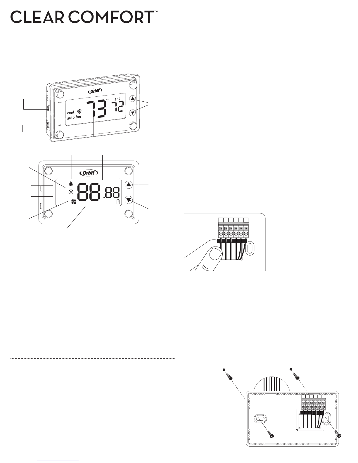
TH ERMOSTATFEATURES
Mode Switch:
Heat/Off/Co ol
Fan Switch:
Auto Fan/Fan On
LCD
Temperature
Adjustment
Buttons
Tips for Thermostat Location
When replacing an existing thermostat, place your new
Clear Comfort™ thermostat in the same location as the old one, unless
the conditions below suggest otherwise. For a new installation, follow
these guidelines for placement:
• Place the thermostat in a room or hallway that is used oen; position on
an inside wall about 5 . (1.52 m) from the floor.
• Avoid installing the thermostat in unusually heated areas (e.g., near a
television, lamp, radiator, or fireplace), in direct sunlight, or on a wall
that has hot water pipes or that is opposite a stove.
• Avoid installing the thermostat in unusually chilled areas, such as in
a dray area (e.g., stairwell, door, or window), on a wall separating an
unheated room, or where air circulation is poor (e.g., in a corner or
behind a door).
• Avoid installing the thermostat in unusually damp areas as this can lead
to corrosion.
• DO NOT install the thermostat until construction work is complete, dust
free, and painting has been completed.
• If the thermostat housing is cold, wait for it to reach room temperature
before installing.
Heat Icon F/C Indicator
Cool Icon
Mode
Indicators
Fan
Indicators
Fan Icon
MODE
heat
off
cool
auto fan
fan on
FAN
Room Temperature
c
set
f
˚
offset
Temperature Offset
Set
Temperature
Low
Battery
Indicator
Room Temperature–Actual temperature of the room
Set Temperature–Desired room temperature
Fahrenheit/Celsius Indicator–
Indicates scale in which temperature is displayed
Mode Indicators–Indicates which mode the system is in: Heat/Off/Cool
Heat Icon–System is in Heating Mode to reach set temperature
Cool Icon–System is in Cooling Mode to reach set temperature
Fan Indicators–Indicates which mode fan is in: Auto Fan/Fan On
Fan Icon–Indicates the fan is energized
Low Baery Indicator–Reminder to change thermostat baeries.
If the baeries are not changed within 7 days aer the Low Baery
Indicator appears on the display, the set temperature will offset by +/- 10°F
as a further reminder. Aer 90 days or less, depending on the condition
of the baeries, the system will turn off and the Low Baery Indicator will
flash on the display.
Temperature Offset–Offset the temperature by +/- 9° F or +/- 4.5° C
SYSTEMTYPE
This thermostat is compatible with 1-stage gas furnaces with electric or gas
fan, 1-stage oil systems, 1-stage heat pumps, and 1-stage cooling systems.
Note: This thermostat is not compatible with base board heaters (or other line
voltage heating), multi-stage heating or cooling systems, or 3-wire hydronic systems
Removing the Old Thermostat from the Wall
WARNING: Switch off electricity to both the heating (furnace) and cooling
(air conditioner) equipment before proceeding with the following steps:
1. Remove the front cover from the old thermostat.
2. Before removing wires from the old thermostat terminals, take note
of the leers printed near each of the wire terminals.
3. Aach a wiring label (included) to its corresponding wire,
so as to identify the wires’ leer; not the wire color.
0/B
G
Y WRCR
Note: While labeling the individual
G
0/B
Y WRCR
wires, DO NOT let the wire fall
back inside the wall, as they can be
difficult to retrieve.
4. Aer labeling the wires, remove them from the old thermostat
terminals (usually by releasing clamps or undoing terminal screws
5. Remove the old base from the wall (usually by removing screws).
Mounting Your Clear Comfort™ Thermostat to the Wall
1. Remove the thermostat body from the base by gently pulling them apart.
2. Place the base flat against the wall by feeding the wires through
the opening below the wiring terminal.
3. Level the base and mark the holes for the mounting screws with a pencil.
4. Remove the base and drill holes at marked positions;
insert the provided wall anchors.
5. Feed wires back through the opening and aach the base to the wall
with the two screws provided.
0/B
Y WRCR
G
INSTALL ATION
Tools required for installation:
• Phillips screwdriver
• Wire cuers/strippers
• Drill with / in. (4.8 mm) drill bit
• Level
0/B
RC
R
Y W
G
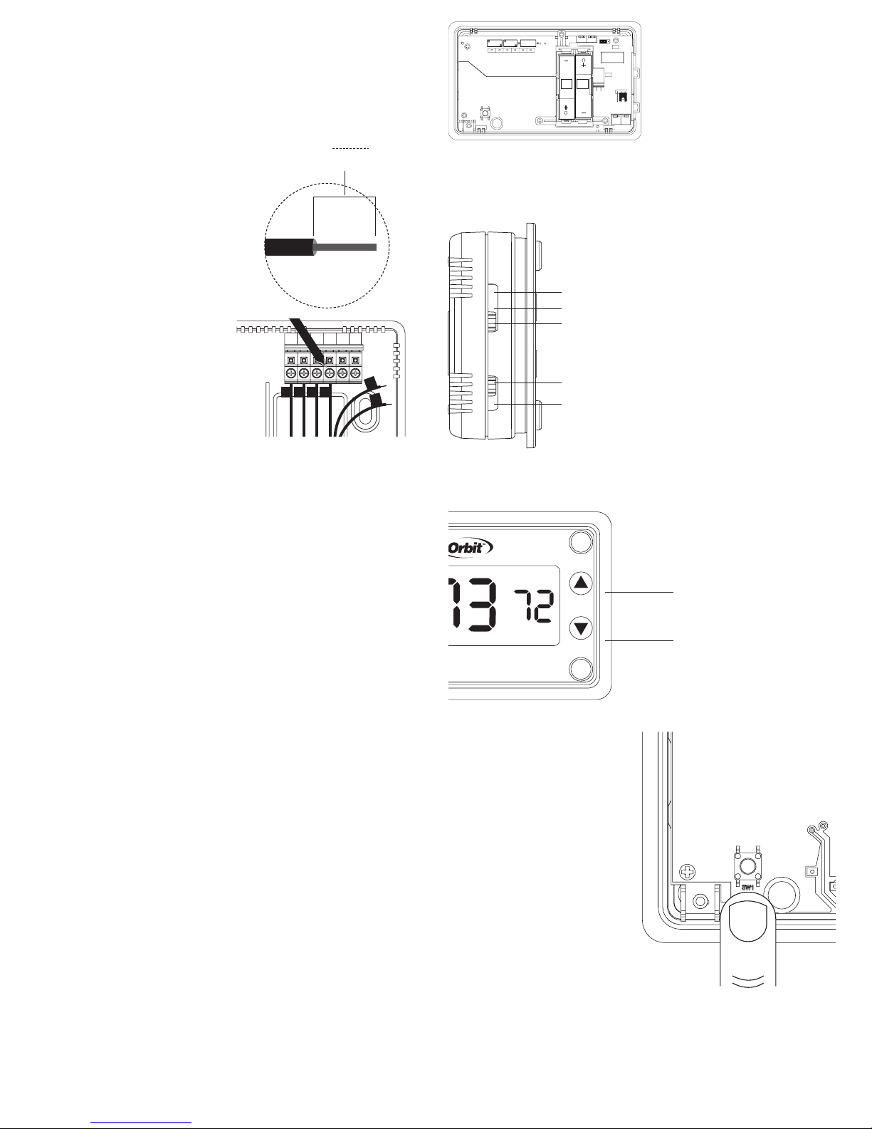
Connecting the Wires to the Terminal
RESET
Arrow down
Arrow up
1. Strip / in. (9.5 mm) insulation from the end of each wire.
2. Loosen the screws on each terminal. Connect each wire to its
appropriate terminal (matching the label on the wire to the label on
the terminal) and tighten the terminal screw to secure the wire.
3. Completely wrap exposed areas of any unused wire with electrical
tape and push them back into the wall hole.
Note: Not having an available wire for
every terminal is normal for some systems.
Note: If you do not have both an R and
RC wire, insert the wire you do have, R
or RC, with the pre-installed jumper wire
(included) that connects the R and RC
terminals. If you have both and R and
RC wire, remove the jumper wire before
connecting the R and RC wires.
Note: Do not let the wires touch each
other or other parts of the thermostat.
Be sure that all wires are routed
through the opening on the thermostat
base, then into the proper terminals.
CAUTION: Stripping too much
insulation from the end of a wire
creates the potential for shorting
between wires and could prevent
proper function of the thermostat.
Note: If installing your Clear Comfort™ thermostat on a heat pump system,
see the "Installation for Heat Pump Systems" section under "Additional
Thermostat Seings." For electric or oil furnaces, see the additional
instructions section under "Fan Jumper."
G
G
0/B
0/B
/ in.
9.5 mm
Y WRCR
Y W
RC
R
Wire/Terminal Identification:
R Connects to Heat/Fan Transformer
RC Connects to Cool Transformer
W Heating Relay—Energized when heating is triggered
Y Cooling Relay—Energized when cooling is triggered
G Fan Relay—Connects to fan and is energized when
either heating or cooling is triggered
O/B Heat pump changeover valve in Cool (O) or Heat (B)
Electric
Gas/Oil
Furnace
601-VO
R RC W Y O/B G C
RESET
SW1
Furnace
AAA
AAA
Heat
Cool
(B)
(0)
Heat Pump
BASICTHERMOSTATOPERATION
Mode Switch: Slide to the appropriate
mode (Heat/Cool) to achieve the set
temperature.
• Heat—System will operate in
Heat
Off
Cool
• Off—System will turn off
• Cool—System will operate in
Fan Switch: Slide to appropriate seing
Auto Fan
Fan On
(Auto Fan/Fan On) to indicate fan
operation.
• Auto Fan—Fan will run automatically
• Fan On—Fan will run continuously
Set Temperature Adjustment: Use Up
and Down Arrow Buons to raise or
lower the set temperature.
• Up Arrow—Raise set temperature
• Down Arrow—Lower set temperature
set
f
˚
Note: If the baeries are not changed
within 7 days aer the Low Baery
Indicator appears on the display, the
set temperature will increase by 10°F
in Cooling Mode, or decrease by 10°F
in Heating Mode as a further reminder.
Aer 90 days or less, depending on
the condition of the baeries, the
system will turn off and the Low Baery
Indicator will flash on the display.
the Heating Mode to reach set
temperature
the Cooling Mode to reach set
temperature
until desired temperature is reached
Up Arrow
Down Arrow
Completing the Installation
1. Insert two Energizer® or Duracell® alkaline AAA baeries (not
included) into the appropriate spaces on the back of the thermostat
body.
2. Verify that the Fan Jumper is in the correct position for your system
type. (See the "Fan Jumper" section under "Additional Thermostat
Seings.")
3. Install the thermostat body by gently pushing it onto the base until it
"clicks" into place. Verify that there are no gaps in the side housing.
4. Switch on the electricity to both the heating (furnace) and cooling (air
conditioner) sources.
Note: Verify that both systems are working properly
by feeling for warm air when the thermostat is in Heat
Mode and cool air when it is in Cool Mode.
Replacing the Baeries
It is recommended that the baeries in the thermostat be replaced once a
year or before leaving the home for a prolonged period of time.
WARNING: Failure to change baeries in a timely fashion can lead to
uncontrolled heating and cooling.
1. Remove the thermostat body from its base by gently pulling them apart.
2. Turn the thermostat over and remove old baeries.
3. Replace them with fresh Energizer® or Duracell® alkaline AAA baeries,
carefully observing the required polarities.
4. Reinstall the thermostat body onto its base by gently pushing it until it
“clicks” into place.
Reset Buon: Use to reset all
system display seings and
temperature gauges back to
factory defaults. (To gain access
Note: Be careful not to touch the
green surface on which the Reset
Buon is mounted, and do not
clean it if dusty.
to the Reset Buon, remove the
thermostat body from its base by
gently pulling them apart.)
• Reset Buon—Press and hold
for five seconds to reset your
thermostat
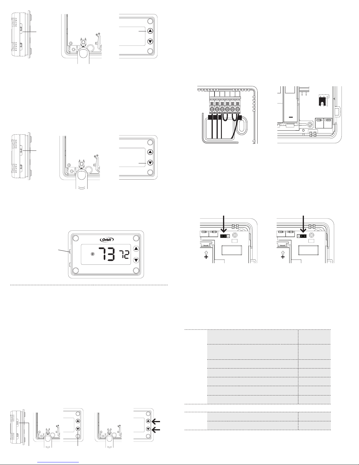
Fahrenheit or Celsius Adjustment:
Set the temperature to read in either °F or °C.
• Slide the Mode Switch to the Off position (Step 1). While holding the
Reset Buon (on the back of the thermostat body), press the Up Arrow
Buon to toggle between °F or °C (Step 2).
RESET
Arrow down
Arrow up
Off
RESET
Arrow down
Arrow up
RESET
Arrow down
Arrow up
0/B
Y R
G
0/B
Y WRCR
G
AAA
AAA
Electric
Furnace
Gas/Oil
Furnace
Heat
(B)
Cool
(0)
Heat Pump
RESET
Arrow down
Arrow up
Up Arrow
Step 1 Step 2
Temperature Offset:
Offset the temperature display to read +/- 9° F or +/- 4.5° C.
• Slide the Mode Switch to the Off position
(Step 1). While holding the Reset Buon (on the back of the thermostat
body), press the Down Arrow Buon until the Offset Indicator appears
(Step 2). Release the Reset Buon. (Do not hold the Reset Buon
for more than five seconds.) Use the Arrow Buons to pick the offset
temperature amount. The thermostat will accept the chosen offset aer
10 seconds of no activity, or by sliding the Mode Switch to Heat or Cool.
Installation for Heat Pump Systems:
If installing your Clear Comfort™ thermostat on a heat pump system,
the following instructions are necessary.
• Insert the additional jumper (included) into the Y and W terminals.
• If a B wire is part of your installation, connect it to the O/B terminal.
Move the jumper located near the right edge on the back of the
thermostat body from the Cool (O) position on the pins to the Heat (B)
position on the pins. If an O wire is part of your installation, connect it to
the O/B terminal. Leave the jumper on the Cool (O) position.
Off
Down Arrow
Step 1 Step 2
Minimum Off Time: To help protect the compressor, the system
will wait five minutes aer turning off before turning on again. The
appropriate Mode Indicator Icon (Heat/Cool) will flash on the display
whenever minimum off time is being enforced.
Icon (snowflake or
flame) flashes while
minimum off time is
being enforced
MODE
cool
auto fan
FAN
set
f
˚
ADDITIONALTHERMOSTATSETTINGS
Seings in this section are not necessary for all systems. These seings,
however, may optimize energy use and comfort levels, especially if a heat
pump system is being used.
System Type Adjustment: Your Clear Comfort™ thermostat is set at
the factory to operate a standard fossil fuel furnace heating system. This
seing can be changed to beer accommodate other heat sources, fan
types or a heat pump system.
• Slide the Mode Switch to the OFF position (Step 1). While holding the
Reset Buon (on the back of the thermostat body), press the Down Arrow
Buon until the Offset Indicator appears (Step 2). Release the Reset
Buon. (Do not hold the Reset Buon for more than five seconds.) Press
the Reset Buon again (Step 3). (The Offset seing will not be lost.) If
using a heat pump, toggle to “HP” using the Up or Down Arrow Buons.
To return to the furnace seing (“F”), press the Up or Down Arrow Buon
(Step 4). The thermostat will accept the seing aer 10 seconds of no
activity, or by sliding the Mode Switch to Heat or Cool.
Step 1 Step 2 Step 3 Step 4
Down ArrowOff
Typical wiring for a heat pump system Jumper position if B wire is connected
Fan Jumper: Correct placement of this jumper optimizes energy use and
comfort levels for the connected system type.
• For electric and heat pump systems, move the jumper located in the topright corner on the back of the thermostat body from the Gas/Oil Heat
position on the pins to the Electric Heat position.
• For gas or oil systems, verify that the jumper is in the Gas/Oil
Heat position.
Electric
Furnace
Gas/Oil
Furnace
Electric
Furnace
Gas/Oil
Furnace
Electric furnace Gas/Oil furnace
Minimum Cycle Period Adjustment:
The cycle period is the minimum time in minutes between each heating or
cooling cycle. As a default, your thermostat’s minimum cycle period is set
to optimize energy use and comfort levels. The default can be changed
based on desired cycle times for specified heat systems.
Recommended Cycle Periods
Sy ste m Type
1-Stage gas furnace heat
with electric fan
1-Stage gas furnace heat
with gas fan
1-Stage oil furnace 12
F
Steam and gravity 60
Hot water system 20
High efficiency furnace 20
Electric furnace
1-Stage heat pump 20
HP
or
Compressor 20
Cycle Period
(Minutes)
12
12
6
 Loading...