

Orbisphere 3600M, 3600, 311 Owner's Manual
3600O2.OM.E9903
3600 Analyzer for Oxygen
Operator’s Manual
Series 3600/3600M Indicating Instrument / Model 311xx Oxygen Sensor
© 1999 Orbisphere. Printed in Switzerland.

2 3600 Analyzer for O2 Measurement—Operator’s Manual
3600O2.OM.E9903
CE conformity
The 3600 / 3600M indicating instrument is manufactured conforming to the requirements of the
electromagnetic compatibility directive: 89 / 336 / CEE
and the low voltage directive: 73 / 23 / CEE
The instrument complies with all the requirements of the following electromagnetic
compatibility standards:
– 3600 instrument:
EN 50081-1 (Jan. 1992), EN 50081-2 (Nov. 1993), and EN 50082-1 (Jan. 1992)
As a result, the 3600 instrument can be used in residential and commercial sites, and for
light industry. It is designed for indoor use in a protected area.
– 3600M instrument:
EN 50081-1 (Jan. 1992), EN 50081-2 (Nov. 1993), and EN 50082-2 (Mar. 1995)
As a result, the 3600M instrument can be used in typical industrial locations.
The 3600 / 3600M instrument satisfies the conditions of the safety standard: EN 61010-1
(1993)
The 3600 / 3600M instrument is developed, manufactured, and inspected by Orbisphere, which
is certified in accordance with the quality standard: ISO 9001 / EN 29001
The tests for safety and for electromagnetic compatibility were performed by the CEM test
laboratory (EMC Fribourg SA, zone industrielle de Montenaz, CH-1728 Rossens) which is
acknowledged by the Swiss Federal Office of Metrology.
Supplementary safety recommendations
For safe operation of the instrument, it is imperative that these service instructions be read and
that the safety recommendations mentioned herein be scrupulously respected.
Opening the instrument exposes non-insulated electrical components with hazardous voltages.
Therefore the instrument should not be opened. If repairs or adjustments are necessary, the
instrument should be returned to an authorized Orbisphere service center.
If these danger warnings are not heeded, serious material or bodily injury could occur.
Dacron, Delrin, Tedlar, Tefzel, and Viton are registered trademarks of DuPont.
Hastelloy is a registered trademark of Haynes International.
Kynar is a registered trademark of The Pennwalt Corporation.
Monel is a registered trademark of IMCO Alloys International, Inc.
Saran is a registered trademark of Dow Chemical Co.
Swagelok is a registered trademark of Swagelok Co.
Microsoft and Windows are registered trademarks of Microsoft Corporation.

3600 Analyzer for O2 Measurement—Operator’s Manual 3
3600O2.OM.E9903
Table of contents
1. Operating Instructions ................................................................................. 5
1.1 What you have received........................................................................................5
1.2 What to check before using the system................................................................6
1.3 Instrument Operation...........................................................................................8
1.3.1 Program Flow Charts...................................................................................................... 9
1.3.2 Oxygen Measurement ................................................................................................... 10
1.3.2.1 Warning Messages.....................................................................................................................11
1.3.3 Calibration Menus ......................................................................................................... 12
1.3.3.1 Instrument Barometric Pressure Calibration..........................................................................12
1.3.3.2 Oxygen Sensor Calibration in Air.............................................................................................12
1.3.3.3 Oxygen Sensor Direct Calibration...........................................................................................14
1.3.3.4 Model 28117 External Pressure Sensor Calibration...............................................................14
1.3.3.5 Model 32646.E Hydrogen Compensation for Oxygen Sensor..............................................16
1.4 Modify Options Menus ........................................................................................17
1.4.1 Display Units................................................................................................................. 18
1.4.2 Thermal Cutoff..............................................................................................................20
1.4.3 Alarm Outputs............................................................................................................... 20
1.4.3.1 Alarms Description...................................................................................................................21
1.4.4 Analog Outputs.............................................................................................................. 21
1.4.4.1 Analog Outputs Description.....................................................................................................22
1.4.5 Serial Output.................................................................................................................24
1.4.6 Salinity and Chlorinity Adjustments................................................................................ 24
1.4.7 H2 Compensation Option (Model 32646.E)................................................................... 25
1.4.8 Self Diagnostics ............................................................................................................. 25
1.4.9 Rolling Average.............................................................................................................. 26
1.4.10 Gas to Measure, CO2/H2S Insensitivity......................................................................... 26
1.4.11 Membrane Selection.................................................................................................... 27
1.5 Maintenance (Sensor Service)............................................................................28
1.5.1 When to Perform a Sensor Service................................................................................28
1.5.2 Remove Sensor from Sample......................................................................................... 28
1.5.3 Prepare Sensor for Cleaning..........................................................................................28
1.5.4 Electrochemical Cleaning...............................................................................................29
1.5.5 Chemical Cleaning......................................................................................................... 29
1.5.5.1 Ammonia Cleaning....................................................................................................................30
1.5.5.2 Nitric acid Cleaning...................................................................................................................30
1.5.6 Polish Sensor Face.........................................................................................................30
1.5.7 Replace Membrane........................................................................................................31
1.5.8 Put Sensor Back into Service..........................................................................................32
1.5.9 Shutting Down the System.............................................................................................32
1.5.10 Troubleshooting.......................................................................................................... 33
1.6 Spare Parts.........................................................................................................34
1.6.1 Oxygen Sensor and Protection Cap Diagram................................................................. 35
1.7 Data Acquisition Software..................................................................................37
1.7.1 Program Setup ..............................................................................................................37
1.7.1.1 Windows 3.1 Setup...................................................................................................................37
1.7.1.2 Windows 95 Setup....................................................................................................................37
1.7.2 Menu Overview.............................................................................................................38
1.7.3 Configuring the Program ............................................................................................... 38
1.7.4 Acquiring Data...............................................................................................................39
1.7.5 Printing, Copying, and Saving Data................................................................................. 40
1.8 Warranty Information.........................................................................................41
1.8.1 About this Manual..........................................................................................................41

4 3600 Analyzer for O2 Measurement—Operator’s Manual
3600O2.OM.E9903
2. Installation Guidelines.................................................................................42
2.1 Instrument Installation .......................................................................................42
2.1.1 Panel or 19-inch Rack Mount Instrument Installation...................................................... 42
2.1.1.1 Instrument Mounting................................................................................................................ 42
2.1.1.2 Power Input.............................................................................................................................. 44
2.1.1.3 Electrical Signal Connections.................................................................................................... 44
2.1.2 Wall Mount Instrument Installation.................................................................................46
2.1.2.1 Instrument Mounting................................................................................................................ 46
2.1.2.2 Power Input.............................................................................................................................. 47
2.1.2.3 Electrical Signal Connections.................................................................................................... 48
2.1.3 Portable Instrument Installation ..................................................................................... 48
2.1.3.1 Instrument Mounting................................................................................................................ 48
2.1.3.2 Power Input.............................................................................................................................. 48
2.1.3.3 Electrical Signal Connections.................................................................................................... 49
2.1.4 Instrument Connectors.................................................................................................. 50
2.1.4.1 Oxygen Sensor Wiring Identification.......................................................................................50
2.1.4.2 External Pressure Sensor Input Wiring Identification.............................................................50
2.1.4.3 RS-232 Wiring Identification....................................................................................................50
2.1.4.4 Recorder Output Wiring Identification................................................................................... 51
2.1.4.5 Alarm Output Wiring Identification......................................................................................... 51
2.1.5 User-supplied Cabling Requirements.............................................................................52
2.1.6 LEMO Connector Assembly Instructions.......................................................................52
2.1.7 Cable Gland Wiring Instructions ....................................................................................52
2.1.8 Instrument Servicing...................................................................................................... 53
2.1.8.1 Battery Replacement (portable instrument)..........................................................................54
2.1.8.2 Analog Current to Voltage Output Conversion.....................................................................54
2.1.8.3 Internal Fuse Replacement....................................................................................................... 54
2.2 Sensor Installation ..............................................................................................55
2.2.1 Model 29501 Sensor Socket Installation ........................................................................ 55
2.2.2 Model 32003 ProAcc Insertion/Extraction Valve Installation .......................................... 56
2.2.3 Model 32001.x Flow Chamber Installation.................................................................... 56
2.2.4 Model 32002.x Multiparameter Flow Chamber Installation........................................... 58
2.2.5 Model 28117 External Pressure Sensor Installation ....................................................... 59
3. Technical Information .................................................................................60
3.1 System Specifications..........................................................................................60
3.2 Principle of Operation.........................................................................................62
Appendix 1—Table of Oxygen Concentrations (ppm)...................................63
Index................................................................................................................69
3600 Analyzer for O2 Measurement—Operator’s Manual 5
3600O2.OM.E9903
1. Operating Instructions
1.1 What you have received
Your 3600 analyzer for oxygen measurements includes two basic components:
• A model 3600/1xx or 3600M/1xx Indicating Instrument, available as a
portable, process (panel or 19-inch rack mount), or wall mount unit; and
• A model 311xx.xx Oxygen Sensor.
These components are available in a variety of configurations, listed in section 3.
Indicating instrument, front panel
The front panel includes a key-lock to switch on the instrument; a two-line liquid
crystal display (LCD), displaying 16 characters across; a “ ” switch to illuminate
the LCD for three minutes when connected to an outside power source; plus four
control keys. Complete operating instructions for this instrument follow—note
that a “Program Flow Chart” in section 1.3.1 gives a handy overview of all onscreen instructions, in the order they appear.
The sensor has a threaded collar and storage cap on top. A plastic screw-on base at
its rear provides a stand for servicing, and protects the screw-on 10-pin LEMO
connection. The sensor cable has a mating LEMO-10 connector.
Oxygen sensor components, plus sensor cable and base—exploded view
A sensor recharge kit, in a blue plastic case, is also included with your shipment.
Inside this kit are the materials to maintain your sensor, such as membranes, a
special membrane mounting tool, polishing powder, and a polishing cloth. The
contents of this recharge kit are listed in section 1.6.
Check to see that any needed mounting hardware has been included. This varies
with each shipment, but in general a flow chamber, multi-parameter flow chamber
(where a model 28117 external pressure sensor also can be mounted), or sensor
socket is usually needed to bring the sensor in contact with the gaseous or liquid
sample. Note that the “Installation Guidelines” in section 2 of this manual include
all the instructions you will need to set up your system. Please refer to this section
now if you are still in the process of configuring your installation.
6 3600 Analyzer for O2 Measurement—Operator’s Manual
3600O2.OM.E9903
1.2 What to check before using the system
Before making initial measurements, first:
Check the voltage and line power—The indicating instrument is available in
115 VAC, 230 VAC, and 10–30 VDC versions. A sticker on the rear panel indicates
which voltage you have. Make sure that it is correct before connecting to a power
supply. Make sure that the ground of the AC supply is connected.
The DC connection must be made by the user, as described in section 2.1.
Note that the portable version can operate without connection to an external
power supply for a period up to 16 hours. If your instrument periodically displays
a “LOW BATTERY” message, it is necessary to recharge the batteries by plugging
the instrument into a power supply and leaving it plugged in overnight.
Check instrument mounting—The instrument is available in portable, process
(panel or 19" rack mount), or wall mount versions. If you are still configuring your
installation, refer to section 2.1 for relevant mounting information.
Check instrument connections—The instrument includes connections for line
power, the oxygen sensor, and an optional external pressure sensor. In addition,
the output pack (optional on portable instruments) includes alarm outputs, analog
current outputs, and an RS-232 serial output. Refer to section 2.1 for complete
wiring and connection information.
Check the oxygen sensor—Shipping conditions can adversely affect Orbisphere
oxygen sensors. You should perform a sensor service as described in section 1.5
before trying to make measurements.
However, if you intend to make trial measurements with the sensor as shipped,
first examine the sensor head. To do this, remove the plastic base at the bottom of
the sensor, then unscrew the calibration cap by loosening its collar.
Your sensor head is fitted with a screw-on protection cap. For a view of the sensor
head, you must remove the cap, using the wrench supplied in your recharge kit.
Do this carefully, making sure not to disturb the membrane that covers the sensor
head, held in place by a membrane holding ring.
O2 sensor components, including exploded view of membrane assembly order

3600 Analyzer for O2 Measurement—Operator’s Manual 7
3600O2.OM.E9903
You should be able now to view the gold cathode, or “working electrode”, in the
center; a guard ring electrode surrounds the cathode, separated by a fine groove.
The anode, or “counter electrode”, is underneath the membrane support. You will
get a better look at all these components during your first sensor service. Before
making a measurement, check the sensor head to see that:
• The membrane holding ring is firmly in place,
• The membrane surface is smooth and wrinkle-free,
• The electrolyte beneath the membrane is free of bubbles,
• The electrodes appear clear, clean, and bright.
Check sensor placement—The oxygen sensor can be placed:
• In a flow chamber (for on-line sampling, that is, samples drawn off line by
6-mm or ¼-inch tubing);
• In a sensor socket or ProAcc insertion/extraction valve for measurements
made directly in a sampling pipe; or
• Directly into “loose” liquid or gas-phase samples.
Check to see that the sensor installation recommendations in the Installation
Guidelines, section 2.2, are followed before proceeding with measurements.
8 3600 Analyzer for O2 Measurement—Operator’s Manual
3600O2.OM.E9903
1.3 Instrument Operation
Once you have reviewed the previous sections of this manual, connect the sensor
to the instrument and turn the keyswitch to the horizontal “on” position. The
system automatically starts in “measurement” mode.
Front Panel Keyswitch
The instrument function keys are active only if the keyswitch is in the horizontal
“on” position. Choose the vertical “locked” position when measuring, to avoid
accidental or unauthorized parameter modification.
Instrument Function Keys
The red “ESC” key lets you jump back a step in the program. Following the flow
chart in section 1.3.1, you will see, for example, if your instrument were displaying
the “Measurement” menu, pressing “ESC” would return you to “Measure
Options Calibrate” (also known as the “main menu”).
MEASURE OPTIONS
CALIBRATE
Use the yellow “ñ” and “ò” arrow keys to scroll through available options at
various stages of operation. Pressing “ñ” moves the “blink” from right to left and
“ò” moves it in the opposite direction. During measurement, use these keys to fix
on a specific displayed measurement range, as described in section 1.3.2.
The red “ENTER” key (“DO” on older instruments) lets you select an item. Note
that when inputting numbers (for example, an alarm limit) the menu displays four
digits, with one digit highlighted by the symbol “^”. This digit is incremented by
pressing “ñ” key and decremented by pressing “ò”. Pressing “ENTER” shifts the
highlight one digit to the right, until last digit, in which case the new whole value is
memorized. (Note that if power is disconnected, the system remembers any values
entered via the “ENTER” key when power is resumed.)
The “ENTER” key also activates a single RS-232 transmission when the
instrument is measuring (and the RS-232 output is in “Manual” mode, as
described in section 1.4.5).
For most installations, calibrating the instrument’s internal atmospheric pressure
sensor and calibrating the O2 sensor in air are necessary first steps. The instrument
is factory calibrated for typical applications. However, it is recommended that you
recalibrate the O2 sensor before making any measurements, using the procedures
described in section 1.3.3.
You may wish to familiarize yourself with the “Modify Options” menus described
in section 1.4. Your instrument is pre-set with certain default values, which enable
you to get started on actual measurements with a newly delivered system, but later
you may need to make other choices of parameters.
3600 Analyzer for O2 Measurement—Operator’s Manual 9
3600O2.OM.E9903
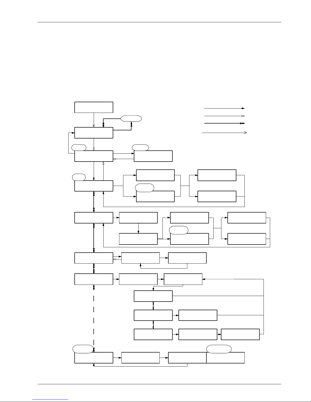
1.3.1 Program Flow Charts
The following flow chart depicts the menus you encounter when the instrument is
first turned on, and an overview of the menu choices. The Measure menu is
described further in section 1.3.2. The Calibration menus depicted below are
described further in section 1.3.3. The Modify Options menus are described in
more detail in section 1.4.
The flow lines are keyed to specific instrument actions. Note that when more than
one item is available within the same menu, the chart uses ellipses (“. . .”) to show
that there are more choices to follow (but you will not see the ellipses on screen).
You may highlight any one of these choices by pressing “ñ” or “ò”.
MEASURE OPTIONS
CALIBRATE
CALIBRATION
IN AIR
(See section 1.6 for
Modify Options menus)
O2 = 7.024 pmv 3
T = 22.3 °C
METHOD
TWO POINTS
V.32603-05.X
18/2/98
Main Menu
CALIBRATION
DIRECT
Calibration
Menu
Change range
CALIBRATION
BAROM. PRESSURE
MODIFY OPTIONS
DISPLAY UNITS
CALIBRATION
EXTERN. PRESSURE
NOW XXX% OF
LAST CALIBRATION
CALIBRATION
OUT OF BOUNDS
CALIBRATION
COMPLETE
NOW XXX% OF
EXPECTED CURRENT
CALIBRATION 0000
CONDITION ^
CC = 8.123 pmv 3
UP/DOWN MODIFIES
NOW XXX% OF
LAST CALIBRATION
CALIBRATION
OUT OF BOUNDS
CALIBRATION
COMPLETE
NOW XXX% OF
EXPECTED CURRENT
PRESSURE
XXXX mbar
BAROMETRIC 0000
PRESSURE ^
after
first calibration
CURRENT
XX.XX nA
EXTERN. PRESSURE
XXXX mbar
LOW POINT 0000
bar ^
CALIBRATION
PURE HYDROGEN
NOW XXX % OF
LAST CALIBRATION
H2 PRESSURE 0000
(CAL) mbar ^
available as
option 32646.E
METHOD
DEFAULT
after
first calibration
METHOD
ONE POINT
Options Menu
ONE POINT 0000
mbar ^
PRESSURE SENSOR
50 psia
HIGH POINT 0000
bar ^
after first calibration
AUTOMATIC (no keystroke required)
ESC
UP/DOWN
ENTER

10 3600 Analyzer for O2 Measurement—Operator’s Manual
3600O2.OM.E9903
1.3.2 Oxygen Measurement
Typical 3600 instruments are delivered with the appropriate measurement and
membrane selections pre-set for your application. However, you can change these
settings if desired. Instructions for the various “options” included are found in
section 1.4, the Modify Options Menu.
The simplest way to check if your system is pre-set for the right measurement
units is to place the system in oxygen measurement mode. Switch on the
instrument (if necessary) to bring up the “Measurement” mode (or select it from
the “Measure Options Calibrate” menu by using the yellow “ñ” or “ò” key if
necessary). You should see a screen like this.
O2 = 00.00 xxx 3
T = 00.0° x ∞
(Note that your system will display actual numerical values in place of the zeros,
and units of measurements for the “x’s” shown here.) If the unit of measurement
on the top line is as expected—for example, in parts per million expressed as
“ppm”—and the appropriate temperature measurement value is expressed (°C,
°K, or °F), then you should be ready to begin to make measurements by placing
your sensor in the sample. (The infinity symbol “∞” only appears as shown when
the system is “busy”, that is, occupied with an internal operation for a few
seconds. Keyboard input will not be accepted during these interruptions.)
Range indication
The range indication appears at the rightmost position of the display’s top line. If
the last position in this line is blank, then you are operating in autoranging mode.
Otherwise, a single digit from 1 to 5 appears, to show which fixed range the
instrument is in. Pressing the “ñ” key will scan this digit upward (“ò” goes
downward) through the permitted “number of ranges” (see section 1.4.1), until it
goes blank, to show that the autoranging mode has been reached. You will also see
the “resolution” of the displayed concentration changing. For example, if you are
configured for three ranges, then you can scan upward through the sequence
...blank-1-2-3-blank... etc. You may see the following message on one or more
fixed ranges (shown here as “Range 3”) during this sequence:
OVERRANGE
RANGE 3
This means that the measured oxygen concentration exceeds the upper limits of
these ranges. Normal corrective action is to press the “ñ” key to reach a less
sensitive range, of which the upper limit exceeds the measured oxygen
concentration. Note that you may see an “Overrange Range 0” message as well.
This is an indication that you are measuring outside the normal limits while in
autoranging mode.
Before making measurements, you should familiarize yourself with the “Modify
Options” menus described in section 1.4. While your instrument is pre-set with
certain default values to anticipate your measurement conditions (for example,
number of ranges, dissolved vs. partial pressure), you may change these for your
application.
What to expect during oxygen measurement
Any sensor previously exposed to the air (or to air-saturated liquid) will, once
placed in a typical sample, generate a signal that decays rapidly at first, then more
slowly as it approaches the actual oxygen level.

3600 Analyzer for O2 Measurement—Operator’s Manual 11
3600O2.OM.E9903
It is normal for the rightmost digits to vary slightly; this is a reaction to slight
variations in oxygen content. However, if drastic changes in temperature occur at
the sensor while in use, correct readings will lag as the sensor adjusts to the new
temperature. The instrument’s response time depends on the membrane used,
anywhere from 7.2 seconds, to 90 seconds, for 90% of total change at 25°C.
(These and other data are found in section 3, “Technical Information”.)
Measurement outputs
The 3600 instrument provides several analog output signals. The analog outputs
represent the measured oxygen concentration, sample temperature, pressure, and
a range indication. These signals are available as 0–5 Volts, 0–20 mA, or 4–20 mA.
You can rescale the oxygen concentration output for your application
requirements. See section 1.4.4 for further description of these analog outputs.
In addition, alarm relay contacts are available in certain 3600 instrument models.
The alarm relays are set in response to various system or measurement conditions.
You can set your own measurement limits—if the measured oxygen concentration
is outside of these limits, the instrument activates the appropriate alarm relay. See
section 1.4.3 for further description of these alarm outputs.
After-use and storage
If you expect not to use your sensor for more than a few months, you should
clean the sensor, as described in section 1.5, and store it “dry”, without electrolyte,
with the storage cap in place for protection.
1.3.2.1 Warning Messages
The following table shows warning messages that appear on the screen in place of
the oxygen concentration, and their explanation.
Message Explanation
CHECK THE SENSOR The sensor is disconnected.
WARNING
THERMAL CUTOFF
The sample temperature exceeds the set upper limit.
See section 1.4.2.
ATTENTION
HIGH LIMIT
The oxygen concentration lies above the high alarm limit. See
section 1.4.3.
ATTENTION
LOW LIMIT
The oxygen concentration lies below the low alarm limit. See
section 1.4.3.
OVERRANGE *
RANGE 1 through 5 (max.)
The oxygen concentration exceeds the upper limit of the
specified measurement range. See section 1.4.1.
OVERRANGE
RANGE 0
The oxygen concentration exceeds the measurement limit while
in “Autoranging” mode. See section 1.4.1.
* If the “OVERRANGE” message appears, it should be sufficient to press the “ñ” key to reach a
less sensitive range. It may also be necessary to enable access to such ranges by pressing “ESC”,
and then raising the “number of ranges” as described in section 1.4.1.
12 3600 Analyzer for O2 Measurement—Operator’s Manual
3600O2.OM.E9903
1.3.3 Calibration Menus
As delivered, 3600 systems are pre-calibrated. However, it is recommended that
you recalibrate the oxygen sensor before making any measurements.
The calibration menu permits the calibration of the oxygen sensor, as well as the
instrument’s internal barometric pressure sensor and an optional external pressure
sensor. The calibration menus are shown in the program flow chart in section
1.3.1.
Note that when you select the calibration menu, the instrument discontinues all
measurement operations.
1.3.3.1 Instrument Barometric Pressure Calibration
The instrument’s atmospheric pressure sensor can be calibrated against your own
barometer.
To calibrate, press “ESC” if necessary to bring up the “Measure Options
Calibrate” screen and highlight “Calibrate”, then press “ENTER”. You will see the
menu below:
CALIBRATION
BAROM. PRESSURE
This menu also includes the options of “In Air”, “Direct”, or “Extern. Pressure”.
Press the “ñ” or “ò” key until “Barom. Pressure” is highlighted, and then press
“ENTER” to see the instrument’s atmospheric pressure measurement:
PRESSURE
980 mbar
If this value (the 980 mbar* value shown is an example only) is acceptable, press
“ESC” to return to the main “Calibration” menu screen. Otherwise, you can
change the value by pressing “ENTER” to bring up this screen:
BAROMETRIC 0000
PRESSURE ^
Use the “ñ” or “ò” key to increment or decrement the each of the four digits, and
press “ENTER” after each digit to move the cursor one place to the right. The
fourth time “ENTER” is pressed, , the instrument stores the value and then returns
to the previous screen. Again, if this is acceptable, press “ESC”. Otherwise, you
may repeat the process by pressing “ENTER” again and re-entering the numbers.
1.3.3.2 Oxygen Sensor Calibration in Air
Once you are satisfied with the barometric pressure indication, the sensor may be
placed in water-saturated air, to provide a known oxygen reference against which
to calibrate. This is done by unscrewing the sensor storage cap, placing the cap
under tap water, then shaking off the water, leaving a few drops inside the cap.
Before replacing the storage cap, note that the screw-on protection cap should be
in place on the sensor head. (If you use a Dacron mesh inside the protection cap,
make sure it is dry before attempting to calibrate.) Then loosely place the storage
cap back on the sensor, holding it in place by a few turns of its collar. The storage
cap and sensor should now be at about the same temperature.
Now turn to the instrument. With the screen displaying
*
Pressure conversion factors are:
1 bar = 1000 mbar = 750.1 Torr or mm Hg = 29.53 inches Hg = 987 atm = 14.5 psi = 100 kPa.
3600 Analyzer for O2 Measurement—Operator’s Manual 13
3600O2.OM.E9903
MEASURE OPTIONS
CALIBRATE
use the “ñ” or “ò” key to highlight “Calibrate”, and then press “ENTER”.
CALIBRATION
IN AIR
To calibrate in air, use the “ñ” or “ò” key to highlight “In Air”, and then press
“ENTER”. This activates the calibration routine.
NOW 95.00% OF
LAST CALIBRATION
The instrument displays the sensitivity of the sensor (that is, the current per unit
partial pressure of oxygen) as a percentage of the sensitivity determined when
calibration was last performed. If, for example, “95% of last calibration” is
displayed, as shown here, then sensitivity has drifted downwards by 5 % since
calibration was last performed. The displayed percentage must be between 30%
and 170% in order to be able to proceed. If this is the case, press “ENTER” to
execute the calibration and display this message briefly . . .
CALIBRATION
COMPLETE
. . . followed by the “Calibration In Air” screen. If you press “ENTER” when the
displayed percentage is outside the permitted range, you will see
CALIBRATION
OUT OF BOUNDS
and you will need to re-examine the sensor for conditions discussed in section 1.2.
In most instances, the sensor will need to be serviced, a procedure described in
section 1.5.
In the program flow chart, section 1.3.1, you will see the note “After first
calibration”. The system considers a “first calibration” to be performed whenever
any particular membrane model is selected by pressing “ENTER” in the “Select
Membrane” menu, or when you have changed any of the options in the “Gas to
Measure” menu. Instead of getting a message on-screen with a percentage of the
“last calibration”, you will see a screen like the following as the system
compensates for the change in parameters;
NOW 95.00% OF
EXPECTED CURRENT
Pressing “ENTER” here will give you either a “Calibration Complete” or
“Calibration out of Bounds” message, as described above.
For reference, a four-page “Table of Oxygen Calibrations” is included in Appendix
1. These tables are useful for verifying your results when have finished sensor
calibration and are back in the “Measurement” mode.
It is possible to receive a “CALIBRATION OUT OF BOUNDS” message even
though you have thoroughly serviced the sensor in accordance with the
procedures in section 1.5. While it is possible that the sensor is in need of repair by
an authorized Orbisphere service representative, it is also possible that the
14 3600 Analyzer for O2 Measurement—Operator’s Manual
3600O2.OM.E9903
instrument simply needs to be reset to its default “Expected Current” after
repeated re-calibrations.
To reset the instrument, enter the “Modify Options/Membrane”, highlight the
membrane model number you are using, and press “ENTER” to “re-select” the
membrane (see also section 1.4.11).
This informs the instrument that it should perform its calibration against expected
current, rather than against the “Last Calibration”. If the sensor is performing
properly, the instrument will accept a new calibration, and you should now receive
a “Calibration Complete” message.
1.3.3.3 Oxygen Sensor Direct Calibration
A “Direct” calibration routine is used when calibrating the oxygen sensor against a
sample of a known oxygen content (that is, a span gas).
(Note that a instrument normally making dissolved oxygen measurements but
calibrated against a gaseous sample using the procedures below will first have to
be configured as a “partial pressure” analyzer, using the “Modify Options” menus
described in section 1.4.1.)
To calibrate, first select the “Calibrate” from the main menu. Press “ñ” or “ò”
until “Direct” is blinking, then press “ENTER”, to bring up this screen:
CALIBRATION 0000
CONDITION ^
Assuming you know the oxygen content to be a certain value, say 8.123 parts per
million of oxygen, you can adjust the value for these four digits with the“ñ” or
“ò” key, and press “ENTER” to activate. This calibration condition screen
(abbreviated “CC”) appears:
CC = 8.123 ppm 3
UP/DOWN MODIFIES
As with instrument menus for alarms and outputs, the unit of measurement and
range are displayed on the top line along with the known value. Pressing
“ENTER” will record this calibration value; the next screen will relate this
calibration to the previous one, as seen before in the “Calibration in Air” menu. As
before, if the value is not within 50 to 150% of the previous calibration, a
“CALIBRATION OUT OF BOUNDS” message prompts you to take corrective
action.
1.3.3.4 Model 28117 External Pressure Sensor Calibration
The 3600 instrument can be fitted with an external pressure sensor, model 28117,
capable of measuring up to 3.5 bar (50 psia). This pressure sensor is mated to the
model 32002 multi parameter flow chamber, as described in the Installation
Guidelines, and interfaces with the instrument via a 4-pin LEMO connector.
If you wish to calibrate your 28117 pressure sensor against a known pressure,
choose “Extern. Pressure” from “Calibration” menu, and press “ENTER” for the
pressure sensor screen.
PRESSURE SENSOR
50 psia
Press “ENTER”, and the instrument now displays what it believes to be the
current external pressure. You can use this as a monitoring screen later:
3600 Analyzer for O2 Measurement—Operator’s Manual 15
3600O2.OM.E9903
EXTERN. PRESSURE
0100 mbar
If this agrees with your current atmospheric reading, then press “ESC” to return to
the menu of interest. However, if you wish to re-calibrate, press “ENTER” to
select the method of calibration.
METHOD
ONE POINT
To calibrate, you have three menu choices:
• “One Point” which permits you to input one pressure value;
• “Two Point” which requires that you calibrate against high and low pressure
values (generally recommended only for high-pressure applications); and
• “Default” which lets the system make its own adjustments.
Use the “ñ” or “ò” buttons to highlight the desired method, and press “ENTER”.
Selecting “Default” causes the instrument to determine the calibration, then return
to the current atmospheric reading display, as shown above.
Activating “One Point” brings up this screen:
ONE POINT 0000
mbar ^
Note that you must enter the absolute (gauge plus atmospheric) pressure. Adjust
each digit with the “ñ” or “ò” key, and press “ENTER” to activate and return to
the “Extern. Pressure” display, as shown above.
The “Two Point” calibration method differs from “One Point” only by requiring
that a “high” and “low” pressure be applied and entered. While this is more time
consuming and is not usually required for precise measurement, it does offer an
additional parameter for the instrument to use for pressure compensations.
LOW POINT 0000
bar ^
The “Two Point” calibration method also requires that you enter the absolute
(gauge plus atmospheric) pressure for each point. Adjust each digit with the “ñ”
or “ò” key, and press “ENTER” to go to the high pressure screen:
HIGH POINT 0000
bar ^
Adjust each digit with the “ñ” or “ò” key, and press “ENTER” to save and return
to the “Extern. Pressure” display, as shown above.
During “Two Point” calibration, error messages are displayed if the sensor voltage
does not fall within a relatively narrow boundary of the expected voltage at both
points. (The possible error messages displayed are: “Pressure points too close”,
“Voltage points too close”, Bad slope”, or “Bad intercept”.) These messages mean
that either the sensor is not functional and should be replaced or repaired, or that
an error has been made in the calibration procedure. If these messages are
displayed, try repeating the two point calibration.
16 3600 Analyzer for O2 Measurement—Operator’s Manual
3600O2.OM.E9903
1.3.3.5 Model 32646.E Hydrogen Compensation for Oxygen Sensor
This software option permits you to operate the O2 sensor in samples containing
high levels of H2. This calibration routine requires that a source of reasonably pure
(for example, 99.8% or better) H2 be available, along with an accurate pressure
gauge. To operate, choose “Pure Hydrogen” from the “Calibration” routine and
then press “ENTER” to bring up this screen:
H2 PRESSURE 1000
(CAL) mbar ^
Using the “ñ” or “ò” key to adjust each digit and “ENTER” to activate, enter the
absolute (gauge plus atmospheric) pressure of the H2 sample (value must not be
zero). The first time this calibration is performed, you will see a menu as follows:
CURRENT
12.34 nA
This is the system’s way of establishing a baseline for the expected sensor current
(in nanoamperes; above is an example only) in the presence of pure H2.
Subsequent calibrations will yield a menu like this:
NOW 95.4% OF
LAST CALIBRATION
Note that in order to use this option, the “H2 Compensation” routine under
“Modify Options” must be enabled. See section 1.4.7.
3600 Analyzer for O2 Measurement—Operator’s Manual 17
3600O2.OM.E9903
1.4 Modify Options Menus
The Options menus include a full set of programmable outputs, plus the ability to
specify different membranes, units of measurement, sample media, and sampling
conditions. The flow chart below gives you a complete screen-by-screen depiction
of the available menus.
WHICH MODE?
MODE 0
LOWEST RANGE
XXXX XXX.X XX.XX
NUMBER OF RANGES
2 3 4 5
TEMPERATURE
°C °F °K
THERMAL CUTOFF
DISABLED ENABLED
GAS MEASUREMENT
PARTIAL PRESSURE
DISSOLVED
ppm ppb:ppm mg/l
MODIFY OPTIONS
DISPLAY UNITS
MODIFY OPTIONS
THERMAL CUTOFF
GAS MEASUREMENT
DISSOLVED
MODIFY OPTIONS
ALARMS
PARTIAL PRESSURE
mbar bar kPa
...X.XXX
...%sat(O2) %sat(air)
mgB mgU
...ppm:% psia Atm
MODIFY OPTIONS
ANALOG OUTPUT
MODIFY OPTIONS
H2 COMPENSATION
MODIFY OPTIONS
SALINITY
MODIFY OPTIONS
SERIAL OUTPUT
WHICH MODE?
MODE 1
OPTIONS
MENU
FRACTION
pmv:%V
THERMAL 0000
CUTOFF ^
CONFIGURE ALARMS
GENERAL
GENERAL ALARM
DISABLED ENABLED
HIGH/HIGH 0000
LIMIT ^
HIGH 0000
LIMIT ^
HH = 43.21 ppm 3
UP/DOWN MODIFIES
H = 1.234 ppm 1
UP/DOWN MODIFIES
AL = 58.76 ppb 1
UP/DOWN MODIFIES
CUSTOM ANALG OUT
DISABLED ENABLED
ANALOG OUT 0000
LOW LEVEL ^
AH = 8.765 ppm 1
UP/DOWN MODIFIES
RS-232
MANUAL AUTO
GAS MEASUREMENT
FRACTION
MODIFY OPTIONS
ROLLING AVERAGE
MODIFY OPTIONS
MEMBRANE
SELECT MEMBRANE
2956 2958 29552
...2952 2995 2935 29521
MODIFY OPTIONS
SELF DIAGNOSTIC
GAS TO MEASURE?
O2
MODIFY OPTIONS
GAS
CO2 INSENSITIVE
NO YES
DIAGNOSTIC TOOLS
SENSOR
DIAGNOSTIC TOOLS
KEYBOARD
available as
option 32646.E
H2 COMPENSATION
DISABLED ENABLED
H2 PRESSURE 0000
(MEAS) mbar ^
DIAGNOSTIC TOOLS
MEMORY
CURRENT
XX.XX nA
PUSH/CONTINUOUS
UP DOWN
PUSH/LATCHED
UP DOWN ENTER
ROLLING AVERAGE
DISABLED 3 5 7 9
H2S INSENSITIVE
NO YES
SAL. CORRECTION
DISABLED ENABLED
SELECT UNITS g/l
CHLORIN. SALIN.
CHLORINITY 0000
MAX 30g/l ^
SALINITY 0000
MAX 54g/l ^
Key to flow lines:
ANALOG OUT 0000
HIGH LEVEL ^
CONFIGURE ALARMS
HIGH/HIGH
HIGH 0000
LIMIT ^
LOW 0000
LIMIT ^
H = 4.321 ppm 3
UP/DOWN MODIFIES
L = 123.4 ppb 1
UP/DOWN MODIFIES
(configuration
download)
CONFIGURE ALARMS
HIGH/LOW
AUTOMATIC
UP/DOWN
ESC
ENTER
YES
NO
18 3600 Analyzer for O2 Measurement—Operator’s Manual
3600O2.OM.E9903
To activate the “Modify Options” menu when your system is in Measurement
mode, press the red “ESC” key to reveal this menu:
MEASURE OPTIONS
CALIBRATE
Using the yellow “ñ” or “ò” arrow keys, highlight “Options” and press
“ENTER” to display the Modify Options menu.
MODIFY OPTIONS
DISPLAY UNITS
The first “Modify Options” screen will depend on which option was last used. For
this manual, we will start with the “Display Units” option.
1.4.1 Display Units
The “Display Units” option allows you to specify whether your oxygen
measurement is for dissolved gas, fraction, or partial pressure; which units of
measurement are to be displayed; the display resolution (decimal placement); the
number of ranges desired; and the temperature units to be displayed.
Below are the standard choices of display units (certain specialized applications
may have additional units available as well):
Dissolved (in water)
ppb:ppm gas concentration in parts per billion or parts per million, by weight *
ppb gas concentration in parts per billion, by weight
ppm gas concentration in parts per million, by weight
mg/l gas concentration in milligrams per liter
%sat(O2) gas concentration in percentage, relative to water saturated in Oxygen
%sat(Air) gas concentration in percentage, relative to water saturated in Air
Partial Pressure
bar gas pressure in bars
mbar gas pressure in millibars
kPa gas pressure in kiloPascals
psia gas pressure in pounds per square inch, absolute pressure
Atm gas pressure in atmospheres
ppm:% gas pressure, relative to calibration pressure, in parts per million or percentage *
Fraction
pmv:%V percentage of gas volume, relative to external pressure sensor (partial pressure /
external pressure), expressed as parts per million or percentage, by volume *
* Composite measurement units—both units are available in autoranging mode; when the
measurement drops below 1.000 of the higher (second listed) units, the measurement is displayed
in the lower (first listed) units.
Under the “Modify Options” menu, highlight “Display Units” using the “ñ” or
“ò” arrow keys, and then press “ENTER” to display this screen:
DISPLAY UNITS
DISSOLVED
You have the choice of “Dissolved”, “Partial Pressure”, or “Fraction” oxygen
measurement. Use the “ñ” or “ò” arrow keys to move the highlight from one
choice to another, and press “ENTER” to select that option.
3600 Analyzer for O2 Measurement—Operator’s Manual 19
3600O2.OM.E9903
For “Dissolved” measurement, the choices are presented as follows:
DISSOLVED
ppb:ppm ppb ppm
The complete list of available units is: ppm, mg/l, % saturation with O2, % sat Air,
and ppb:ppm (plus mg/liter in solvent units “mgU” and “mgB”.) In the ppb:ppm
mode, concentrations below 1 ppm are displayed in ppb (1 ppm = 1000 ppb).
If you are making “Partial Pressure” measurements, this screen appears:
PARTIAL PRESSURE
ppm:% psia Atm
The complete list of available units is mbar, bar, kPa, ppm:%, psia, and Atm. In the
ppm:% mode, concentrations below 1% are displayed in ppm (1% = 10000 ppm).
Please be warned that there is no pressure compensation of partial pressure
measurements. Thus, the ppm:% units are valid only if the total pressure remains
constant at the calibration pressure.
Activating the “Fraction” oxygen measurement brings up this screen:
FRACTION
pmv:%V
Fraction measurement is corrected for external pressure. Thus, you must have the
model 28117 external pressure sensor connected (see the Installation Guidelines,
sections 2.1.4.2 and 2.2.5) and calibrated (see section 1.3.3.4) properly. This unit of
measurement “behaves” identically to other composite units, in that
measurements below 1%V are displayed in parts per million (1%V = 10000 pmv).
Dissolved, Partial Pressure and Fraction menus all proceed to this screen, to
determine display resolution:
LOWEST RANGE
XX.XX XXX.X
You can adjust the placement of the decimal point on the lowest measurement
range to one of the options (X.XXX, XX.XX, XXX.X, or XXXX) by pressing the
arrow keys to highlight your choice; then press “ENTER” to activate. Note that
the units on the “lowest range” will be the most sensitive available. Hence, if
ppb:ppm had been selected, then your selection of lowest range refers to ppb.
Next is the menu for specifying the number of measurement ranges.
NUMBER OF RANGES
2 3 4 5
For example, if you only want measurement values from “XX.XX” to “XXX.X”
with the “XX.XX” value as the “lowest”, you would select “2” from this menu.
You should select 5 ranges for a “composite” unit like ppm:%. In that case, you
could request the 5 ranges: X.XXX, XX.XX, and XXX.X ppm, X.XXX and
XX.XX %.
You can specify temperature units, in the last screen of this routine:
TEMPERATURE
°C °F °K
20 3600 Analyzer for O2 Measurement—Operator’s Manual
3600O2.OM.E9903
1.4.2 Thermal Cutoff
If the sample temperature could exceed the compensated temperature range of the
sensor, you can set an upper temperature limit to automatically cut off the
electrical signal to the sensor to extend the life of the sensor. (As an example, for
steam cycle operation, you may want to set the cutoff for 40.0° C.)
Under the “Modify Options” menu, highlight “Thermal Cutoff” using the “ñ” or
“ò” arrow keys, and then press “ENTER” to display this screen:
THERMAL CUTOFF
DISABLED ENABLED
Highlight “Enabled” to display:
THERMAL 000.0
CUTOFF ^
Note that the menu highlights an individual digit. This means you must press “ñ”
or “ò” to increment or decrement this digit; then press “ENTER” to move to the
next digit. After pressing “ENTER” a fourth time to enter all the digits, the
instrument returns to the “Modify Options” menu. Once this is set, if the sample
temperature exceeds your limit, the outputs drop to their lowest value and a
“WARNING THERMAL CUTOFF” message appears on the display.
1.4.3 Alarm Outputs
The Alarms menus configure the instrument’s internal relays for alarm outputs.
The alarms configuration (High/Low, High/High, or General) determines the
manner in which these relays respond to various conditions. For High/Low and
High/High configurations, separate measurement limits can be set—if the
measured oxygen concentration is outside of these limits the instrument activates
the appropriate alarm relay (see section 1.4.3.1 for description of the alarm relay
responses).
To select the alarms configuration, under the “Modify Options” menu, highlight
“Alarms” using the “ñ” or “ò” arrow keys, and then press “ENTER”:
CONFIGURE ALARMS
HIGH/LOW
This menu also includes the choices “High/High” and “General”. Use the arrow
keys to highlight your choice, and then press “ENTER” to set that configuration.
Note that whenever you select a configuration from this menu, the other two
configurations are cleared from the instrument, and are no longer active.
For the “General” selection, the next menu allows you to enable or disable the
general alarms:
HIGH/LOW ALARM
DISABLED ENABLED
Highlight “Enabled” and press “ENTER” to enable the general alarms, then the
instrument returns to the “Modify Options” menu. (Measurement limit alarms are
not available in this configuration.)
For the “High/Low” selection, you see a menu like the following to set the
measurement limits for this configuration:
HIGH 0000
LIMIT ^

3600 Analyzer for O2 Measurement—Operator’s Manual 21
3600O2.OM.E9903
Use the “ñ” or “ò” arrow keys to increase or decrease the highlighted digits, and
then press “ENTER” to move to the next digit. First, set up all of the significant
digits of the desired limit without regard for the position of the decimal point or
units. Once the fourth digit is set, press “ENTER” to see the following screen:
H = 43.21 ppm 3
UP/DOWN MODIFIES
In this menu, “H” represents the High Limit value. The rightmost digit on the top
line indicates which range is affected: 1 refers to the lowest range, 2 to the second
range, and so on. Use the “ñ” or “ò” keys to modify this setting, and then press
“ENTER” to save your selection.
The instrument then proceeds to the second set of limit menus (Low Limit in our
example; in the last screen, “L” represents the Low Limit). After you enter the
second limit, the instrument returns to the “Modify Options” menu.
For the “High/High” configuration selection, menu operation is as above, except
that the menus use the abbreviations “H” (for High Limit) and “HH” (for HighHigh Limit) in place of the “L” and “H”.
1.4.3.1 Alarms Description
Two alarm relays are provided (“C” and “C1”) in certain instrument models. The
alarms configuration (High/Low, High/High, or General), set using the above
“Alarm Outputs” menus, determines the manner in which the alarm relays
respond to various system or measurement conditions. These alarm conditions
and alarm relay responses are shown in the following table. Note that certain alarm
conditions set both alarm relays.
Configure Condition “C” relay “C1” relay
High/Low No alarm: low limit < O2 concentration < high limit
Low alarm: O2 concentration < low limit
High alarm: high limit < O2 concentration
High/High No alarm: O2 concentration < high limit
High alarm: high limit < O2 conc. < high-high limit
High/High alarm: high-high limit < O2 conc.
General Normal Measurement operation
Overrange, Thermal cutoff, Negative gas signal, Sensor
disconnected, Instrument switched off, or not in
Measurement
Note: This table shows the alarm relay response for the normally open (NO) contacts of each relay
= relay closed, = relay open; the normally closed (NC) contacts are the
reverse state of those shown above.
After a Low, High, or High-High alarm condition is signaled, the instrument clears
the Low alarm when the measured O2 concentration rises to 1% above the low
limit, or clears the High or High-High alarm when the gas concentration drops to
1% below the high or high-high limit respectively.
See section 2.1.4.5 for alarm relay contacts wiring identification.
1.4.4 Analog Outputs
The instrument provides several analog output signals representing sample
measurements (see section 1.4.4.1 for description of these analog outputs). The
Analog Outputs menus scale the O2 concentration output signal between any two
custom concentration limits, for use with external equipment such as recorders.
22 3600 Analyzer for O2 Measurement—Operator’s Manual
3600O2.OM.E9903
Under the “Modify Options” menu, highlight “Analog Output” using the arrow
keys, and then press “ENTER” to display this screen:
CUSTOM ANALG OUT
DISABLED ENABLED
Highlight “Enabled” and press “ENTER” to set your custom analog output levels.
ANALOG OUT 0000
LOW LEVEL ^
Use the “ñ” or “ò” arrow keys to increase or decrease the highlighted digits, and
then press “ENTER” to move to the next digit. First, set up all of the significant
digits without regard for the position of the decimal point or units. Once the fourth
digit is set, press “ENTER” to see the following screen:
AL = 43.21 ppm 3
UP/DOWN MODIFIES
In this menu, “AL” represents the Analog Low Level. The rightmost digit on the
top line indicates which range is affected: 1 refers to the lowest range, 2 to the
second range, and so on. Use “ñ” or “ò” to modify this setting, and then press
“ENTER” to save your selection.
The instrument then proceeds to the Analog High Level menus, similar to the two
above (in the last screen, “AH” is used as the abbreviation). After you enter the
high level, the instrument returns to the “Modify Options” menu.
1.4.4.1 Analog Outputs Description
Four analog outputs are available when the instrument is connected to an external
AC or DC power supply (but not available for battery power). The analog outputs
provide separate signals that represent the measured O2 concentration,
temperature, pressure, and a range indication. These outputs are available as 0–5
Volts, 0–20 mA, or 4–20 mA. See section 2.1.4.4 for analog (recorder) output
wiring connections, and section 2.1.8.2 for current/voltage output conversion.
The analog outputs are generated using a 12-bit digital converter; thus, the
minimum increment of any output can be determined by dividing the output range
by 4096. For example: You could set the gas concentration range to 0–500 ppm for
4–20mA, and your recorder would still pick up changes of 0.2 ppm. The accuracy
of each increment is 1%.
O2 concentration (gas) output
You can scale the analog output signal representing sample O2 concentration
between any two gas concentration levels, “AL” and “AH” (see menus above).
The default values of these levels are 0 and 9999, respectively. When “Custom
Analog Output” is enabled (with the “Analog Output” menus above), the AL and
AH levels can be set as desired.
The relation between the analog output current “I” (in mA) or voltage “V”, and
the gas concentration “C” is as follows, as scaled by these limits:
0–20 mA C = AL + (AH - AL) * I/20
4–20 mA C = AL + (AH - AL) * (I - 4)/16
0–5 Volts C = AL + (AH - AL) * V/5
 Loading...