

Page 1
CANADA
CANADACANADA
CANADA
,
, ,
,
USA
USAUSA
USA
, BRAZIL,
, BRAZIL, , BRAZIL,
, BRAZIL,
CHILE,
CHILE, CHILE,
CHILE,
SPAIN,
SPAIN, SPAIN,
SPAIN,
UK
UKUK
UK
,
, ,
,
FRANCE
FRANCEFRANCE
FRANCE
,
, ,
,
GERMANY
GERMANYGERMANY
GERMANY
,
, ,
,
INDIA
INDIAINDIA
INDIA
,
, ,
,
CHINA
CHINACHINA
CHINA
,
, ,
,
SOUTH EAST ASIA
SOUTH EAST ASIASOUTH EAST ASIA
SOUTH EAST ASIA
www.orbinox.com
www.orbinox.comwww.orbinox.com
www.orbinox.com
INSTALLATION, OPERATION &
MAINTENANCE MANUAL
MODEL BR
Page 2
.
EDITION 01-2016
BR-2/10
www.orbinox.com
MODEL
BR
INDEX
INDEXINDEX
INDEX Page
0.- Description .........................…………………………………..……................................. 2
1.- Handling ..................................………..............................…………………………….. 2
2.- Installation .................................………..................................................................... 4
3.- Actuators .....................................………................................................................... 6
4.- Maintenance .....................................……….............................................................. 6
4.1.- Gland packing replacement and sleeve …….………................................... 7
4.2.- Lubrication ......………………...…....…….................................................... 8
5.- Storage …………................................…..………....................................................... 9
6.- Parts list & drawing ..................................……………………………………..…......... 10
0.- DESCRIPTION
The BR model knife gate is a bi-directional valve and consequently it can be installed without
considering the flow direction.
This valve is designed for general industrial service applications. The design of the body and seat
assures non-clogging shut-off with suspended solids.
The BR valve complies with the following European directives:
- DIR
DIR DIR
DIR 2006
20062006
2006////42
4242
42/EC (machines)
/EC (machines)/EC (machines)
/EC (machines)
- DIR 97/23/EC (PED)
DIR 97/23/EC (PED)DIR 97/23/EC (PED)
DIR 97/23/EC (PED) Fluid: Group 1 (b), 2 (Cat. I, mod.A)
It may also comply with the directive:
DIR 94/9/EC (Explosive Atmospheres)
DIR 94/9/EC (Explosive Atmospheres)DIR 94/9/EC (Explosive Atmospheres)
DIR 94/9/EC (Explosive Atmospheres)
The BR valve may comply with the directive regarding equipment and protective systems for their
use in explosive atmospheres. In these cases, the logotype shall appear on the identification
label of the valve. This label shows the exact classification of the zone where the valve can be
used. The user will be liable for its use in any other zone.
This directive only applies in the following atmospheric conditions:
0,8 bar ≤ P ≤ 1,2 bar
-20ºC/-4Fº < T < 60ºC/140Fº
Any increase in temperature due to frictional warmth is negligible, since the relative speed of
the moving parts is extremely low.
The risk analysis associated to this directive does not take into account the fluid that goes
through the valve, even when such fluid produces an explosive atmosphere. The user must take
into account the risks that the fluid generates, such as:
- heating of the valve surface.
- generation of electrostatic charges caused by displacement of the fluid.
- shock waves caused by the installation (water hammer), internal crashes generated by the
pellets or the risks due to foreign bodies susceptible of being present in the installation.
1.- HANDLING
The valves are packed according to the appropriate transport standards. If you receive a shipment with
damaged packaging, please inform the transport company in writing and contact your Orbinox
representative.
Page 3
.
EDITION 01-2016
BR-3/10
www.orbinox.com
MODEL
BR
When handling an Orbinox valve please pay attention to the following points:
• Do NOT attac
Do NOT attacDo NOT attac
Do NOT attach lifting gear to the valve actuators or gate guards
h lifting gear to the valve actuators or gate guardsh lifting gear to the valve actuators or gate guards
h lifting gear to the valve actuators or gate guards. They are not designed to
bear the weight, and could easily be damaged.
• Do NOT lift the valve by the valve bore
Do NOT lift the valve by the valve boreDo NOT lift the valve by the valve bore
Do NOT lift the valve by the valve bore.
This can cause damage to the seating surfaces and seals.
• Check that selected lifting gear is rated to carry the weight of the valve.
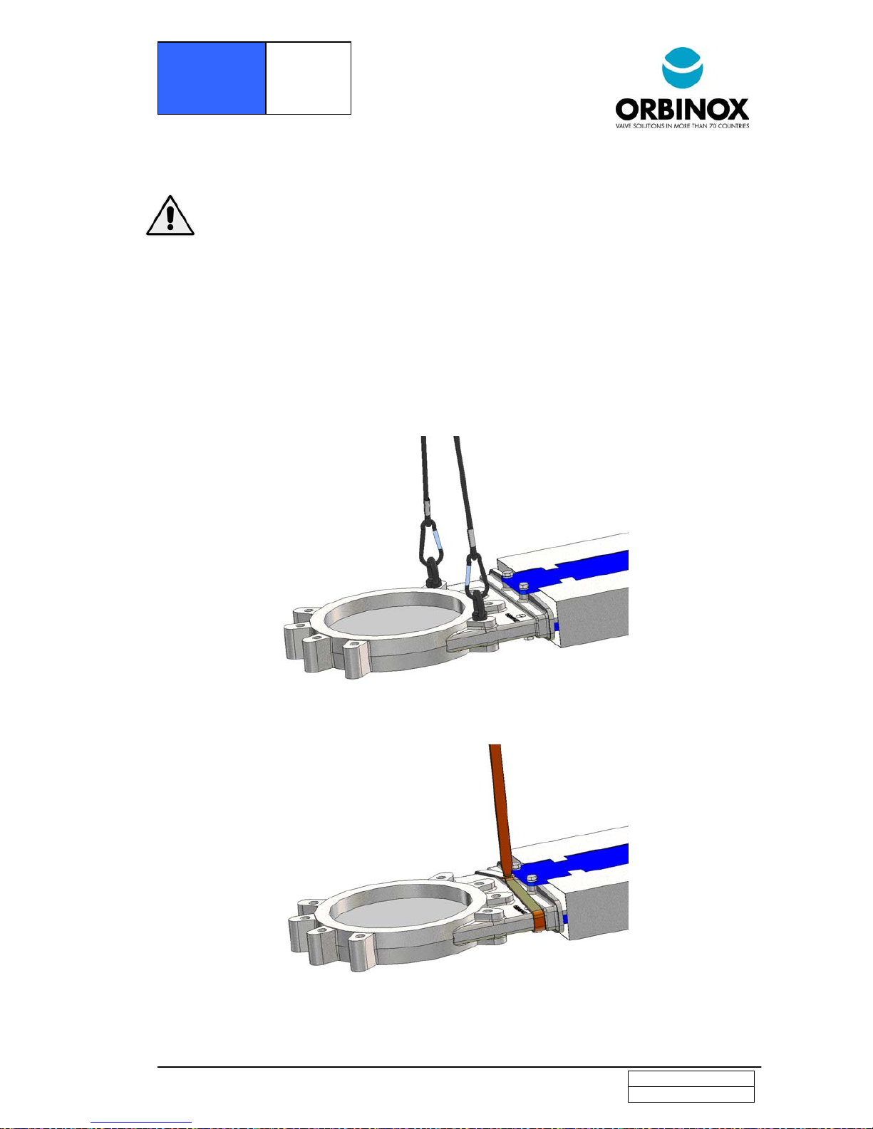
• The valve can be handled using eyebolts, soft straps or slings.
• Eyebolts: make sure the eyebolts have the same thread as the boltholes and they are all well
secured. Ideally when using lifting gear to move an Orbinox valve, it should be supported by
two or more eyebolts screwed into the tapped fixing holes in the valve body.
• Soft straps: with the valve in the closed position, the straps should be placed between the
gland area and the bore such that the valve is balanced.
Fig. 1 Handling with eyebolts
Fig. 1 Handling with eyeboltsFig. 1 Handling with eyebolts
Fig. 1 Handling with eyebolts
Fig. 2 Handling with soft straps
Fig. 2 Handling with soft strapsFig. 2 Handling with soft straps
Fig. 2 Handling with soft straps
Page 4
.
EDITION 01-2016
BR-4/10
www.orbinox.com
MODEL
BR
2.- INSTALLATION
To avoid personal injury or damage to property from the release of process fluid:
• Those in charge of handling and maintenance of the valve must be qualified and trained in
valve operations.
• Use appropriate personal protection equipment (gloves, safety shoes, etc).
• Shut off all operating lines to the valve and place a warning sign.
• Isolate the valve completely from the process.
• Release process pressure.
• Drain the process fluid from the valve.
• According to EN 13463
EN 13463EN 13463
EN 13463----1 (15),
1 (15), 1 (15),
1 (15), during installation and maintenance operations, use hand
tools (non electric)
(non electric) (non electric)
(non electric) with Working Allowance.
Before installation, inspect the valve body and components for any damage that may have occurred
during shipping or storage. Make sure the internal cavities within the valve body are clean. Inspect the
pipeline and mating flanges, making sure the pipe is free of foreign material and that the flanges are
clean.
Note that these bi-directional knife gate valves are not suitable for dead-end service without a
slight modification or a counter flange, please consult factory.
Special care should be taken to maintain the correct distance between the flanges and to ensure that
they are parallel to the valve body. Incorrect alignment of the valve can cause deformations, which can
lead to difficulties in operation.
The following table gives the maximum torque values for the valve installation bolts. Also shown
is the maximum depth (T) allowed for the tapped blind boltholes drilled into the valve body.
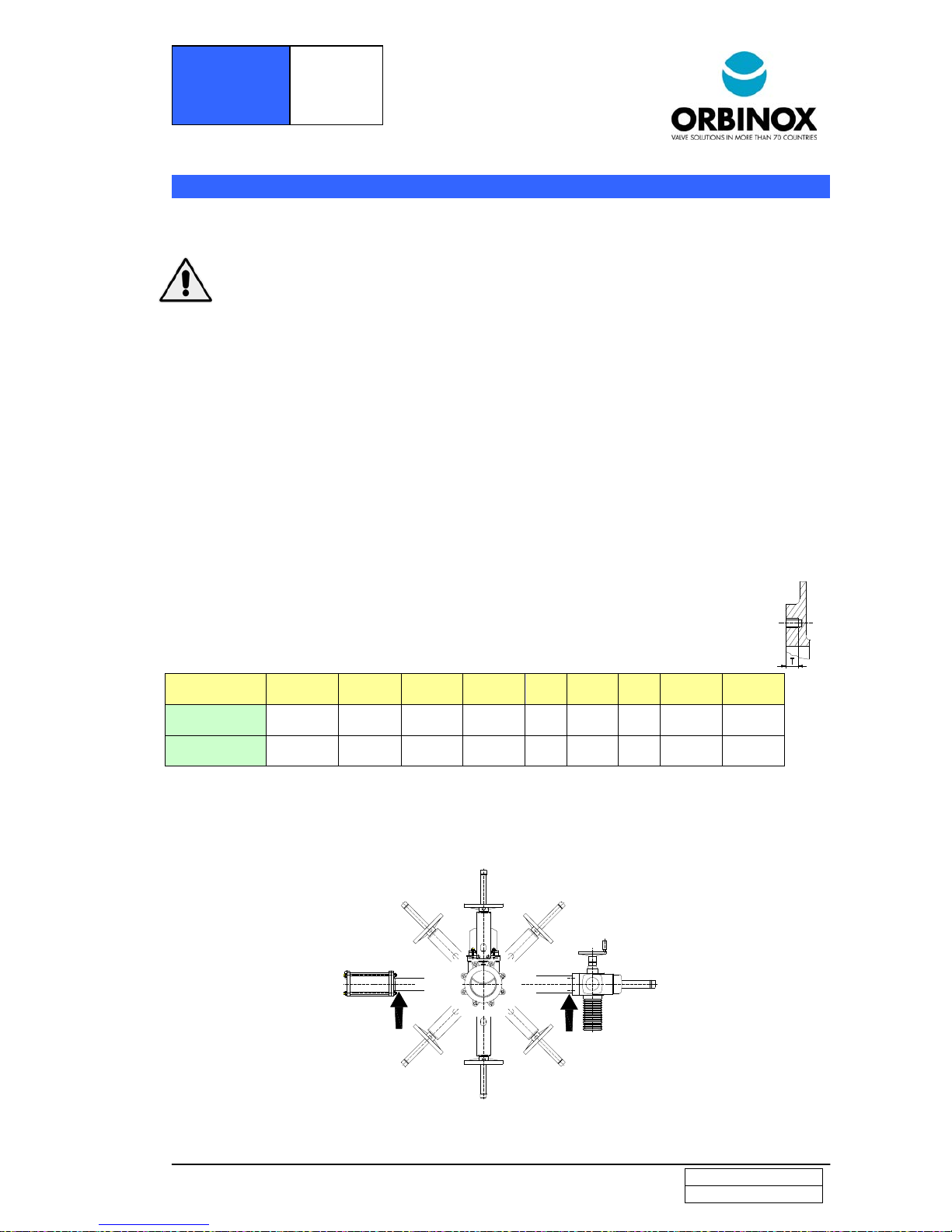
With heavy actuators (pneumatic, electric, etc.), with the valve installed horizontally (B) or at an angle
(C) on a horizontal pipeline, the installation might require the construction of suitable supports. (See the
following diagram and consult the technical department Orbinox)
.
B
B
A
CC
C*
A*
C*
* These positions are not recommended.
DN
DNDN
DN
2”
50
2,5”
65
3”
80
4”
100
5”
125
6”
150
8”
200
10”
250
12”
300
T (inch
)
(mm)
11/32”
11
11/32”
11
11/32”
11
11/32”
11
3/8”
14
3/8”
14
3/8”
14
18/32”
18
18/32”
18
Kg.m
lbf x ft
6
43
6
43
6
43
6
43
7
50
7
50
7
50
11
80
11
80
Page 5
.
EDITION 01-2016
BR-5/10
www.orbinox.com
MODEL
BR
Once the valve is installed, test that the flanges have been fastened correctly and that all electrical
and/or pneumatic connections have been properly made.
These instructions must be observed when installing an Orbinox knife gate valve in an ATEX zone:
• Make sure the valve is ATEX marked according to the requested zone and it includes all
anti-static devices.
• Check continuity between the body of the valve and the pipe (test in accordance with EN
12266-2 Standard, annex B, points B.2.2.2. and B.2.3.1).
• This check must be done every time the valve has been removed from the line, serviced,
and put back to the line.
The operation of automated valves requires fitted gate covers (optional in some countries).
First, operate the valve with no flow in the pipeline. Then test operation and valve seal with flow. It
should be noted that the packing material might settle in shipping/storage, which can cause minor
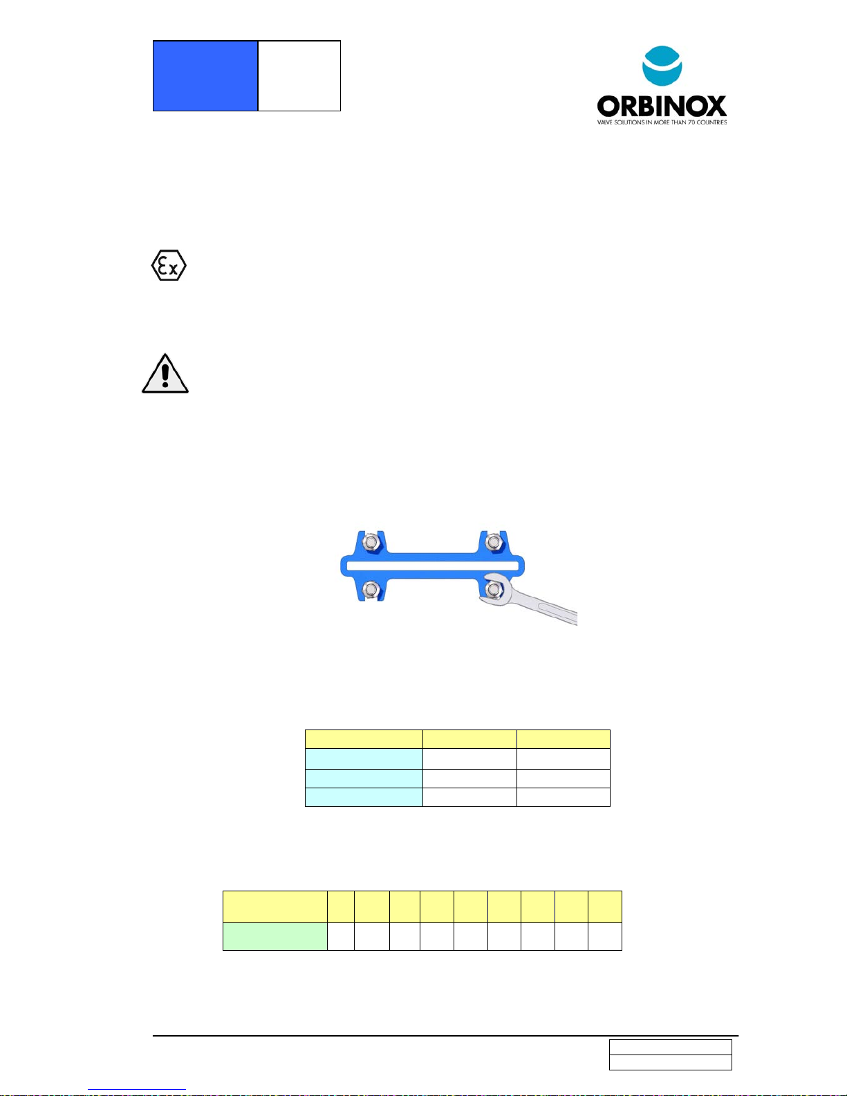
leakage. This can be remedied by tightening the gland follower (6) during installation. The nuts shall be
tightened gradually and crosswise until the leakage stops (see the next figure). Check that there is no
metal contact between the gland follower (6) and the gate (2).
If the gland follower nuts are over-tigtened, the force needed to operate the valve will increase, the
valve function will be affected and the packing lifespan will be shortened.
The table below shows the maximum torque value for tightening the gland follower nuts.
DN (inch/mm)
DN (inch/mm)DN (inch/mm)
DN (inch/mm) Torque (N.m)
Torque (N.m)Torque (N.m)
Torque (N.m)
Lbsf x ft
Lbsf x ftLbsf x ft
Lbsf x ft
2”/50 – 4”/100 20
144
5”/125 – 8”/200 30
216
10”/250 – 12”/300 35
263
Once performance has been tested, the valve can be put into operation.
Approximate weight of the handwheel-operated valves (rising stem):
DN
DNDN
DN
(inch)
(inch)(inch)
(inch)
(mm)
(mm)(mm)
(mm)
2”
50
2,5”
65
3”
80
4”
100
5”
125
6”
150
8”
200
10”
250
12”
300
Weight
WeightWeight
Weight
(lbs
(lbs(lbs
(lbs
))))
(kg)
(kg)(kg)
(kg)
15
7 17
8 20
9 24
11
33
15
40
18
66
30
97
44
127
58
Page 6
.
EDITION 01-2016
BR-6/10
www.orbinox.com
MODEL
BR
3.- ACTUATORS
3.1.- Handwheel
To open the valve turn the handwheel (14) counter clockwise. To close turn the handwheel
clockwise.
3.2.- Pneumatic
Valves are usually supplied with a double acting pneumatic actuator although, upon request,
we can supply single-acting actuators. In either case the air supply pressure can vary between
55psi/3,5 Kg/cm2 and 150psi/10 Kg/cm2. However, the size of the actuator for each valve
has been designed for an air supply pressure of 90psi/6 Kg/cm2.
It is essential for a good maintenance of the cylinder that air should be well dried, filtered and
lubricated.
It is recommended to actuate the cylinder 3-4 times before the start up, once it is installed in the
pipeline.
Air quality requirements according to ISO 8573-1 Grade 5:4:3 for normal processes, Grade
5:3:3 for cold temperature applications (min. -20º C water dew point); for cylinders with
positioners Grades 3:4:3 (standard) / 3:3:3 (-20ºC).
3.3.- Electric actuator
Depending on the type or make of the electric actuator, specific instructions (i.e. a
manufacturer’s manual) will be supplied.
• Allowed actuators for ATEX zones: Hand wheel, Chain Wheel, Bevel Gear, Lever,
Pneumatic Actuator (double acting ONLY
ONLYONLY
ONLY) and Electric Motor
• Make sure these actuators are ATEX marked according to the requested zone.
• Maximum travel speed of the gate must equal or below 0,05 m/s
4.- MAINTENANCE
The valve must not undergo any modifications without a previous agreement with ORBINOX.
ORBINOX shall not be liable for any damages that may arise due to the use of non original parts or
components.
To avoid personal injury or damage to property from the release of process fluid:
• Those in charge of handling and maintenance of the valve must be qualified and trained in
valve operations.
• Use appropriate personal protection equipment (gloves, safety shoes, etc).
• Shut off all operating lines to the valve and place a warning sign.
• Isolate the valve completely from the process.
• Release process pressure.
• Drain the process fluid from the valve.
• According to EN 13463
EN 13463EN 13463
EN 13463----1 (15),
1 (15), 1 (15),
1 (15), during installation and maintenance operations, use hand
tools (non electric)
(non electric) (non electric)
(non electric) with Working Allowance.
The only maintenance required is to change the gland packing (5) or the sleeve (3).
The life of these elements will depend on the working conditions of the valve such as: pressure,
temperature, abrasion, chemical action, number of operations, etc.
To change the sleeve, remove the valve from the line.
Page 7
.
EDITION 01-2016
BR-7/10
www.orbinox.com
MODEL
BR
4.1.
4.1. 4.1.
4.1. ---- Replacement of the gland packing (
Replacement of the gland packing (Replacement of the gland packing (
Replacement of the gland packing (5555) and the s
) and the s) and the s
) and the sleeve
leeveleeve
leeve (3)
(3)(3)
(3)::::
1. Depressurise the circuit and place the valve in close position.
2. Remove the gate guards (for automated valves only).
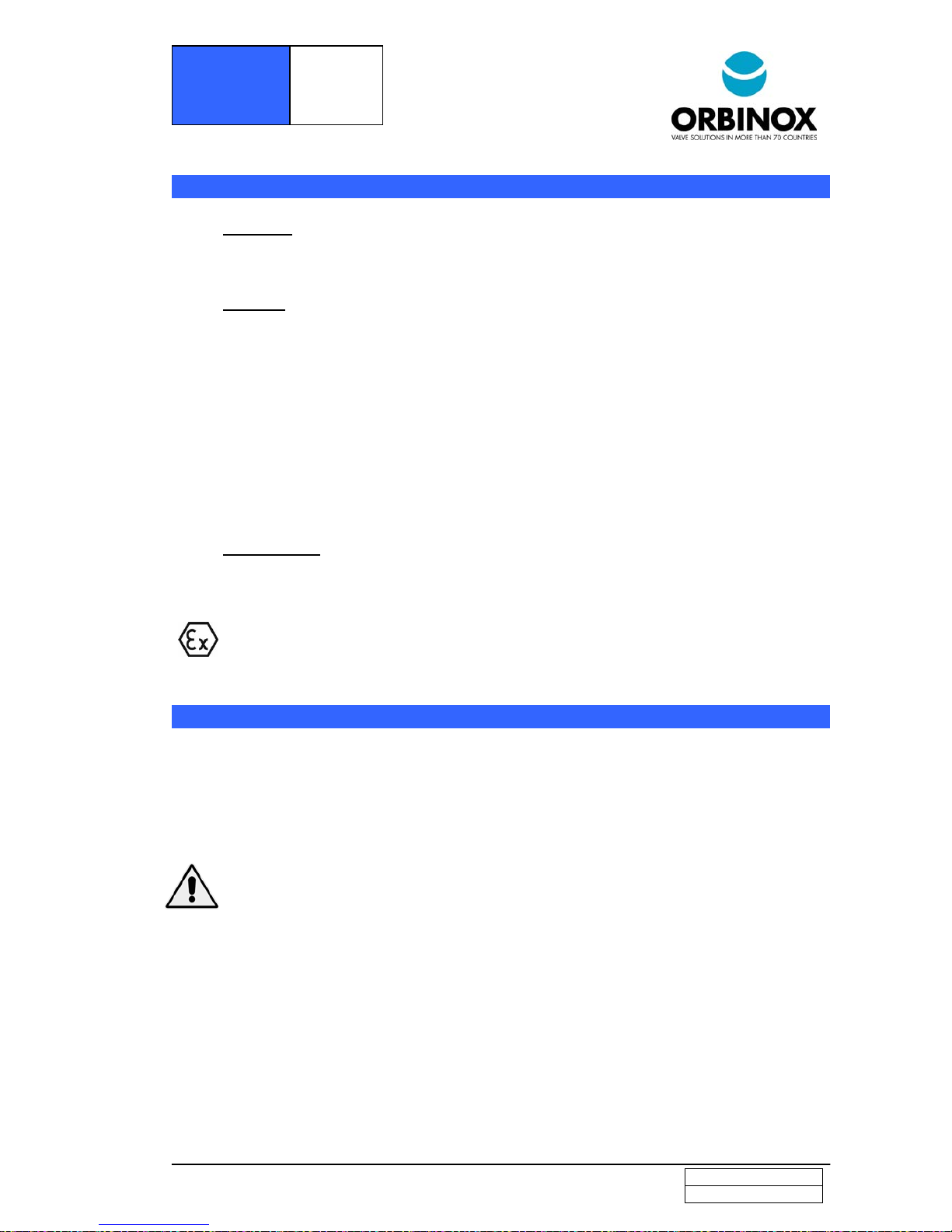
3. Non rising stem valves. Photo1: Release the stem nut (8) from the gate (2). Rising stem valves,
Photo 2: Release the spindle or stem (7) from the gate (2).
Photo 1 Photo 2
4. Loosen the screws of the yoke (9) and remove it (without loosing the actuator).
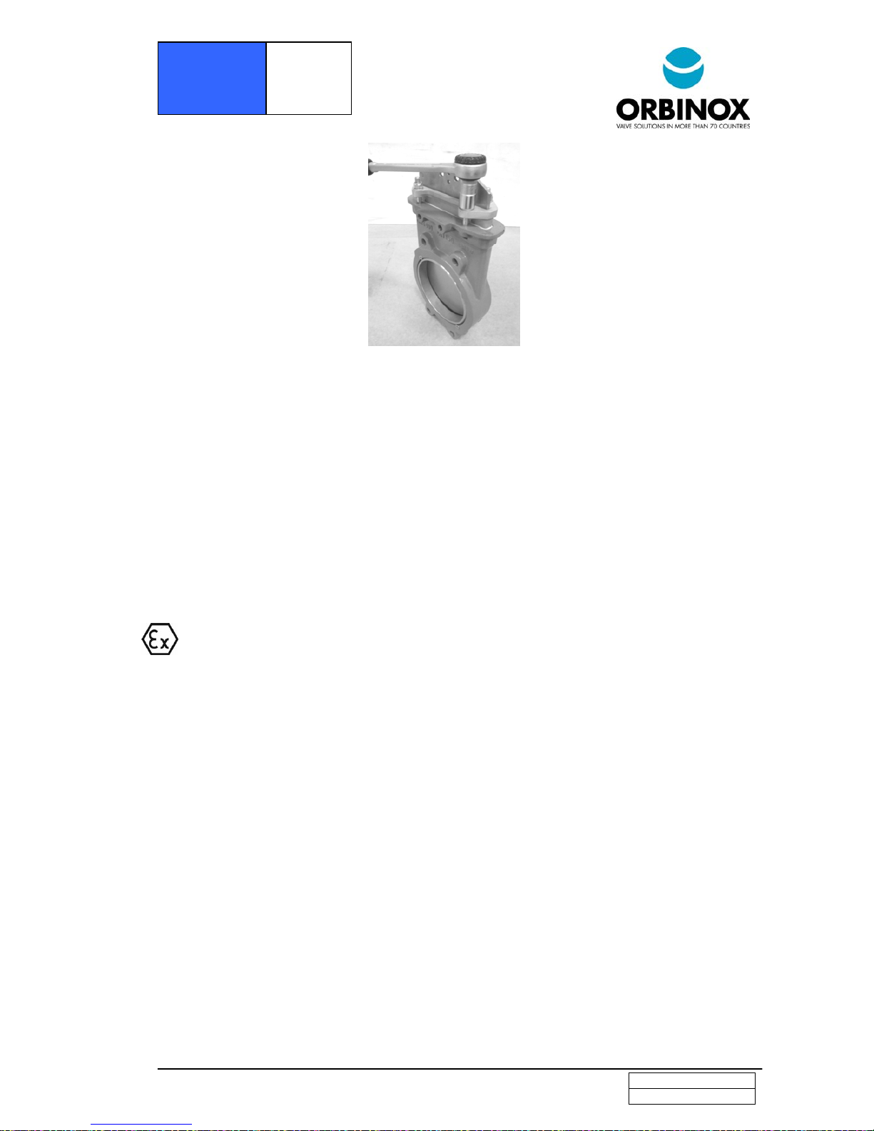
5. Loosen the nuts of the gland follower (6) and remove it. (Photo 5)
6. Remove the old packing rows (5), gate (2), 2 seat rings (4) and the old sleeve (3). Clean the
stuffing box area.
7. In order to have the sleeve correctly positioned, have the new sleeve (3) greased and insert it in
the body (1) cavity.
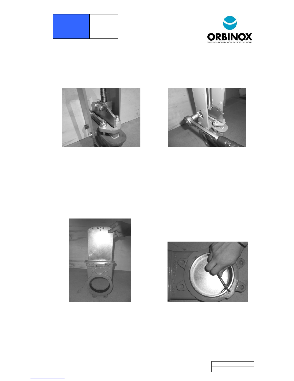
8. Introduce the gate (2) completely until the sleeve is totally centered. (Photo 3)
9. Fix the 2 seat rings (4) and secure them by means of two bolts. (Photo 4)
Photo 3 Photo 4
10. Once the necessary new rows of packing (5) have been inserted, proceed with a steady initial
tightening of the gland follower (6). (Photo 5)
Page 8
.
EDITION 01-2016
BR-8/10
www.orbinox.com
MODEL
BR
Photo 5
11. Reinstall the yoke (9) (with the actuator) and tighten it.
12. Reinstall the stem nut (8) to the gate (2) (Non rising stem valves. Photo 1) or reinstall the stem
(7) to the gate (2)( Rising stem valves. Photo 2).
13. Reinstall the gate guards (for automated valves only).
14. Carry out some operations with a loaded circuit and then re-tighten the gland follower (6) to
stop any leakage.
4.2.
4.2. 4.2.
4.2. ---- Lubrication:
Lubrication:Lubrication:
Lubrication:
Lubricate the stem every 30 days with a calcium-based grease with the following characteristics: highly
water resistant, low ash content, and excellent adherence.
Special requirements for ATEX valves
Special requirements for ATEX valvesSpecial requirements for ATEX valves
Special requirements for ATEX valves:
• The maintenance personnel must be made fully aware of the risks of explosion, and it is
advisable that they receive specific training regarding ATEX.
• Periodicity of check and evaluation of graphite packing status and valve electrical conductivity
must be determined by end user according to valve working conditions. In any case, once the
valve is put into operation, the packing area must be revised after the valve has been stroked
100 times or after 3 months of operation, whichever occurs first. After this preliminary
inspection, new inspection and schedule must be determined by end user based on the results of
this first inspection.
• Clean the valve periodically to prevent dust accumulation. Do not sweep or dump the dust.
Always use a vacuum cleaner system
• Dead en service is not allowed.
• Do not apply any new coating to the valve. Should it require new coating, please contact our
closest representative.
• Allowed sleeves: EPDM, FKM-FPM and NITRILE.
• Allowed packing: ST
• Any other materials but those above are not allowed to be used in ATEX zones.
• In order to keep the ATEX approval, always use original spares from Orbinox.
Washer DIN 6798A (This washer guarantees continuity among carbon steel parts, coated
in epoxy, yoke and body and stainless steel guards for coating thicknesses up to 200 microns)
ST packing ORBINOX ST: Synthetic packing impregnated with PTFE
• After any maintenance of ATEX valves, it is mandatory to check that the valve is grounded
through the pipe, and there is continuity among the different valve components, such as the
body, the gate, the supports, and guards (test in accordance with EN 12266-2 Standard, annex
B, points B.2.2.2. and B.2.3.1).
Page 9

.
EDITION 01-2016
BR-9/10
www.orbinox.com
MODEL
BR
MAXIMUM FLUID TEMPERATURES
MAXIMUM FLUID TEMPERATURESMAXIMUM FLUID TEMPERATURES
MAXIMUM FLUID TEMPERATURES
Atmosphere
AtmosphereAtmosphere
Atmosphere
Gas/air, steam/air, and mist/air
Gas/air, steam/air, and mist/airGas/air, steam/air, and mist/air
Gas/air, steam/air, and mist/air Dust/air
Dust/airDust/air
Dust/air
80% of minimum fluid ignition
temperature, minus 10ºK
2/3 of minimum dust cloud ignition
temperature minus 85ºK
Note: these maximum fluid temperatures apply to all categories. The differences between categories are
the consideration of foreseeable malfunction cases and rare malfunctions cases
MAXIMUM
MAXIMUM MAXIMUM
MAXIMUM SSSSLEEVE
LEEVELEEVE
LEEVE AND PACKING
AND PACKINGAND PACKING
AND PACKING TEMPERATURES
TEMPERATURESTEMPERATURES
TEMPERATURES
Max Temperature
Max Temperature Max Temperature
Max Temperature
((((ºC)
C)C)
C)
(F
(F(F
(Fº))))
SLEEVE
SLEEVESLEEVE
SLEEVE
EPDM
EPDM EPDM
EPDM FKM
FKMFKM
FKM----FPM
FPMFPM
FPM NITRILE
NITRILE NITRILE
NITRILE
120
248
200
392
120
248
Max Temperature
Max TemperatureMax Temperature
Max Temperature
((((ºC)
C)C)
C)
(F
(F(F
(Fº))))
PACKING
PACKINGPACKING
PACKING
ST
ST ST
ST
240
464
Note: Most of the time the sleeve´s maximum temperature capacity is the key limitation factor when
evaluating valve maximum working temperatures. In ATEX zones these temperatures must be compared
to those above related to limitation of fluids temperatures. Always consider the most restrictive as
maximum valve working temperature.
5.- STORAGE
• For long storage periods keep the valves indoors in a safe and dry place and protect it from any
impact and or vibrations.
• Storage temperatures: -10ºC/ 14ºF to +40ºC/104ºF
• Valves must be stored in either full open or full closed position.
• For any component installed on the valves, electric motors, solenoid valves, etc, please refer to their
own instruction manuals
Page 10
.
EDITION 01-2016
BR-10/10
www.orbinox.com
MODEL
BR
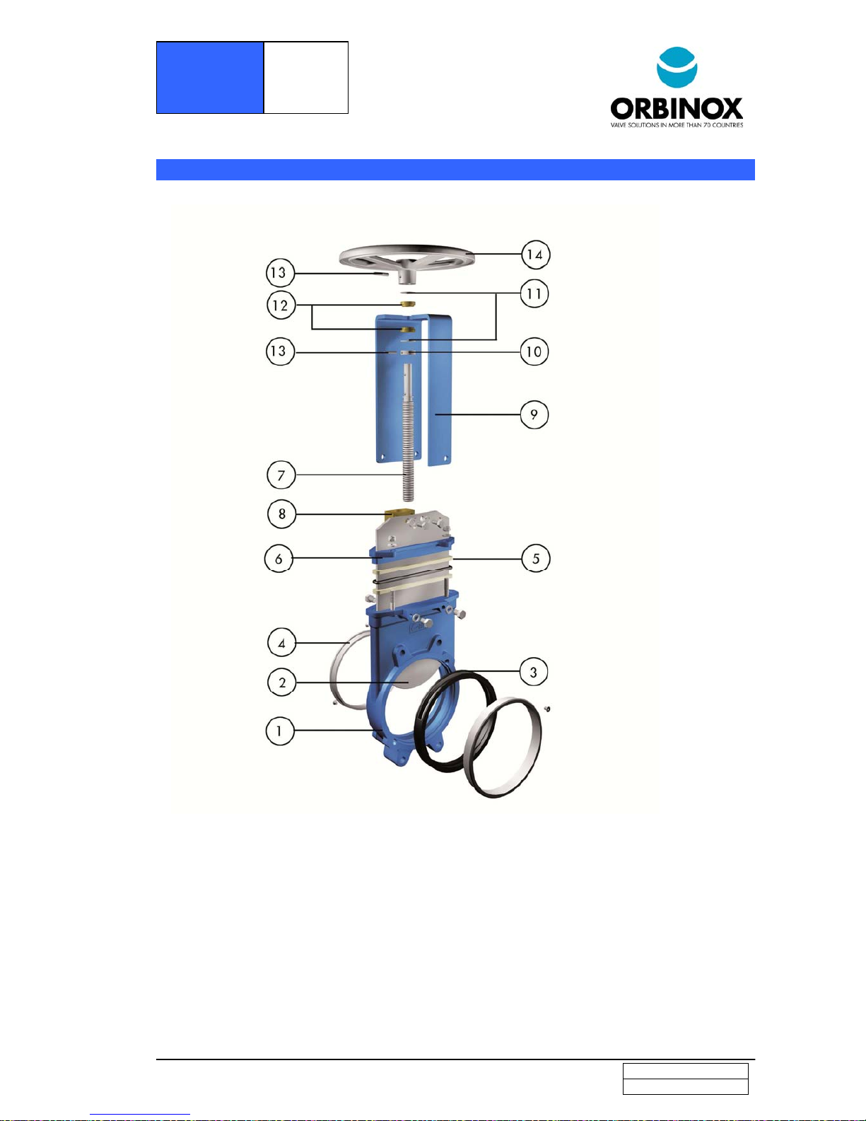
6.- PARTS LIST & DRAWINGS
1.- BODY 8.- STEM NUT
2.- GATE 9.- YOKE
3.- SLEEVE 10.- AXIAL FIXING BUSH
4.- SEAT RING 11.- FRICTION WASHER
5.- PACKING 12.- GUIDE BUSH
6.- GLAND FOLLOWER 13.- SPRING PIN
7.- STEM 14.- HANDWHEEL
 Loading...