

Page 1
INSTALLATION, OPERATION AND
MAINTENANCE MANUAL
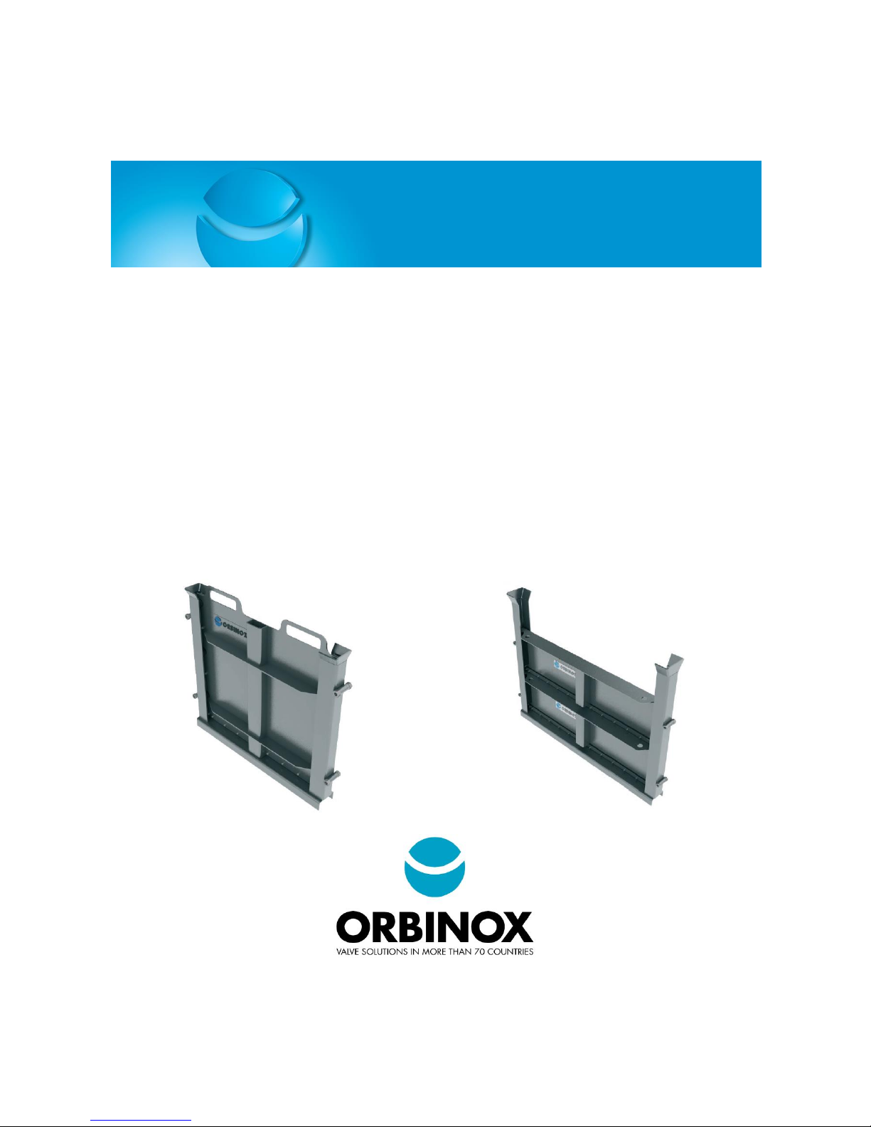
AG STOP GATE
SL STOP LOG
Page 2

IOM MANUAL
AG STOP GATE
SL STOP LOGS
www.orbinox.com
EDITION 01/2017
IOM-AG-SL
1. INTRODUCTION ................................................................................................................................................................................ 2
2. EQUIPMENT MAIN COMPONENTS ................................................................................................................................................... 3
3. HANDLING AND STORAGE ................................................................................................................................................................ 4
4. INSTALLATION .................................................................................................................................................................................. 5
4.1. EMBEDDED IN CONCRETE (IN THE CHANNEL RECESS) ................................................................................................................ 5
4.2. FACE MOUNTED (IN EXISTING CHANNEL WITHOUT RECCESSES) ................................................................................................ 6
4.3. WALL MOUNTED (AT THE END OF THE CHANNEL) ...................................................................................................................... 8
5. START-UP AND COMMISSIONING .................................................................................................................................................... 9
6. OPERATION .................................................................................................................................................................................... 10
7. MAINTENANCE ............................................................................................................................................................................... 11
7.1. CLEANING AND LUBRICATION ................................................................................................................................................... 11
7.2. SEAL REPLACEMENT: SEAL ATTACHED TO THE SLIDE ................................................................................................................ 12
8. TROUBLESHOOTING ....................................................................................................................................................................... 13
9. ANNEX: CIVIL WORK TOLERANCES ................................................................................................................................................. 14
1. INTRODUCTION
This manual describes the recommended procedures for installation, operation, maintenance and safety
precautions for the following Orbinox equipment:
o AG stop gates
o SL stop logs
The manual uses AWWA C561 terminology (see section 2). “Slide gate” or “gate” are also general terms used to
refer to all type of equipment.
Sections of the manual that do not specifically state the equipment type are applicable to all equipment types.
Please read thoroughly all the instructions in the manual prior to installation, and contact an Orbinox
representative in case of any questions.
The manual makes reference to the “General Arrangement Drawing” (GAD). The GAD is the drawing that is sent
to and approved by the customer prior to the production of the slide gate. The manual shall be used in conjunction
with the GAD.
Orbinox assumes no responsibility or liability if the slide gate is not installed, operated and maintained in strict
accordance to the procedures described in this manual.
Page 3
IOM MANUAL
AG STOP GATE
SL STOP LOGS
www.orbinox.com
EDITION 01/2017
IOM-AG-SL
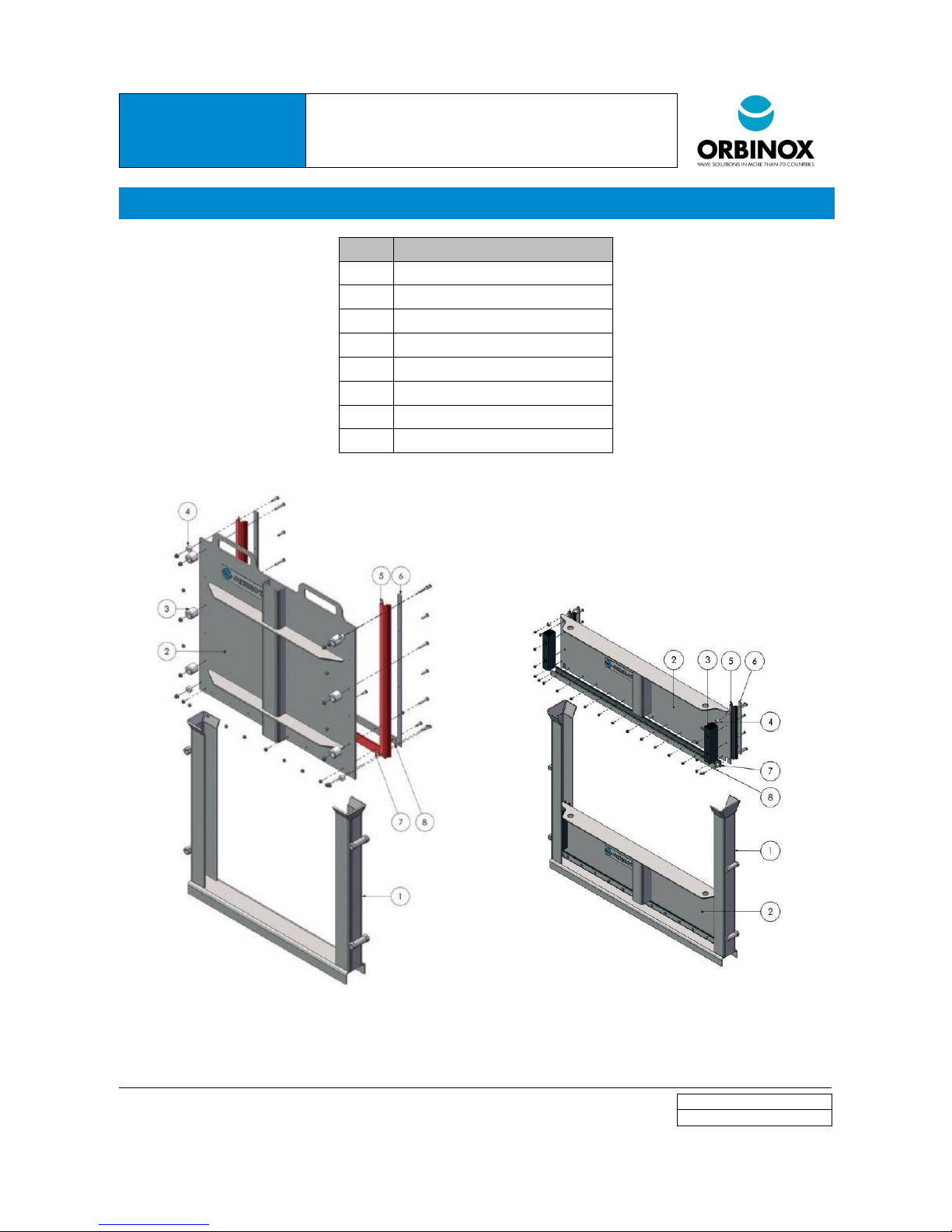
2. EQUIPMENT MAIN COMPONENTS
ITEM
DESCRIPTION
1
FRAME
2
SLIDE (FOR AG), LOG (FOR SL)
3
GUIDE
4
LATERAL GUIDE
5
VERTICAL SEAL
6
VERTICAL SEAL RETAINER
7
BOTTOM SEAL
8
BOTTOM SEAL RETAINER
Figure 1: AG Stop Gate
Figure 2: SL Stop Log
(GATE DIVIDED IN TWO OR MORE LOGS)
Page 4

IOM MANUAL
AG STOP GATE
SL STOP LOGS
www.orbinox.com
EDITION 01/2017
IOM-AG-SL
3. HANDLING AND STORAGE
Handling
Standard safety procedures shall be followed to prevent personal injury or equipment damage.
The equipment shall be lifted from the main frame. For bigger gates, the frame comes with hoist rings specially
arranged for handling purposes.
Never lift the gates in the inverted position or from the slide.
Storage
Check the equipment on delivery and report back to Orbinox any missing components within 3 days from receipt
of the equipment. Orbinox will not accept responsibility for loss or damage to any equipment which has occurred
after this period.
Some gates might be packed with wooden strips (or steel beams) between both frame guides. Do not remove the
strips/beams before the gate has been properly installed in order to avoid any damage or distortion to the frame.
Equipment shall be stored in a dry, clean and even area on a raised even wood surface to prevent distortion of
the frame. Do not stack slide gates.
Page 5
IOM MANUAL
AG STOP GATE
SL STOP LOGS
www.orbinox.com
EDITION 01/2017
IOM-AG-SL
4. INSTALLATION
This section describes the different installation methods (See section 4.1 to 4.3). Please refer to the GAD to identify
the installation method that is applicable to the purchased equipment.
The concrete construction shall be flat, level and plumb, and shall be in accordance to DIN 18202 or equivalent
ACI 117-06 standard (see Section 9). If necessary, use non-shrink grout in order to meet the specified standard.
The minimum concrete strength shall be 25 MPa (3,600 PSI).
The following procedures are general installation guidelines. Please refer to the notes on the GAD for specific
information about the installation method and the required materials (type, size and quantity of anchor bolts,
construction sealant, etc.). Always follow the anchor bolt and construction sealant manufacturers’ installation
instructions. Note that, typically, construction sealant requires dry concrete surfaces for its application.
Note that as standard, installation materials such as anchor bolts, hex-bolts and construction sealant are not
supplied with the equipment, unless otherwise specified.
4.1. EMBEDDED IN CONCRETE (IN THE CHANNEL RECESS)
Step 1: Initial assessment
Check that the concrete wall meets the requirements described in Section 4.
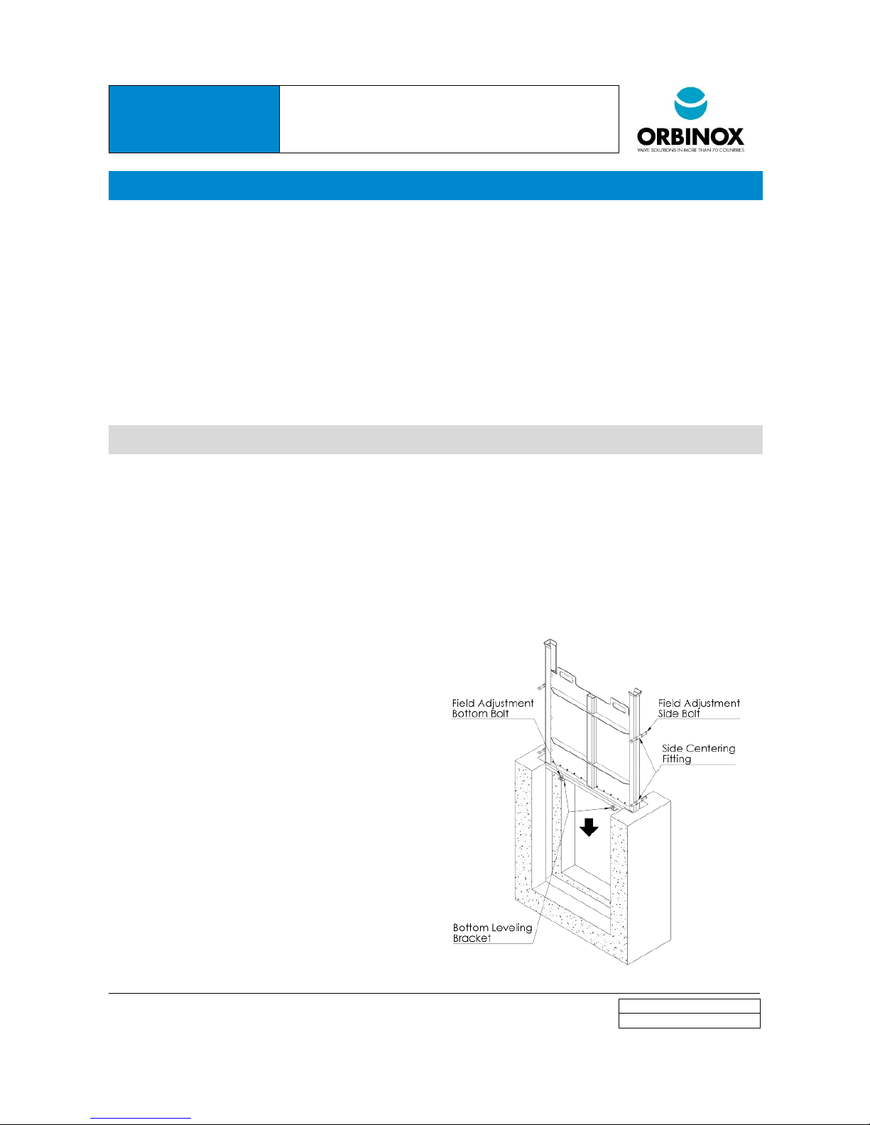
Verify that all installation materials specified on the GAD are available. Wooden wedges are used to center and
level the gate in the recess prior to embedding it in concrete. Optionally, the unit includes Side Centering Fittings
and Bottom Leveling Brackets which ease the positioning of the unit. In this case, hex-bolts are used.
Step 2: Frame alignment in the recess
Position and center the unit in the recess of the wall,
using wooden wedges (or field adjustment bolts if the
gate includes Side Centering Fittings and Bottom
Leveling Brackets).
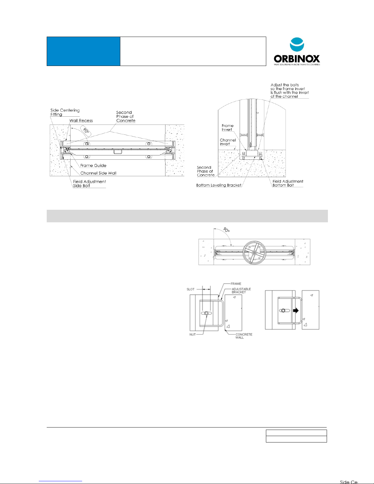
Align the unit vertically and make sure that the
frame is flush with the invert of the channel. Adjust the
bolts on the "Bottom Leveling Brackets" if applicable
(See Figure 5).
Align the unit horizontally and make sure that the
Frame Guide is flush with the channel side wall.
Additionally, make sure that the gate is perpendicular
to the side walls of the channel. Adjust the bolts on the
“Lateral Centering Fittings” if applicable (see Figure
4).
Step 3: Frame embedment in the wall recess
Pour the second phase of concrete. Take special
care not to damage the seals.
Do not pour in more than one meter concrete
columns to avoid damage to the frame.
Figure 3
Page 6
IOM MANUAL
AG STOP GATE
SL STOP LOGS
www.orbinox.com
EDITION 01/2017
IOM-AG-SL
Figure 4
Figure 5
4.2. FACE MOUNTED (IN EXISTING CHANNEL WITHOUT RECCESSES)
Step 1: Initial assessment
Check that the concrete wall meets the requirements
described in Section 4.
Verify that all installation materials specified on the
GAD are available. Anchor bolts and grout are used
for this type of installation.
Step 2: Anchor the gate to the side of the channel
Position the unit in the existing channel. Make sure
that the gate is perfectly aligned and centered in the
channel (see Figure 6).
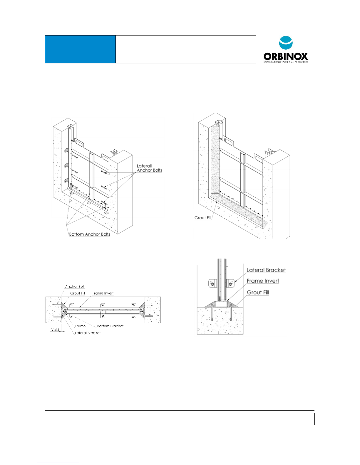
Install the bottom anchor bolts, and then the lateral
anchor bolts (see Figure 8). All Face Mounted Channel
Gates include lateral mounting
Figure 6
Figure 7
brackets. For smaller sizes (typically under 1500mm/ 60”), the channel gate includes lateral flexible brackets (as
seen in Figure 7) that require no field adjustment. For bigger sizes (typically above 1500mm/60”), the channel
gate includes “Field Adjustment Brackets”. In order to adjust the bracket, the following steps shall be followed (see
Figure 7):
o Adjust the bracket until it is completely leaning against the wall
o Secure the bracket with the nut and install the anchor bolt
Step 3: Grout fill
Grout-fill the remaining voids (See Figure 9), both at the bottom (See Figure 11) and laterals of the gate. Remember
Page 7
IOM MANUAL
AG STOP GATE
SL STOP LOGS
www.orbinox.com
EDITION 01/2017
IOM-AG-SL
that the objective of the grout fill is twofold:
o Fill the voids between the frame, frame invert and the channel.
o Make a smooth transition for water flow.
CAUTION! Make sure not to get grout or any other foreign material on the gate’s seals, guides or stem as this may
cause leakage or damage.
Figure 8 Figure 9
Figure 10 Figure 11
Page 8
IOM MANUAL
AG STOP GATE
SL STOP LOGS
www.orbinox.com
EDITION 01/2017
IOM-AG-SL
4.3. WALL MOUNTED (AT THE END OF THE CHANNEL)
Step 1: Concrete construction inspection
Check that the concrete wall meets the requirements
described in Section 4.
Verify that all installation material specified on the GAD is
available. The equipment is installed by means of anchor
bolts. Construction sealant shall be used between the frame
and the concrete wall. Alternatively, sponge EPDM rubber can
be used.
Step 2: Equipment pre-installation
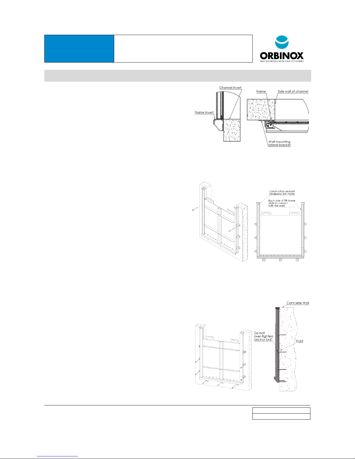
Present the unit to its required position and ensure that the
invert of the frame is flush with the civils. Also make sure that
the equipment is centered with respect to the channel opening
(See Figure 12).
Drill and install one anchor bolt on each side of the frame
(See Figure 13). After installing the first anchor bolt, and prior
to drilling the hole on the other side, make sure the frame is
perfectly leveled.
Step 3: Construction sealant application
Remove the unit from the wall (first remove the nuts of the
anchor bolts).
Apply construction sealant all around the perimeter of the
frame. Be sure not to get sealant on the gate’s seals and/or
guides, as this may cause leakage or damage. (See Figure
14).
Re-install the slide gate on the wall and tighten both anchor
bolts.
Step 4: Final installation
Drill and install the rest of the anchor bolts (see Figure 15).
CAUTION! If the unit is not completely in contact with the
wall, do not over-tighten the anchor bolts. Over tightening
may bend or distort the frame. If the wall flatness and
levelness is according to the specified standards, the
construction sealant will fill in the remaining voids (see Figure
16).
Apply construction sealant around the frame perimeter in
order to fill in any existing gap between the wall and the
frame (200ml/meter) Wipe away the excess sealant to leave a
smooth finish.
Figure 12
Figure 13
Figure 14
Figure 15
Figure 16
Page 9

IOM MANUAL
AG STOP GATE
SL STOP LOGS
www.orbinox.com
EDITION 01/2017
IOM-AG-SL
5. START-UP AND COMMISSIONING
Do not operate the gate unless it is completely necessary. Typically the plant (i.e.: waste water treatment plant) has
not been finished when the commissioning occurs. Therefore, dust and dirt tends to accumulate on the seals and
stems. Do not apply extra grease on the seal and/or stem until the construction of the plant has been completely
finished as it forms a sticky paste with the dust. If the equipment needs to be operated previously wet the seals.
Clean the unit with clear water and make sure there are no foreign deposits or materials on the seals, guides or
sealing area. Use plastic tools to remove any foreign material in order not to contaminate the stainless steel
equipment.
Visual Inspection
Verify that all installation instructions defined in the GAD and the IOM manual have been followed.
Verify that the seal is in compression against the frame (or logs in case of SA aluminum stop logs). Use a 0.5mm
(1/32”) gauge.
Embedded In concrete installation:
o Check that the frame (or other embedded parts) has not been distorted during installation. Measure the
opening width every 1 meter. The maximum deviation should be +-width/1000.
o Verify that the frame invert has been embedded in concrete.
Wall mounted at the end of the channel installation. Verify that there are no voids between the concrete wall and
the back of the frame (open the gate and look on the sides). No light must go through the frame and the wall. Clean
water can also be used to verify water tightness between the concrete wall and frame.
Face mounted in existing channel installation:
o Check that the frame has not been distorted during installation. Measure the opening width every 1 meter.
The maximum deviation should be +-width/1000.
o Check that the frame has been grouted as indicated in the GAD
Field Operational Test:
Before cycling the unit, make sure there are no foreign deposits or materials on the seals, guides or sealing area.
Clean the unit with clear water. Gate seals could be damaged if the area is not cleaned and coated with grease.
Please refer to Section 7.1 for detailed information.
Seals shall be wetted with clear water before operating the slide gate, and stems and stem nuts shall be greased.
Field Leakage Test
Close the slide and pressurize the unit at the design water head.
Collect the leaked water during a period of time of 10 minutes (L
T10
)
Calculate the leakage rate: LR (L/min and m) = L
T10
/(10*P), where P is the sealing perimeter in meters.
Page 10

IOM MANUAL
AG STOP GATE
SL STOP LOGS
www.orbinox.com
EDITION 01/2017
IOM-AG-SL
6. OPERATION
Seals shall be wet while operating. If the slide gate has not been used for a long period of time under dry
conditions, the seals shall be wetted with clear water before operating the slide gate. Operating the gate with dry
seals may damage them, and additional thrust might be required to operate the slide. Please refer to section 7.1 for
detailed information about the required grease type.
The following equipment can be used to lift up the gate or logs:
o Hand-pull: the slide or logs are equipped with handles. ORBINOX recommends the use of other methods
for pull out forces higher tan 50kg [110 pounds], or 25kg per person [55 pounds]. Refer to the GAD for
pull out force detailed information. Hand poles can be supplied for remote operation.
o External crane: the slide or logs are equipped with bull eyes to be lifted with an external crane.
Optionally, a lifting device (beam) can be supplied.
Page 11
IOM MANUAL
AG STOP GATE
SL STOP LOGS
www.orbinox.com
EDITION 01/2017
IOM-AG-SL
7. MAINTENANCE
7.1. CLEANING AND LUBRICATION
Orbinox equipment is designed to give trouble free operation with minimum maintenance work. However, it is very
important to follow the next simple maintenance activities at the defined frequency to ensure an optimum
performance of the equipment.
Every six months or 100 cycles (whatever occurs first):
Visually inspect the unit for signs of misalignment, damage or corrosion. Also, verify that all parts are in place.
Clean the unit with clear water and remove any deposits, especially on the seals and guides.
Lightly grease all moving parts.
Check the seals and make sure they are not damaged. Seals shall be replaced if damaged (see section 7.2).
Check tightness of all unit assembly bolts and anchor bolts.
Spare parts: Orbinox does not recommend stocking any spare parts by the owner of the equipment. If a repair part
is required, please contact an Orbinox representative and provide the following information:
Orbinox sales order number.
GAD number.
Project name (if applicable) and vendor’s company name.
Materials needed for maintenance and seal replacement:
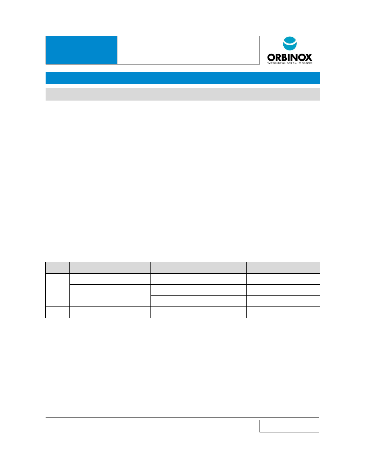
Material
Application
Type
Recommended
Grease
Seal and guides
Silica-Gel Silicone Grease
Vercol-Verkosil G-2
General purpose (seals, guides, threads) -
Drinking water applications
ACS and NSF61 approved Silicone Grease
Dow Corning-Molykote 111
WRAS approved Silicone-Grease
Rocol-Sapphire Aqua-sil High Load
Adhesive
Seal joints
Instant Adhesive
Loctite 406 or 495
Page 12
IOM MANUAL
AG STOP GATE
SL STOP LOGS
www.orbinox.com
EDITION 01/2017
IOM-AG-SL
7.2. SEAL REPLACEMENT: SEAL ATTACHED TO THE SLIDE
Step 1: Remove the slide
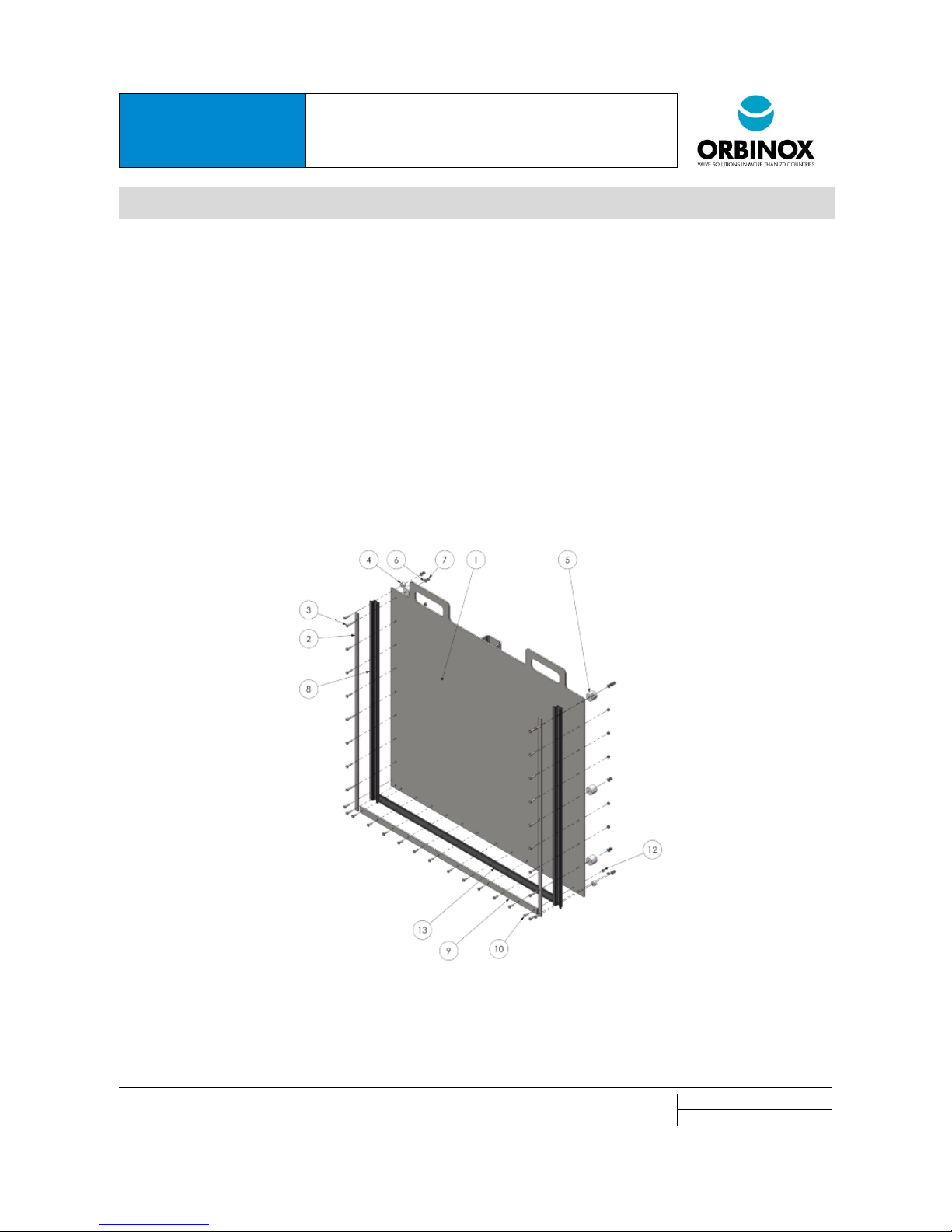
Step 2: Side seals replacement (Figure 17)
o Remove bolts, washers and nuts (items 3, 6 and 7) from the gate and remove retainers (items 2), lateral
and front polyethylene guides (items 4 and 5).
o Remove side seals (item 8) and replace it by the new seal.
o Note 1: Apply glue where the bottom seal and side seals join.
o Note 2: After installing the new seal, apply grease on it.
Step 3: Bottom seal replacement (Figure 17)
o Remove bolts and nuts (items 10 and 12) and remove bottom retainer (item 9).
o Remove bottom seal (item 13) and replace it by the new seal.
o Note 1: Apply glue where the bottom seal and side seals join.
Reassembly: Follow Steps 3 to 1.
Figure 17
Page 13
IOM MANUAL
AG STOP GATE
SL STOP LOGS
www.orbinox.com
EDITION 01/2017
IOM-AG-SL
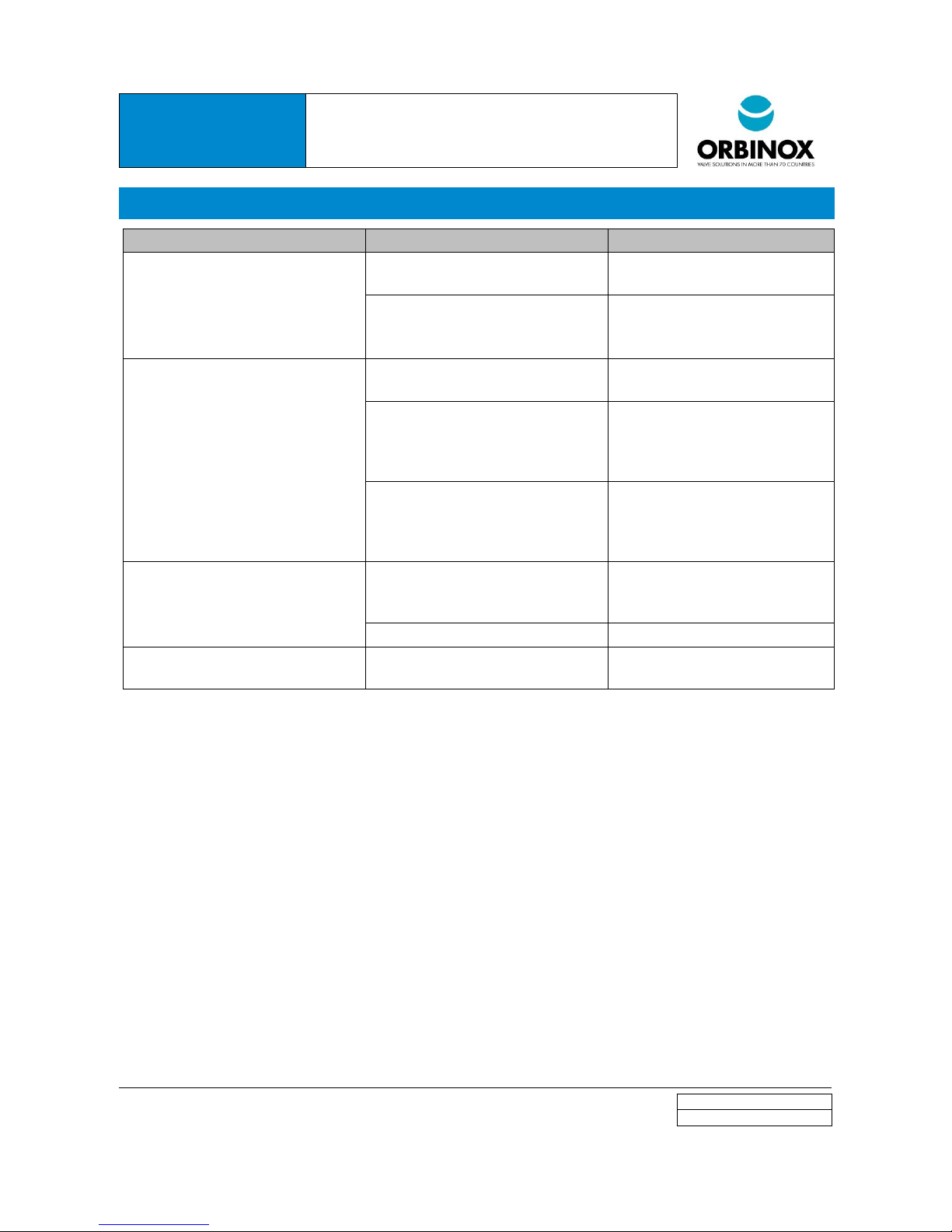
8. TROUBLESHOOTING
SYMPTOM
CAUSE
SOLUTION
LEAKAGE (Between frme and
concrete wall, for Face Mounted In
Existing Channel Configuration)
Concrete Wall does not meet the
required tolerance specification
Uninstall unit, repair the concrete
wall and re-install the unit
Gaps between frame and face of
wall due to miss-application of
grout fill
Grout Fill remaining gaps
LEAKAGE (Leakage between frame
and concrete wall, for Wall Mounted
Configuration).
Concrete Wall does not meet the
required tolerance specification
Uninstall unit, repair the concrete
wall and re-install the unit
Insufficient construction sealant
(refer to the GAD)
Uninstall the unit, clean the
concrete wall, and apply new
construction sealant (refer to the
GAD for type and quantity).
Loose anchor bolts
Incorrect anchor bolts (refer to the
GAD)
Tighten anchor bolts
Install appropriate anchor bolts
(refer to the GAD for type and
quantity)
LEAKAGE (through the bottom seal)
Foreign deposits trapped in
between the frame invert and bottom
seal
Open slightly the slide and
remove all foreign deposits. Check
if bottom seal has been damaged.
Damaged bottom seal
Replace bottom seal
EXCESSIVE FORZE REQUIRED FOR
OPERATION
Dry seals
Wet seals
Page 14
IOM MANUAL
AG STOP GATE
SL STOP LOGS
www.orbinox.com
EDITION 01/2017
IOM-AG-SL
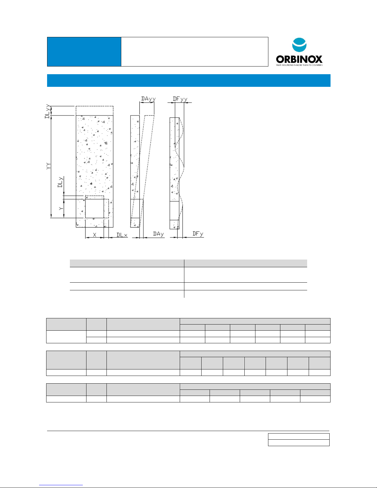
9. ANNEX: CIVIL WORK TOLERANCES
X: opening width
Y: opening height
YY: invert to coping distance
DLx: linear deviation (with respect to X dimension)
DLy: linear deviation (with respect to Y dimension)
DLyy: linear deviation (with respect to YY dimension)
DAy: angular deviation (with respect to Y dimension)
DAx: angular deviation (with respect to X dimension)
DAyy: angular deviation (with respect to YY
dimension)
DFy: flatness deviation (with respect to Y dimension)
DFx: flatness deviation (with respect to X dimension)
DFyy: flatness deviation (with respect to YY
dimension)
Deviations shall be within the tolerances defined in DIN 18202:
Deviation
Maximun deviation
Linear deviation (DLx, DLy, DLyy):
DIN 18202, table 1, group 2 (for DLx e DLy)
DIN 18202, table 1, group 5 (for DLyy)
Angular deviation (DAx, DAy, DAyy)
DIN 18202, table 2
Flatness deviation (DFx, DFy, DFyy)
DIN 18202, table 3, group 7
The following tables show the tolerances defined in DIN18202:
DIN 18202
TABLE 1
Group
Applicable to
Max. admissible deviation (mm) for target size (m)
<=1
>1 <=3
>3 <=6
>6 <=15
>15-<=30
>30
Linear deviation
Group 2
DLx, DLy
+-10
+-12
+-16 - -
-
Group 5
DLyy
+-10
+-16
+-16
+-20
+-30
+-30
DIN 18202
TABLE 2
Group
Applicable to
Max. admissible deviation (mm) for target size (m)
<=0,5
>0,5 <=1
>=1 <3
>=3 <6
>=6 <15
>=15-
<30
>=30
Angular deviation
DAx, DAy, DAyy
3 6 8
12
16
20
30
DIN 18202
TABLE 3
Group
Applicable to
Max. admissible deviation (mm) for target size (m)
<0,1
>=0,1 <1
>=1 <4
>=4 <10
>=4 <10
Flatness deviation
Group 7
DFx, DFy, DFyy
2 3 8
15
20
 Loading...